MC260 - Grasmaaier Maruyama - Gratis gebruiksaanwijzing en handleiding
Vind de handleiding van het apparaat gratis MC260 Maruyama in PDF-formaat.


| Type product | Grasmaaier (multicutter) met verwisselbare gereedschappen |
| Merk | Maruyama |
| Model | MC260 (MC260S/MC260C/MC260E/MC260D) |
| Gewicht (zonder brandstof) | 11,9 – 15,9 lbs (5,4 – 7,2 kg) afhankelijk van uitvoering |
| Motorinhoud | 25,4 cc |
| Brandstoftankinhoud | 0,85 liter (0,85 Qt) |
| Brandstofmengsel | 50:1 met Maruyama 2-takt olie; 25:1 met andere 2-takt olie |
| Ontsteking | Solid-state (elektronisch) |
| Bougie | NGK BPM6Y, elektrodenafstand 0,024-0,028 inch (0,6-0,7 mm) |
| Carburateur | Walbro membraantype (WYK) |
| Handgreep | Lusgreep (loop handle) |
| Toepassingen | Gras trimmen, onkruid snoeien, haagscheren (MC260D), randsnijden (MC260E) |
| Veiligheidsvoorzieningen | Beschermkap, stopknop, vonkenvanger, geluiddemper |
| Onderhoud | Luchtfilter reinigen, bougie vervangen, versnellingsbak smeren, flexibele as smeren |
| Schouderriem | Inbegrepen (voor metaalblad verplicht) |
| Garantie | 2 jaar particulier gebruik, 6 maanden commercieel gebruik |
| Gereedschapsset | Inbegrepen (inbussleutel, etc.) |
Veelgestelde vragen - MC260 Maruyama
Gebruikersvragen over MC260 Maruyama
0 vraag over dit apparaat. Beantwoord die u kent of stel uw eigen vraag.
Stel een nieuwe vraag over dit apparaat
Download de handleiding voor uw Grasmaaier in PDF-formaat gratis! Vind uw handleiding MC260 - Maruyama en neem uw elektronisch apparaat weer in handen. Op deze pagina staan alle documenten die nodig zijn voor het gebruik van uw apparaat. MC260 van het merk Maruyama.
GEBRUIKSAANWIJZING MC260 Maruyama
INSTRUCTION MANUAL
FOR MULTI-CUTTER: POWER UNIT WITH TOOL ATTACHMENTS MODELS: MC260/MC260S/MC260C/MC260E/MC260D

It is essential that any operator of a MARUYAMA Multi-Cutter reads and understands the contents of this manual before the engine is started.
Important safety instructions will be identified by the safety symbol.

Failure to comply with the instructions in this manual may result in serious injury.
FOREWORD
This Instruction Manual is designed to familiarize the operator with the various features and component parts of the equipment and to assist you with the assembly, operation and maintenance of your new Multi-Cutter and Tool Attachments.
Special attention should be given to the Safety Instructions provided throughout the Instruction Manual.
Please read this Instruction Manual carefully before using the Multi-Cutter and Tool Attachments, and acquaint yourself thoroughly with the equipment.
For additional assistance, contact any local authorized MARUYAMA dealer, or MARUYAMA U.S., Inc., 301-30 th St. NE, Suite 118, Auburn, WA 98002.
TABLE OF CONTENTS
Page
Page
Foreword 1
Specifications 1
Safety Instructions 2
Model Identification....3
Assembly Instructions ....4
* Engine and driveshaft (Power Unit)……4
* Loop Handle 4
* Throttle cable and wiring ……4
* Straight shaft tool ....5
* Curved shaft tool 6
* Hedge Trimmer tool 6
* Edger tool 6
* Connecting the tool attachments to the power unit…7
Before Operation 8
* Fuel: Mixing gasoline and oil……8
* Fuel-mixture chart ....8
Operating Instructions 9
* Starting procedure ......9
* Engine operation....10
* Stopping the engine …… 10
* Carburetor adjustment …… 10
Operating the Multi-Cutter and Tool Attachments ……11
* Cutting with nylon trimmer line……11
* Using metal cutting-blades · 12
* Hedge Trimmer operation……13
* Edger operation....14
Regular Maintenance 15
* Air filter 15
* Spark plug 15
* Cooling fins....15
* Fuel filter 16
* Spark arrestor 16
* Exhaust muffler....16
* Lubrication: Gearcase....17 Flexible driveshaft....17
* Adjusting the cutting blades · 18
* General cleaning and tightening …… 18
Storage 18
Warranty 19
SPECIFICATIONS
| MC260+MC260S | MC260+MC260C | MC260+MC260D | MC260+MC260E | |
| DRY WEIGHT | 12.3 lbs | 11.9 lbs | 15.9 lbs | 13.4 lbs |
| HANDLE CONFIGURATION | LOOP HANDLE | |||
| ENGINE DISPLACEMENT | 25.4cc | |||
| FUEL TANK CAPACITY | 0.85Qts | |||
| CARBURETOR | WALBRO DIAPHRAGM TYPE WYK | |||
| IGNITION | SOLID STATE SYSTEM | |||
| SPARK PLUG | NGK BPM6Y SET GAP 0.024-0.028 INCHES | |||
| FUEL MIXTURE | USE ONLY NON-LEADED REGULAR GASOLINE.MARUYAMA 2-CYCLE OIL MIX 50:1 RATIO* OTHER 2-CYCLE OIL MIX 25:1 RATIO* MUST BE APPROVED FOR AIR-COOLED ENGINES | |||

SAFETY INSTRUCTIONS

- Read and understand this Instruction Manual before using the equipment. Be thoroughly familiar with the proper use of the multi-cutter and the tool attachments.
- Never allow children to operate the multi-cutter. It is not a toy. Never allow adults to operate the unit without first reading the Instruction Manual.
3.Become familiar with the controls and know how to stop the engine quickly.
4.ALWAYS WEAR SAFETY GLASSES or other suitable eye protection and hearing protection. - Keep the area of operation clear of all persons, particularly small children and pets.
- Never operate a multi-cutter when you are fatigued.
- Never operate a multi-cutter without proper guards or other protective safety devices in place.
- Dress properly; do not wear loose clothing or jewelry. They can be caught in moving parts. Always wear substantial footwear, long pants, and long sleeved shirt.
- Gasoline is highly flammable; handle it carefully. Fill the fuel tank with the correct mixture of gasoline and oil before trying to start the engine.
A. Use an approved fuel container for storing the gasoline/oil mixture.
B.Do not fill the tank when the engine is hot or running.
C.Do not smoke while handling gasoline.
D. Fill the fuel tank outdoors and up to about one-half inch from the top of the tank, not the top of the filler neck.
E.Wipe any spilled gasoline before starting the engine.
-
Always be sure of your footing; keep a firm hold of the handles with both hands, and walk, never run.
-
Use the right tool for the job. Do not use the multi-cutter and tool attachments for any job that is not recommended by the manufacturer.
-
Keep all fasteners tight to be sure the multi-cutter is in safe working condition. Follow the maintenance instructions provided on page 15 to 18 of this manual.
-
Do not put hands or feet near or under any moving parts. Keep clear at all times.
-
If the multi-cutter should start to vibrate abnormally, stop the engine and check immediately for the cause. Vibration is generally a warning of trouble.
-
Do not trim too close to the ground in order to avoid hitting small stones or other debris. Avoid using the multi-cutter near rocks, gravel, stones and similar matter.
-
Use the multi-cutter only in daylight or good artificial light.
17.Shut off the engine and be certain the cutter head has completely stopped rotating before inverting the machine.
MODEL IDENTIFICATION
MC260 (MULTI-CUTTER POWER UNIT)
ENGINE:

MC260S (STRAIGHT SHAFT TOOL ATTACHMENT)

MC260C(CURVED SHAFT TOOL ATTACHMENT)

- SPARK PLUG
- STARTER HANDLE
- AIR FILTER
- FUEL TANK
- THROTTLE CABLE/STOP SWITCH WIRES
- CLUTCH-DRUM HOUSING
- SHAFT GRIP
- THROTTLE TRIGGER/ STOP-SWITCH
-
ATTACH RING FOR HARNESS
-
SHOULDER HANGING STRAP
-
LOOP HANDLE
-
SHAFT ASSEMBLY
-
SHAFT CONNECTOR
14.CLAMPING-KNOB
-
SHAFT ASSEMBLY
-
GEAR CASE
-
GUARD
-
TRIMMER HEAD
-
SHAFT ASSEMBLY
-
BEARING CASE
-
GUARD
-
LINE CUT-OFF BLADE
-
TRIMMER HEAD
MC260E (EDGER TOOL ATTACHMENT)

-
SHAFT ASSEMBLY
-
CLAMPING-KNOB
-
GUARD
-
CLAMPING BRACKET
-
DEPTH GUIDE WHEEL
-
BLADE
MC260D (HEDGE TRIMMER ATTACHMENT)

-
SHAFT ASSEMBLY
-
GEAR CASE
-
BLADES & GUIDE BAR
-
ANGLE DRIVE
-
GREASE FITTING
The MARUYAMA Multi-Cutter includes a Tool Kit, Shoulder Hanging Strap, Instruction Manual, and a Warranty Registration Card.
ASSEMBLY INSTRUCTIONS
ENGINE AND DRIVESHAFT ASSEMBLY (POWER UNIT)
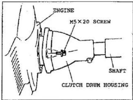
The shaft and clutch drum housing assembly are already connected. Attach the shaft to the engine with the four M5×20 screws (packed with the shaft assembly).

LOOP HANDLE
The loop handle attaches to the shaft with four screws, as shown.
THROTTLE CABLE AND WIRING
Install the plastic tube (packed with the shaft assembly) around the throttle cable and stop-switch wires, as shown.


Remove the air filter cover to connect the stop-switch wires, as shown. (Connections are near the carburetor on the engine.)
The throttle cable end must be inserted into and through the brass-colored fitting held by the bracket on top of the carburetor. The wire-end lug fits into the slotted holder (as shown) on top of the carburetor. A HOLE IS PROVIDED FOR THE LUG AT ONE END OF THE WIRE SLOT.

STRAIGHT SHAFT TOOL ATTACHMENT (MC260S)
Only the installation of the blade guard is required.
The blade guard installs onto the shaft with two screws, as shown.
NOTE: Use 3mm allen wrench (from tool kit) as a holding tool to lock the attaching shaft while installing cutting devices (see sketches).


Install the Maru-Matic trimmer head, as shown. Be sure the trimmer head is for LEFT-HAND rotation (as viewed from the operator's position) and the trimmer head adapter matches the internally-threaded splined attaching shaft of the tool (M8×1.25 LEFT-HAND).
IMPORTANT—The boss adapter and the washer(see sketch) must be installed on the splined shaft between the gearcase and the trimmer head assembly.
METAL CUTTING-BLADES (OPTIONAL):
A variety of metal cutting-blades are available to satisfy different cutting conditions. It is especially important to use only the correct blade(s) approved for the MC260S Multi-Cutter. Also, it is especially important to install the blade for LEFT-HAND rotation (as viewed from the operator's position), and to correctly position all blade-holding parts (see sketch).

| OPTIONAL CUTTING BLADE MC260S(9inch) |  P/N 210179 P/N 210179 |  P/N 210183 P/N 210183 |  P/N 913142 P/N 913142 |
CURVED SHAFT TOOL ATTACHMENT (MC260C)
Only the assembly and installation of the string guard is required. Refer to the sketch and attach the string-cutter blade to the guard with two screws, nuts, and washers. Remove the clamping screw from the guard. Push the guard onto the bearing-head housing. Replace the clamping screw and tighten ONLY AS NEEDED.


NOTE: Use 3mm allen wrench (from tool kit) as a holding tool to lock the attaching shaft while installing cutting devices (see sketches).
Install the Maru-Matic trimmer head, as shown. Be sure the trimmer head is for RIGHT-HAND rotation (as viewed from the operator's position) and the trimmer head adapter matches the threaded attaching shaft of the tool (M8×1.25 RIGHT-HAND).
HEDGE TRIMMER TOOL ATTACHMENT (MC260D)

CAUTION-THE HEDGE TRIMMER CUTTING BLADES ARE EXTREMELY SHARP AND DANGEROUS AT ALL TIMES!!
No additional assembly of the Hedge Trimmer Tool attachment is required.
EDGER TOOL ATTACHMENT (MC260E)
To install the blade guard assembly, first place the shield onto the gearcase (see sketch). Place the clamp onto the gearcase opposite the shield. Install the screw and clamping-knob, as shown, and tighten ONLY AS NEEDED.


Before installing the cutter-blade, rotate the blade-guard (on the gearcase) until the hole in the gearcase can be viewed. Next, rotate the boss adapter to align the holes for inserting the holding tool. With the holding tool inserted, place the cutting blade onto the boss adapter, and then the clamping washer onto the splined shaft. Finally, the blade bolt must be installed.
The bolt is threaded LEFT-HAND, and must be tightened quite securely (100 In.Lbs.).
CONNECTING THE TOOL ATTACHMENTS TO THE POWER UNIT
First, loosen the clamping-knob so the shaft of the tool attachment can be inserted into the tube coupler. Pull the detent knob outward and gently rotate the attachment shaft back and forth while inserting to be sure the driveshafts and guide-slot are aligned and completely in place. The spring-loaded detent knob will snap into place when the attachment shaft is correctly positioned. Tighten the clamping-knob.

BEFORE OPERATION
FUEL: MIXING GASOLINE AND OIL

CAUTION-READ SAFETY INSTRUCTIONS CONCERNING GASOLINE ON PAGE(2).
The two-cycle engine used in the MARUYAMA multi-cutter requires a mixture of GASOLINE and OIL for lubrication of bearings and other moving parts. The correct fuel mixture ratio depends upon the type of two-cycle motor oil that is used. If MARUYAMA two-cycle oil is used, the proper fuel mixture ratio is 50:1, which is 2.5oz. of oil mixed with one gallon of gasoline. If other oil for two-cycle air cooled engines is used, the proper fuel mixture ratio is 25:1, which is 5.0 oz. of oil mixed with one gallon of gasoline.
NOTE: Gasoline and oil must be premixed in a clean gasoline container. Never mix gasoline and oil indoors or in the multi-cutter fuel tank. Always use fresh gasoline.
Add a small quantity of unleaded regular gasoline to a gasoline container. Pour the proper amount of two-cycle oil into the gasoline container. Do not use multi-viscosity oils. Install the cap on the gasoline container before shaking. Shake the gasoline container vigorously so the oil mixes with the gasoline. Add the additional gasoline needed to complete the required amount (see the fuel mixture chart below).
IMPORTANT: Do not fill the fuel tank with gasoline that does not have oil mixed in it. Do not use gasoline additives because the engine could be damaged.

WARNING!!—NEVER USE GASOHOL OR ALCOHOL BLENDED FUELS IN MARUYAMA ENGINES.
Before filling the multi-cutter fuel tank, clean around the fuel tank cap so dirt and debris does not enter the fuel tank. Always shake the fuel container before filling the fuel tank. Remove the fuel cap, then fill the fuel tank to within 1/4-1/2 inch from the top of the tank. Avoid filling the fuel tank filler neck. Install the cap securely onto the fuel tank.
FUEL MIXTURE CHART
| MARUYAMA 2-CYCLE OIL (50:1) | OTHER 2-CYCLE OIL (25:1) |
| WITH 1 GALLON GASOLINE MIX 2.5 OZ OIL | WITH 1 GALLON GASOLINE MIX 5.0 OZ OIL |
OPERATING INSTRUCTIONS
STARTING PROCEDURE
ALL MODELS: The carburetors on MARUYAMA engines do not contain a choke system and are designed to start at IDLE speed. A greater throttle setting will cause difficult starting.
To properly start a "cold" engine, perform the following procedure.
Step #1) Pump the primer-bulb at the bottom of the carburetor until fuel can be seen flowing through the fuel-return line to the fuel tank. (Flowing fuel should be clear, not foamy or full of bubbles.)

Step #2) Fully depress the black injection button, then release.

Step #3) With the ignition switch "ON", and the throttle trigger positioned at IDLE, pull the starter cord. The engine should start at IDLE within 5 to 6 pulls.

For starting an engine that is already warmed-up(hot restart), or if the ambient temperature exceeds 70°F(20°C) , the injection button should not be used. Follow steps #1) and #3) only.
If the engine fails to start at the IDLE position, set the throttle trigger at the FAST-IDLE position (see sketch). Then repeat the starting procedure (prime, injection, and pull).
(If a MARUYAMA engine fails to start after following the above procedures, contact an authorized MARUYAMA dealer.)
ENGINE OPERATION
ALL MODELS: After starting, allow the engine to a run a few minutes to warm it up before using.
NOTE: DO NOT have the engine under any load during this warm up period.
By squeezing the throttle trigger, increase the engine RPM to the speed required for operation before placing the cutting attachment under load. ALWAYS reduce the engine speed to idle when it is not under a load. Do not operate the engine at high RPM's with no load.
STOPPING THE ENGINE
ALL MODELS: Always run the engine at idle speed for a few minutes to allow cooling before stopping. To stop the engine, move the stop-switch to the STOP position.

If the stop-switch fails to stop the engine, pump the primer-bulb at the bottom of the carburetor a few times, then depress the black injection button. (Repair the stop-switch.)
CARBURETOR ADJUSTMENT
ALL MODELS: The carburetor has been carefully adjusted at the factory and should not require any further adjustment.
Only the idling speed can be adjusted by turning the idle speed adjustment screw (see sketch). The correct idle speed is 2800-3200RPM. Turning the adjustment screw clockwise will increase the idle speed.
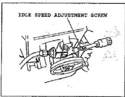
If further adjustment is necessary, please contact a local authorized MARUYAMA dealer.
OPERATING THE MULTI-CUTTER AND TOOL ATTACHMENTS

CAUTION-Read the SAFETY INSTRUCTIONS on page(2) concerning the proper use of the Multi-Cutter and Tool Attachments.
The MARUYAMA Multi-Cutter and Tool Attachments are designed and tested to cut nearly all grasses, thick weeds, and brush. As you continue to use the equipment, many tasks will become easier.
By adjusting the handles, the MARUYAMA Multi-Cutter can be operated while standing in a natural position, and can be positioned at the right or left side of the operator. (EXCEPT THE EDGER TOOL ATTACHMENT MC260E.) To adjust the loop handle, see the ASSEMBLY INSTRUCTIONS on page (4).
If it is necessary to reposition the shaft grip, loosen the clamping screw of the throttle trigger assembly before moving the grip. Then use caution to prevent any damage to the throttle cable and stop-switch connections.
Be sure the throttle trigger assembly is in place firmly against the shaft grip before tightening the clamping screw.

Adjust the blade guard to a position that does not make contact with the blade or trimming line, and shields the operator from thrown debris.
(See ASSEMBLY INSTRUCTIONS for blade guards.)

Always be sure the Tool Attachments are properly connected to the Power Unit (See ASSEMBLY INSTRUCTIONS).

Remove any holding tools before operating the equipment!
CUTTING WITH NYLON TRIMMER LINE
MODELS MC260C AND MC260S: It is only the outer tip (or end) of the trimmer line that performs the actual cutting action. The trimming operation can be a side to side or forward and backward motion. Tilting the trimmer head slightly downward when moving toward the area being cut produces a better result (see sketch).
Moving too fast or forcing the unit will cause trimmer line breakage, entanglement, or stalling the engine. Do not attempt to cut thick, stalky weeds or brush that exceeds the capability of the machine.
(Continuous overload may cause damage to the machine.) Whenever grass or debris winds onto the shaft or trimmer head, immediately stop the machine and remove the interfering material.

USING METAL CUTTING BLADES
MODEL MC260S:

CAUTION-Read the SAFETY INSTRUCTIONS concerning proper use of the multi-cutter on page (2).

CAUTION-Observe all warnings that appear on the multi-cutter and tool attachments.

CAUTION-Use only the correct blade approved for the task and the machine. See the Blade Chart and Instructions on page (5).

CAUTION—Always use the Shoulder Hanging Strap or Full Support Harness (optional) when operating a multi-cutter with a metal blade. The multi-cutter must be positioned to the right side of the operator when used with a metal blade.

CAUTION—Always make certain the blade is installed to rotate in the proper direction and that all holding and fastening parts are correctly secured.

CAUTION-Remove any holding tools before operating the equipment!

CAUTION-Do not continue to use a blade that is dull, damaged, or that vibrates during use. Whenever a cutting blade becomes clogged with debris, immediately stop the machine and clean the blade.

CAUTION-When cutting heavy brush or small trees, use the proper method to avoid dangerous "KICK-BACK" (See sketch).


HEDGE TRIMMER OPERATION
MODEL MC260D:
Refer to the ASSEMBLY INSTRUCTIONS and properly secure the Hedge Trimmer tool attachment to the power unit.

CAUTION-The cutting blades are extremely sharp and dangerous at all times. Wear protective clothing.
Before operating the Hedge Trimmer, refer to the REGULAR MAINTENANCE instructions and lubricate the cutting blades and gearcases. Be sure the cutting blades are properly adjusted.
When starting the engine, hold the Power Hedge Trimmer flat against the ground with the left hand while pulling the starter grip with the right hand (see sketch).
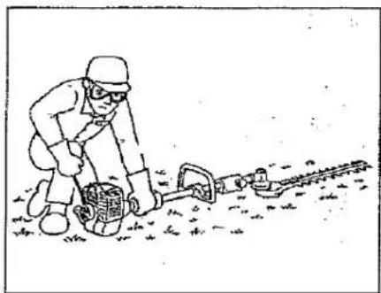
Always grip the Power Hedge Trimmer with both hands while it is in operation. Be sure the cutting blades are moving (at least half-throttle) before actual cutting begins. The Power Hedge Trimmer works best at full throttle.

The MARUYAMA Power Hedge Trimmer is designed for cutting and trimming foliage and small branches up to 1/4 inches in diameter. Although the Power Hedge Trimmer is capable of cutting larger diameter branches, wear and tear of the machine would be proportionally increased.
If the cutting blades become jammed, stop the engine immediately. Make certain all moving parts have stopped and disconnect the spark plug before inspecting the equipment for damage. Never use a Power Hedge Trimmer that has chipped, cracked, or broken cutting blades.
EDGER OPERATION
MODEL MC260E:
Refer to the ASSEMBLY INSTRUCTIONS and properly secure the edger tool attachment to the Power Unit, and securely install the cutting blade.

CAUTION-Remove any holding tools before operating the equipment!

The cutting depth should be established before starting the engine.
To adjust the cutting depth, first loosen the clamping-knob. Then rotate the blade guard forward or backward until the desired cutting depth is acquired (see sketch). Tighten the clamping-knob ONLY AS NEEDED.


Always operate the edger positioned at the RIGHT-SIDE of the operator (see sketch).
Be sure the blade is rotating (at least half-throttle) before inserting it into the cut. The multi-cutter edger performs best at full throttle.

Always use eye protection when operating the edger.

REGULAR MAINTENANCE
AIR FILTER
ALL MODELS: The air filter should be cleaned each time the multi-cutter is used. (or more often with extreme conditions.) The filter cover can be removed by unscrewing the single knob (see sketch).
Remove the screen from the foam ring, wash the foam in kerosene or warm detergent, then squeeze dry. Apply oil (#30 wt.) to foam, removing all excess oil. Assemble and re-install air filter on carburetor.


CAUTION-The air filter screen is designed to fit the filter cover ONE WAY ONLY! It must not be reversed! Refer to the sketch and match the cuts in the screen to the plastic posts inside the filter cover. (The fit should be snug.)

SPARK PLUG
ALL MODELS: The spark plug should be removed from the engine and checked after each 25 hours of operation. The tips can be cleaned with a stiff brush. Adjust the gap to 0.024-0.028 inches (see sketch). Replace the spark plug if it is oil-fouled or damaged. The average spark plug life is approximately 100 hours.


CAUTION-Do not over-tighten the spark plug. The correct torque is 10-12 Ft.Lbs.
COOLING FINS
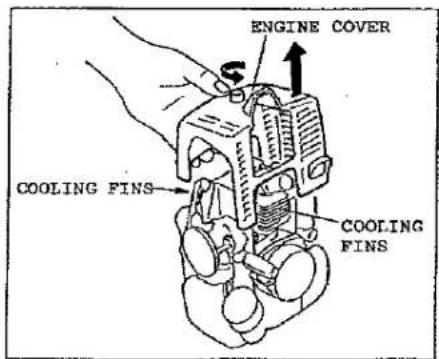
ALL MODELS: Free passage of air through the cylinder cooling fins is required to prevent poor engine performance and shortened engine life. Regularly check and clean all debris from the cooling fins by removing the engine cover (see sketch).
FUEL FILTER
ALL MODELS: The fuel filter is attached to the fuel pick-up tube inside the fuel tank. After each 25 hours of use, it should be checked for dirt or damage, and replaced if necessary. A wire with a hooked end aids in removing the filter from the tank. Avoid damaging the fuel line.

SPARK ARRESTOR
ALL MODELS: The spark arrestor should be inspected and cleaned after each 20 hours of use. The spark arrestor is installed inside the exhaust outlet of the muffler, and is secured by one screw through the side of the exhaust outlet (see sketch). Remove the screw, and pull the spark arrestor from inside the exhaust outlet tube. (If using pliers, care must be used to avoid crushing the spark arrestor flange.) Solvent and stiff brushing will usually be required for cleaning. Re-install the spark arrestor and the fastening screw.

EXHAUST MUFFLER
ALL MODELS: The muffler should be inspected and cleaned after each 100 hours of use. The engine cover must be removed for access to the muffler. Four screws (see sketch) attach the muffler cover to the muffler body. When the cover is removed, the spark arrestor is revealed in the exhaust outlet tube of the muffler cover. Remove the one screw securing the spark arrestor to the muffler cover and separate them. Clean the cover and the spark arrestor. (see instructions-Spark Arrestor.) It is not necessary to remove the muffler body from the cylinder for cleaning, BUT special care should be taken to prevent any debris from entering the exhaust ports. Use liquid gasket P/N 261910 to form the gasket between the muffler body and cover. Use Loctite P/N 261911 on the four screws attaching the cover to the muffler body. Secure the spark arrestor into place with the fastening screw.

LUBRICATION: GEARCASE
MODEL MC260S:
The gearcase should be checked for lubrication after each 30 hours of use. Remove the cutting attachment and the boss adapter (see sketch). Clean any dirt and debris from the area between the boss adapter and the gearcase. Remove the grease plug from the side of the gearcase.
While rotating the attaching shaft, inject lithium-base bearing lube (P/N 211337) through the plug hole until the gearcase is full. Re-install the boss adapter and grease plug.
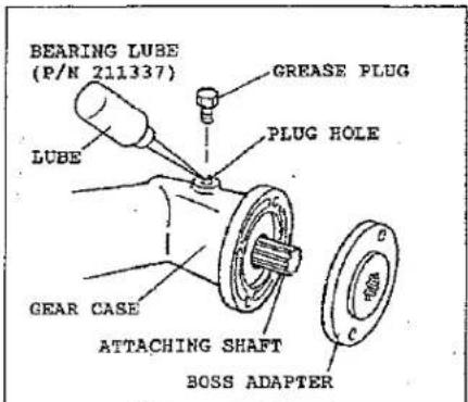
MODEL MC260E: Follow the direction for the model MC260S, except it is not necessary to remove the blade and boss adapter. Inject the lube (P/N 211337) through the plug hole until the gearcase is full.
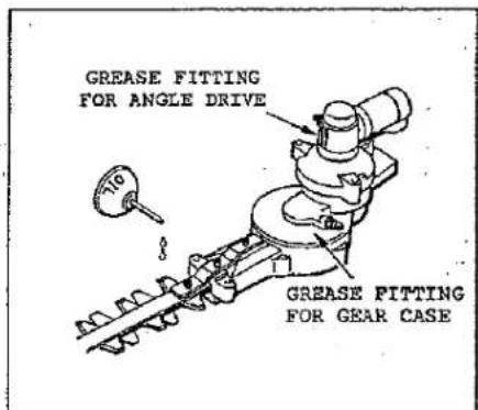
MODEL MC260D: The gearcase and angle drive should be checked for lubrication after each 10 to 20 hours of use. Grease fittings are installed into both components.(see sketch). Use #2 lithium-base bearing lubricant.
Lubrication of the cutting blades should be maintained at all times. Use a light oil (#10wt.)
LUBRICATION: FLEXIBLE DRIVESHAFT
MODELS MC260C AND MC260E:
These models contain a flexible driveshaft inside the driveshaft tube. The flexible driveshaft should be lubricated after each 30 hours of operation. Loosen the two screws on the gearcase (bearing case on MC260C) and remove the gearcase (bearing case). The inner flexible driveshaft is easily removed by gripping the end securely and pulling it from the driveshaft tube. Lubricate the entire length of the flexible driveshaft and insert it into the driveshaft tube. If the tool attachment is connected to the power unit twist the flexible shaft while pushing to insure that it seats correctly into the driveshaft coupler. Re-install the gearcase (bearing case) onto the driveshaft tube and tighten the two screws.

ADJUSTING THE CUTTING BLADES
MODEL MC260D :
Before operating the power Hedge Trimmer it is necessary to check the adjustment of the cutting blades. Blades that are too loose may vibrate, and will not provide a clean, smooth cut.

CAUTION-BLADES THAT ARE TOO TIGHT CAN CAUSE OVERLOADING WHICH MAY DAMAGE THE EQUIPMENT.
To adjust the cutting blades, refer to the illustrations and locate the tension screws.
Loosen the tension screw locknuts. Gently turn the tension screws in until snug, then turn the tension screws back out 1/4 turn. While holding the screws in place, tighten the locknuts. Liberally coat the cutting blades with light oil. Start the engine and operate the Hedge Trimmer at full speed for at least one minute. Stop the engine, and when the blades are motionless, touch the blades with your hand.


CAUTION-DO NOT TOUCH THE SHARPENED EDGES OF THE CUTTING BLADES. THE CUTTING BLADES ARE EXTREMELY SHARP AND DANGEROUS AT ALL TIMES!!
The blades may be warm, but if they are too hot to touch, loosen the tension screws 1/8 turn.
GENERAL CLEANING AND TIGHTENING
The MARUYAMA Multi-Cutter and Tool Attachments will provide maximum performance for many, many hours if they are maintained properly. Good maintenance includes regular checking of all fasteners for correct tightness, and cleaning the entire machine.

IMPORTANT!!-Be sure to clean between the gearcase and boss adapter.

STORAGE
ALL MODELS: For long-term storage of the multi-cutter and the tool attachments, perform all regular maintenance procedures and needed repairs. Empty the fuel tank. Disconnect the fuel-return tube from the carburetor, then continue to pump the primer bulb until fuel stops discharging from the fuel-return fitting. Start the engine and allow it to run until it stops. Pull the starter cord a few times to remove any excess fuel from the engine. Remove the spark plug and insert a small amount of oil. Pull the starter cord once and bring the piston to a position closest to the spark plug hole. Re-install the spark plug. Apply a thin coating of oil to the entire machine and store in a dry place.

MARUYAMA U.S., INC.
LIMITED WARRANTY STATEMENT
All Maruyama products are warranted to the original purchaser to be free from defects in material and workmanship for a period of two (2) years from the date of purchase when applied to residential use, or six (6) months from the date of purchase when applied to commercial use.
Any part(s) of Maruyama products found to be defective within the warranty period shall, at Maruyama's option, be repaired or replaced without charge. Warranty consideration is obtained by delivering any Maruyama product believed to be defective to an Authorized Maruyama Service Dealer within the applicable warranty period.
Warranty will not apply to conditions resulting from:
- Damage(s) and/or costs associated with shipping and/or transportation.
- Lack of normal maintenance, adjustments, or service required for regular use of the product.
- Modifications, service/repairs, parts or components not authorized by Maruyama.
- Normal wear, accident, abuse, neglect, misuse, negligence, improper fuels/fuel mixtures, or failure to operate or maintain the product in accordance with instructions approved by Maruyama.
Maruyama shall not be liable for any special, consequential, direct or indirect damages, and expressly states there are no implied warranties. Some states do not allow limitation of incidental or consequential damages, accordingly the above limitations and exclusions may not apply to you.
This warranty provides you with specific legal rights which may vary from state to state.
It is the owners responsibility to properly complete and mail the Warranty Registration Card. Proof of purchase and registration will be required in order to obtain warranty service.
For the name of the authorized Maruyama dealer nearest you.
CONTACT
Maruyama U.S., Inc. / 301 - 30 th Street NE, Suite 118 / Auburn, WA 98002
- INSTRUCTION MANUAL
- FOREWORD
- SAFETY INSTRUCTIONS
- MODEL IDENTIFICATION
- ASSEMBLY INSTRUCTIONS
- ENGINE AND DRIVESHAFT ASSEMBLY (POWER UNIT)
- LOOP HANDLE
- THROTTLE CABLE AND WIRING
- STRAIGHT SHAFT TOOL ATTACHMENT (MC260S)
- CURVED SHAFT TOOL ATTACHMENT (MC260C)
- HEDGE TRIMMER TOOL ATTACHMENT (MC260D)
- EDGER TOOL ATTACHMENT (MC260E)
- CONNECTING THE TOOL ATTACHMENTS TO THE POWER UNIT
- BEFORE OPERATION
- OPERATING INSTRUCTIONS
- STARTING PROCEDURE
- ENGINE OPERATION
- STOPPING THE ENGINE
- CARBURETOR ADJUSTMENT
- OPERATING THE MULTI-CUTTER AND TOOL ATTACHMENTS
- CUTTING WITH NYLON TRIMMER LINE
- USING METAL CUTTING BLADES
- HEDGE TRIMMER OPERATION
- EDGER OPERATION
- REGULAR MAINTENANCE
- AIR FILTER
- SPARK PLUG
- COOLING FINS
- FUEL FILTER
- SPARK ARRESTOR
- EXHAUST MUFFLER
- LUBRICATION: GEARCASE
- MODEL MC260S
- LUBRICATION: FLEXIBLE DRIVESHAFT
- MODELS MC260C AND MC260E
- ADJUSTING THE CUTTING BLADES
- GENERAL CLEANING AND TIGHTENING
- STORAGE
- MARUYAMA U.S., INC
- LIMITED WARRANTY STATEMENT
Merk : Maruyama
Model : MC260
Categorie : Grasmaaier