650800 - Kantoor Equip - Gratis gebruiksaanwijzing en handleiding
Vind de handleiding van het apparaat gratis 650800 Equip in PDF-formaat.

Gebruikersvragen over 650800 Equip
0 vraag over dit apparaat. Beantwoord die u kent of stel uw eigen vraag.
Stel een nieuwe vraag over dit apparaat
Download de handleiding voor uw Kantoor in PDF-formaat gratis! Vind uw handleiding 650800 - Equip en neem uw elektronisch apparaat weer in handen. Op deze pagina staan alle documenten die nodig zijn voor het gebruik van uw apparaat. 650800 van het merk Equip.
GEBRUIKSAANWIJZING 650800 Equip
equip®
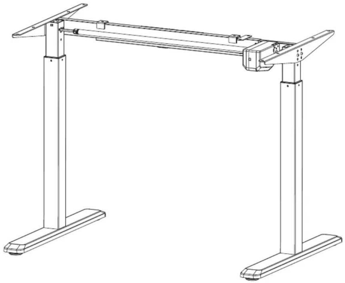
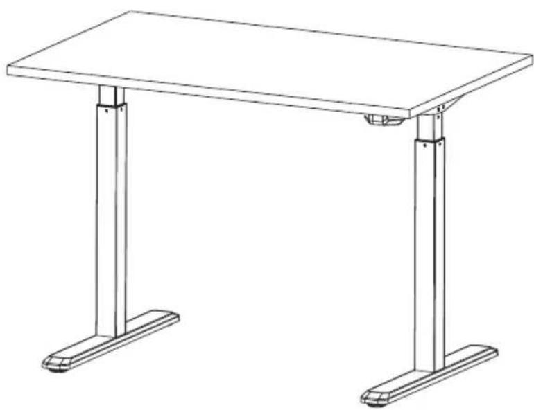
Electric Sit-Stand Desk Frame
natural_image
Technical line drawing of a two-side table frame structure with vertical supports (no text or symbols)650800 / 650801 / 650802

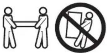
WARNING: FAILURE TO COMPLY WITH OR OBSERVE ALL ASSEMBLY, SAFETY AND OPERATION INSTRUCTIONS AND WARNINGS REGARDING THE USE OF THIS PRODUCT MA Y RESULT IN SERIOUS BODILY INJURY.
Important information
Read the entire instruction manual before you start installation and assembly.
This product is not intended for use by young children without supervision.
This product contains small items that could be a choking hazard if swallowed. Keep these items away from children.
This product is intended for indoor use only. Using this product outdoors could lead to product failure and personal injury.
This product can be used by children from 8 years old (super vised) to Adult. Users with disabilities or lack of experience and operating knowledge should be supervised and given careful instruction prior to using this product. The desktop should never be sat on and children should be prohibited from having unsupervised contact with the product.
Cleaning and user maintenance shall not be made by children without supervision.
If the supply cord is damaged, it must be replaced by the manufacturer, its service agent or a similarly qualified person in order to avoid a hazard.
IMPOR TANT: Ensure that you have received all parts according to the component checklist prior to installation. If any parts are missing or faulty, telephone your local distributor for a replacement.
QUICK TIP: DO NOT overtighten screws during installation.
CAUTION:
- Please place the product away from corrosive gas, water and dusty environment.
- Please do not disassemble all the components, otherwise, it will be seen as the withdrawn of the warranty service.

Disposal:
This marking indicates that this product should not be disposed with other household wastes throughout the EU. To prevent possible harm to the environment or human health from uncontrolled waste disposal, recycle it responsibly to promote the sustainable reuse of material resources. To return your used device, please use the return and collection systems or contact the retailer where the product was purchased. They can take this product for environmental safe recycling.

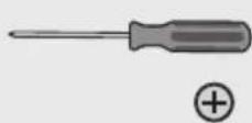
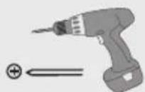
Tools Needed

Component Checklist
natural_image
Line drawing of a rectangular electronic device with internal components (no text or symbols)C (x1) control unit
natural_image
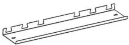
Line drawing of a metal bracket with serrated edges and mounting holes (no text or symbols)D (x1) shelf
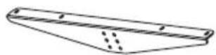
E (x2) side bracket
natural_image
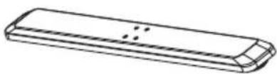
Line drawing of a rectangular electronic component with a curved base and internal structure (no text or symbols)F (x2) foot
natural_image
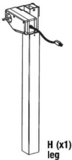
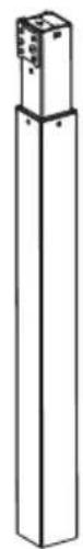
Technical line drawing of a vertical mechanical device with a cable and labeled H (x1) leg (no other text or symbols)I (x1) leg
S-A (x16)
S-B (x10)
S-C (x2)
S-D (x1)
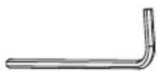
Allen key
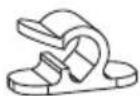
S-E (x3) cable clip
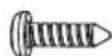
S-F (x8)
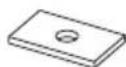
rubber pad
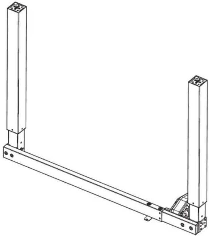
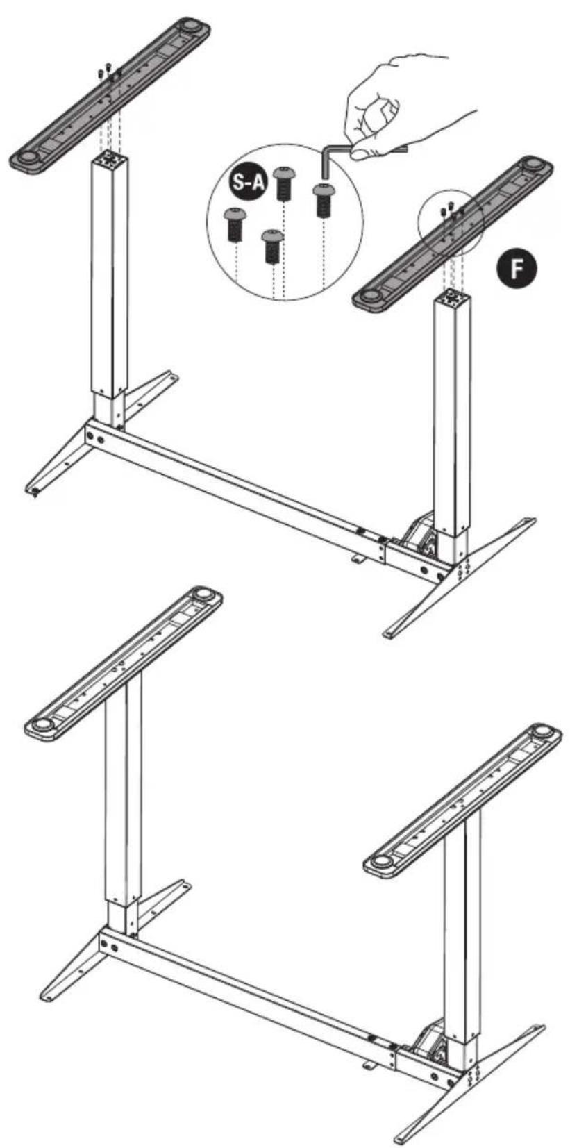
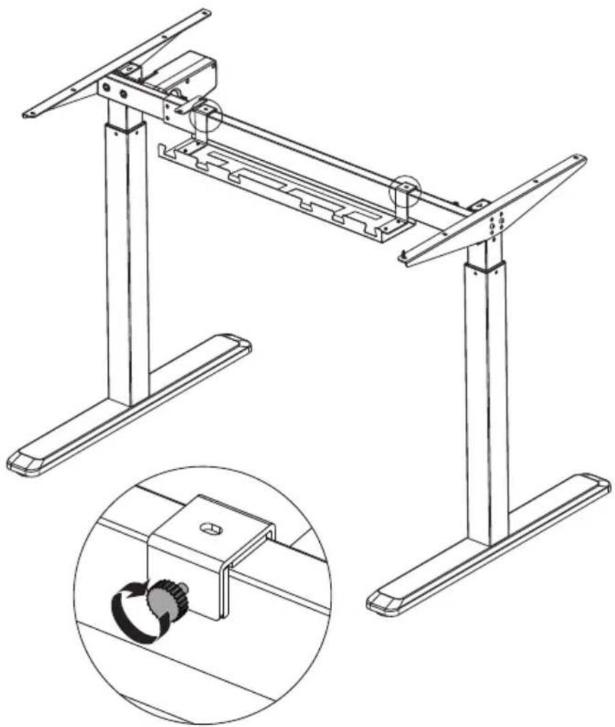
1. Assembling the Frame
- Loosen the two screws using the Allen key.
- Adjust the frame length to suit the desktop.
- Retighten all screws.
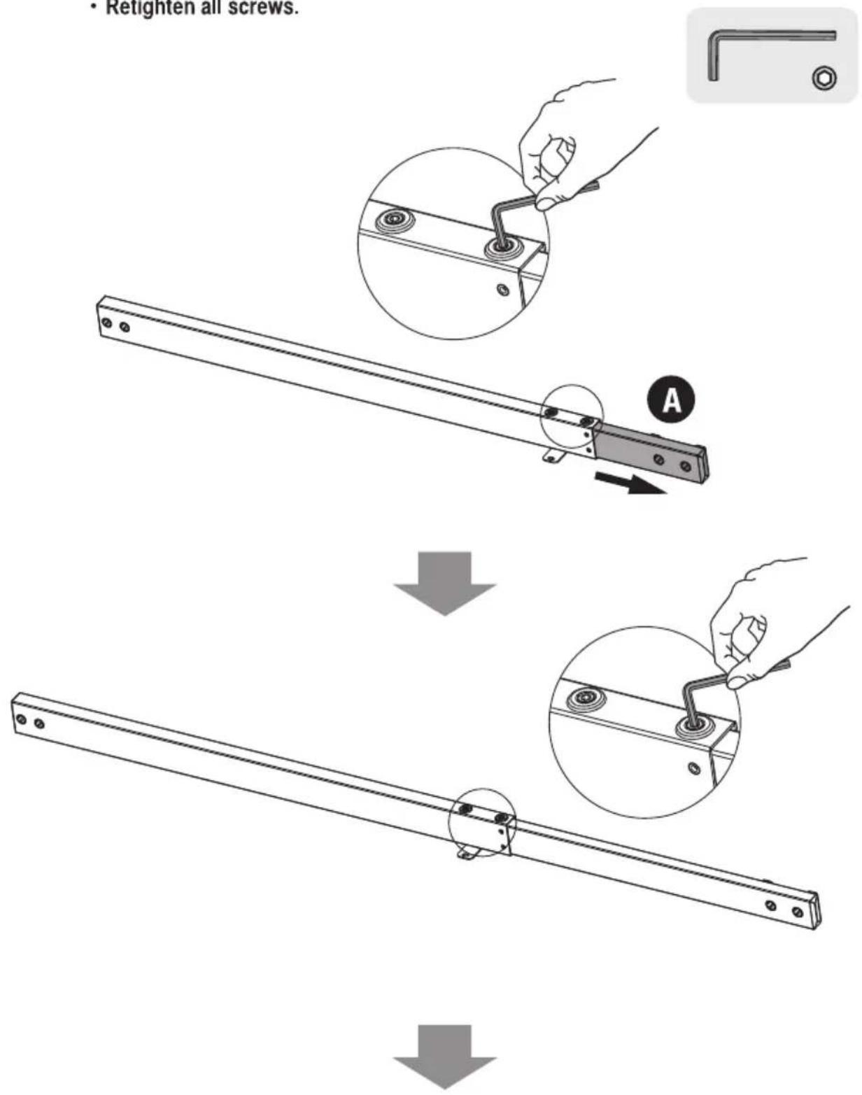
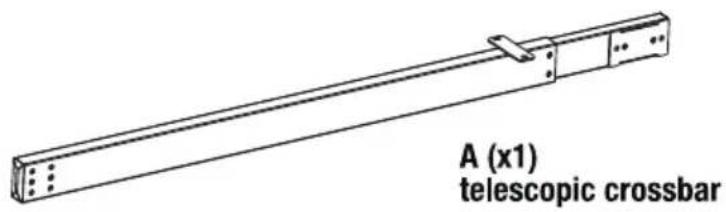
- Attach the telescopic crossbar to the legs as shown using the screws identified in the illustration.
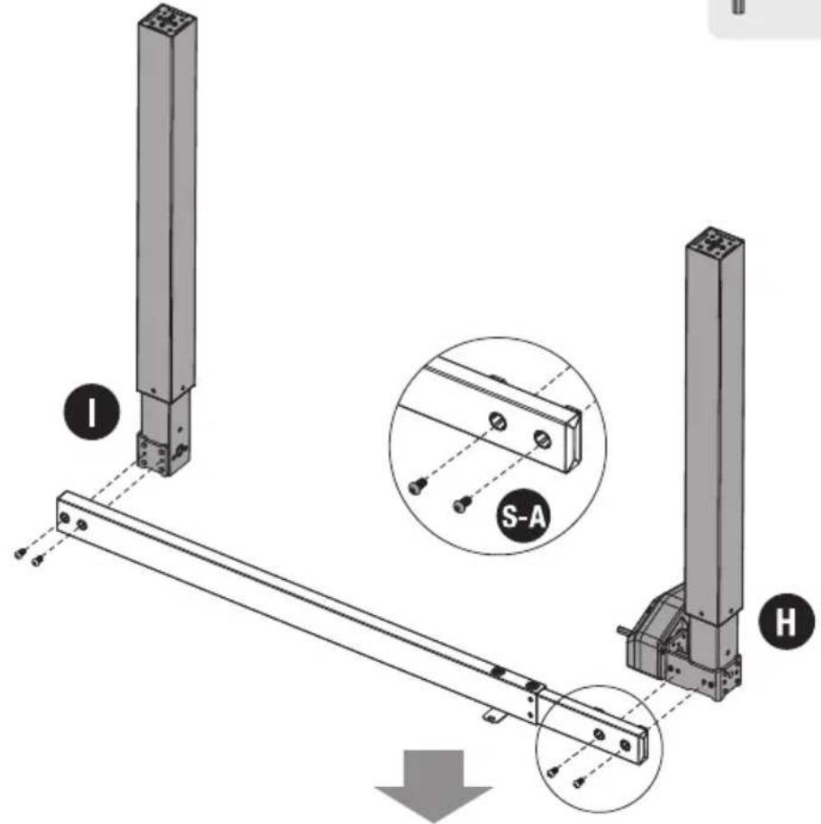
- Tighten all screws with a proper screwdriver.
natural_image
Technical line drawing of a mechanical support structure with two vertical posts and a horizontal beam (no text or symbols)2. Installing the Side Brackets
- Attach the two side brackets to both ends of the frame using the four screws and tighten all screws with an Allen key.
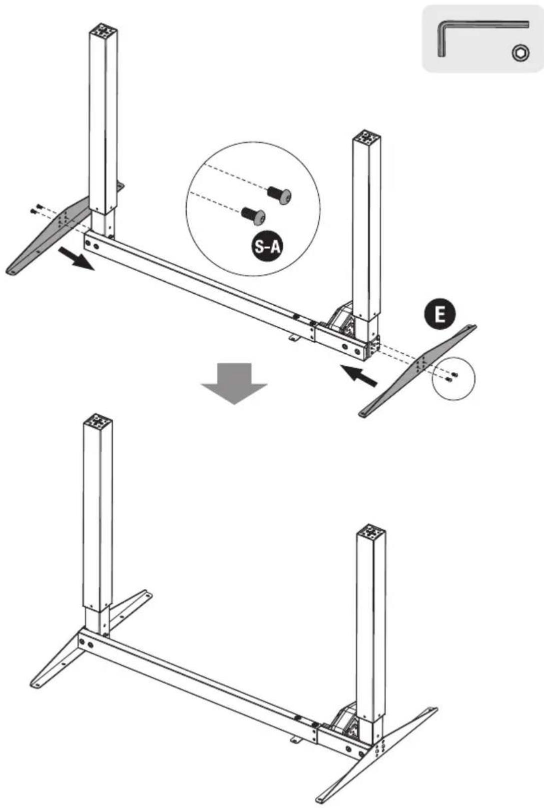
3. Installing the Feet
- With the frame upside down, place the feet on the legs as shown.
- Insert the screws as shown and fix them under the desk legs.
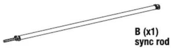
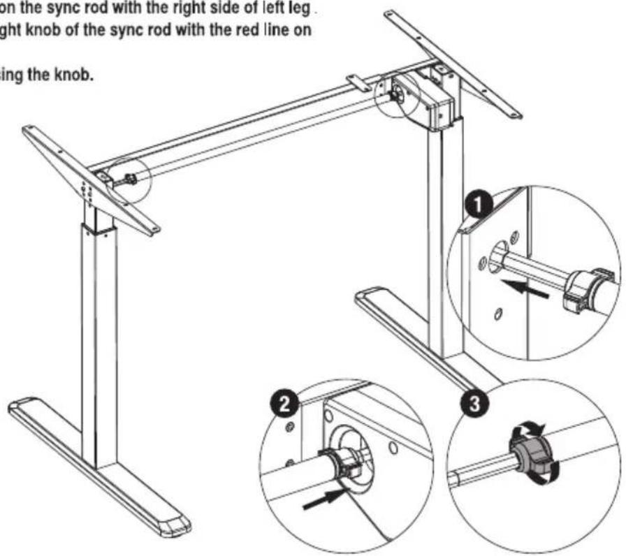
4. Installing the Sync Rod
- With the frame positioned upright, turn the knob as shown counter clockwise to loosen the sync rod.
- Adjust the sync rod to match the frame's width then.
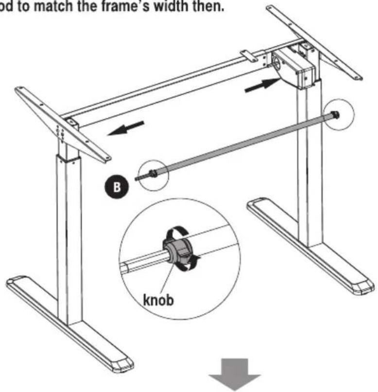
- Notice: Match the red line on the sync rod with the right side of left leg. Match the right side of the right knob of the sync rod with the red line on the rod of the motor.
- Re-tighten the sync rod using the knob.
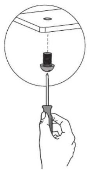
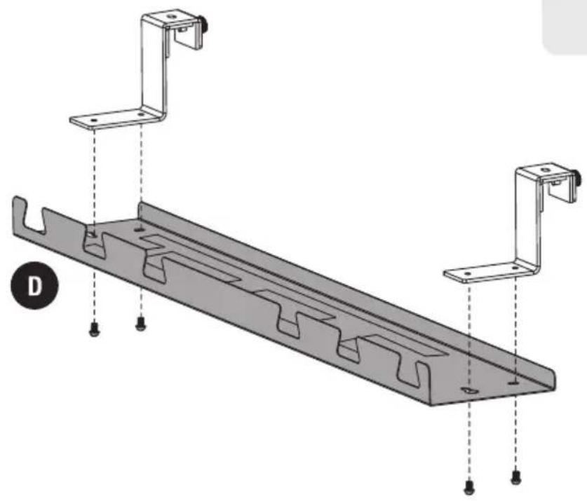
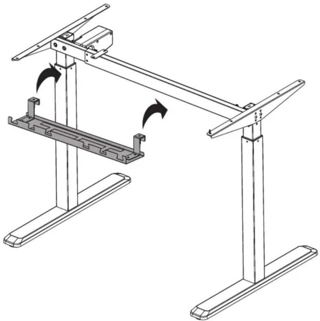
5. Installing the Shelf
- Loosen and remove the screws with a proper screwdriver.
natural_image
Illustration of a hand holding a screwdriver with a dropper inserted into a circular component (no text or symbols)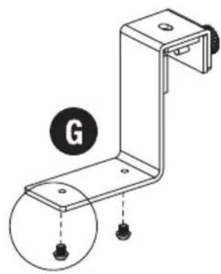
natural_image
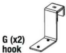
Technical line drawing of a mechanical bracket with two mounting holes and a labeled circle (G), no text or symbols present.
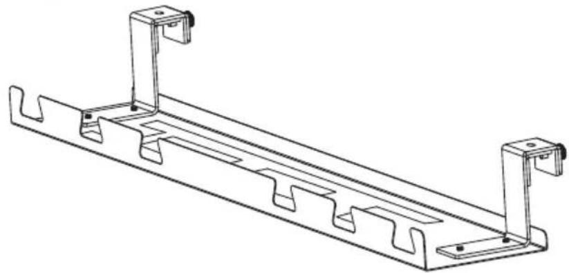
• Fix the hooks to the shelf with the previously removed screws.
natural_image
Technical diagram of a metal frame assembly with two mounting brackets and mounting holes (no text or symbols)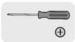
- Tighten the screws.
natural_image
Technical line drawing of a metal bracket with mounting holes and support brackets (no text or symbols)
- Hang the shelf onto the center part of the telescopic crossbar.
natural_image
Technical line drawing of a mechanical frame assembly with no visible text or symbols- Tighten the screws.
natural_image
Technical line drawing of a mechanical frame assembly with a close-up inset showing a rotating component (no text or symbols)6. Connecting the Cables
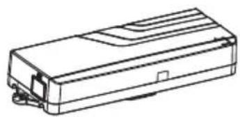
- Connect the wires to the control unit.
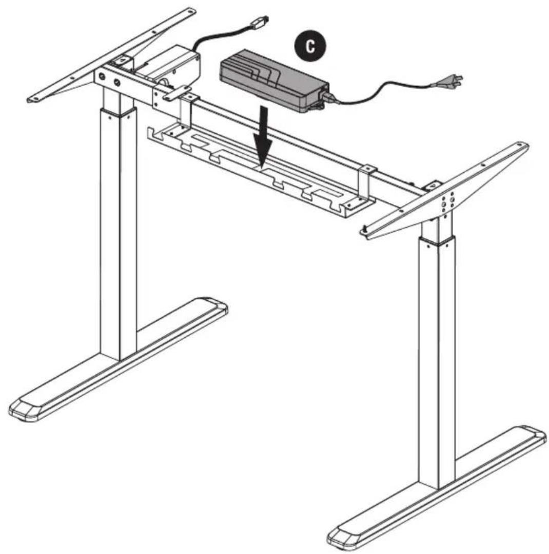
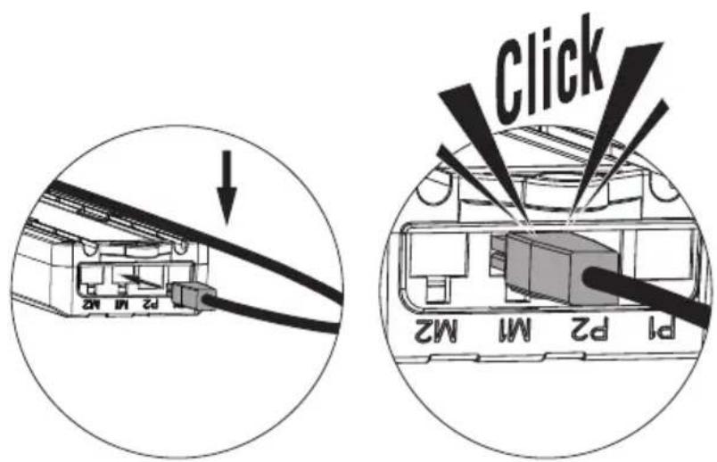
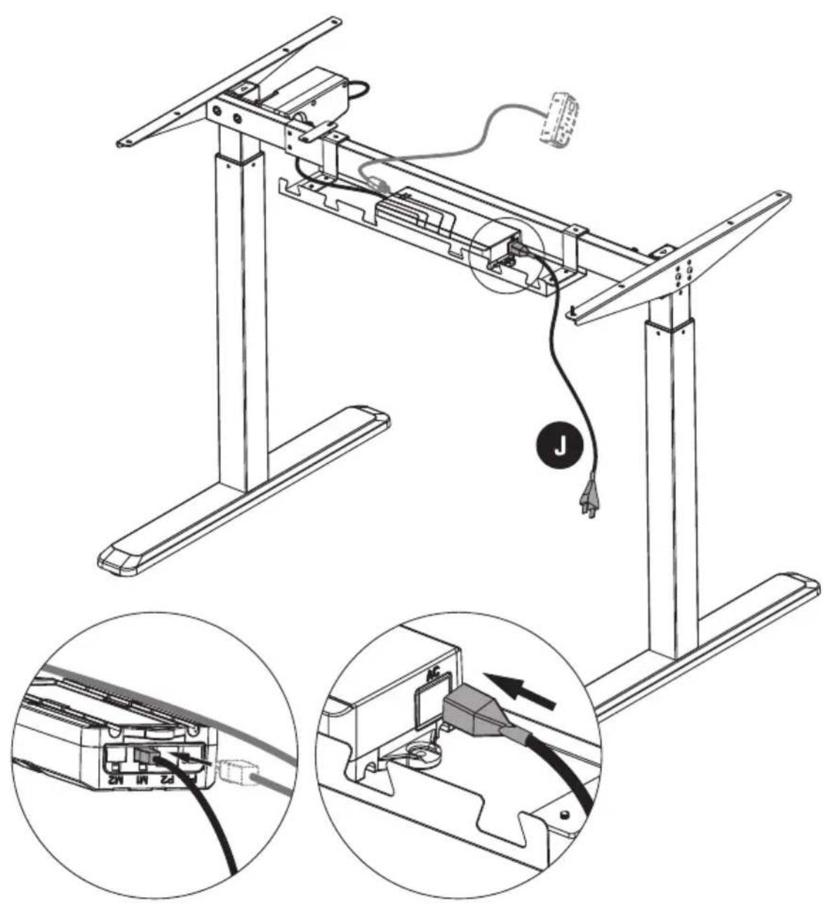
Note: Keep all cables organized.
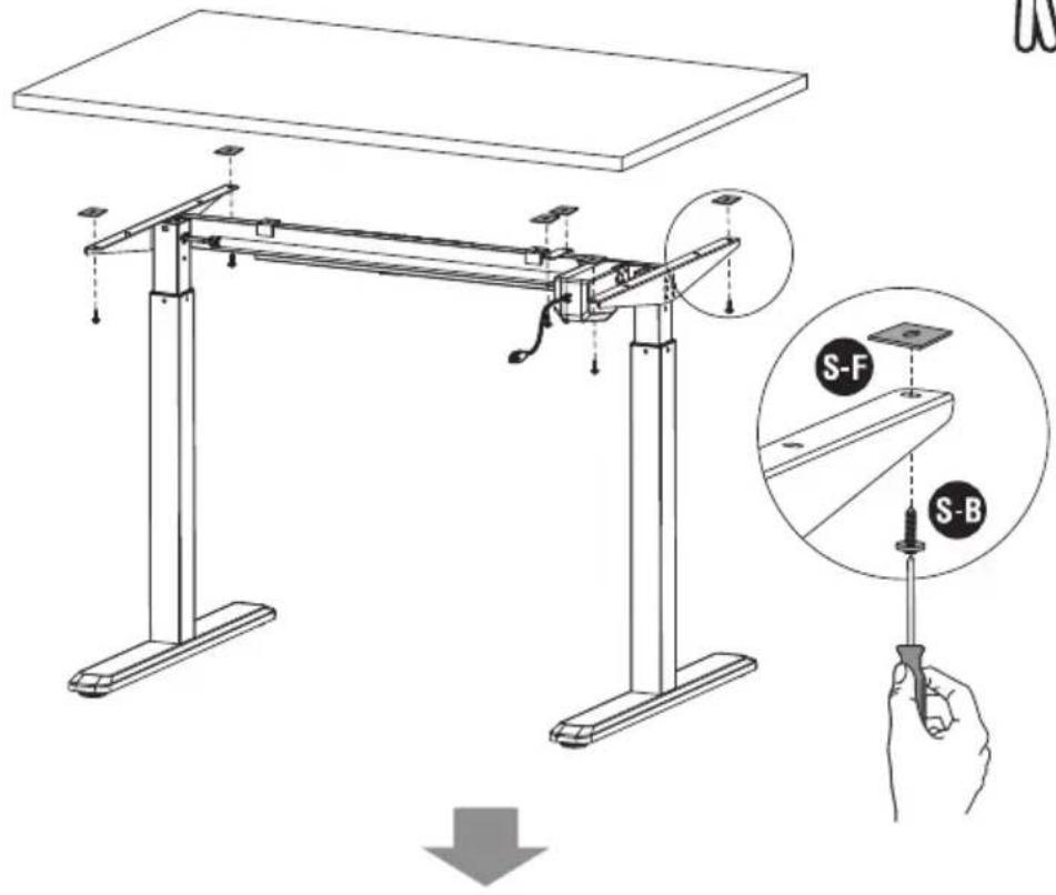
7. Installing the Desktop
- Remove the protective film from the adhesive rubber pads.
- Position the rubber pads on the side brackets as shown.
- Place the desktop on the frame and insert the desktop mounting screws.
- Tighten all screws.
natural_image
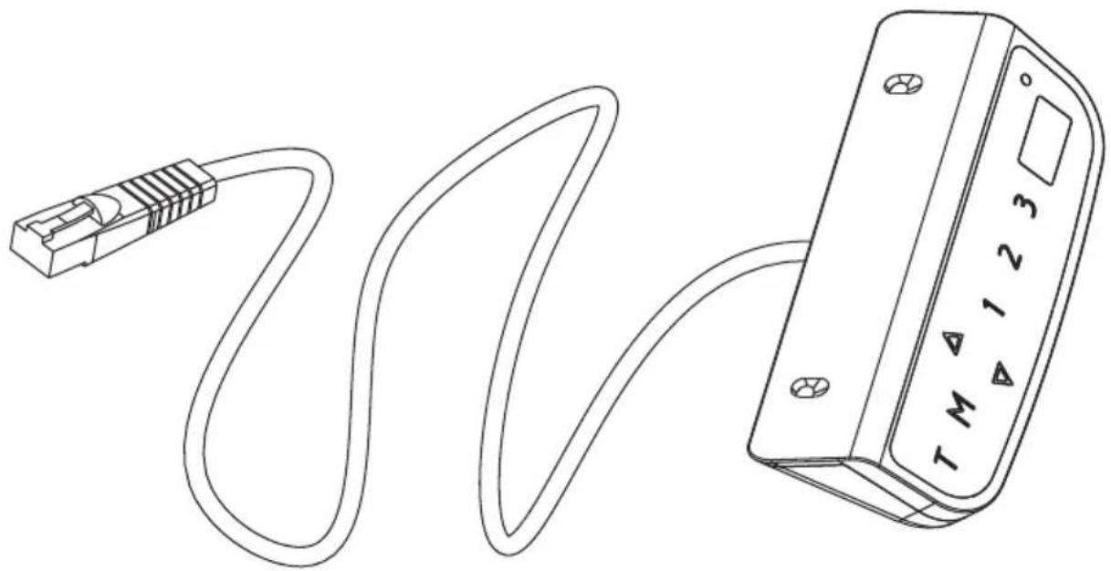
Line drawing of a two-legged table with vertical supports (no text or symbols)Digital Control Panel For Electric Height Adjustable Desk
Installation Instruction & User Guide
natural_image
Line drawing of a USB cable connected to a device with a terminal labeled T, M, 1, 2, 3 (no text or symbols on the diagram itself)Model: CT-01
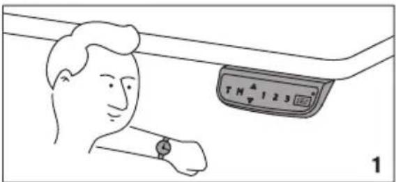
1 Operating Control Panel
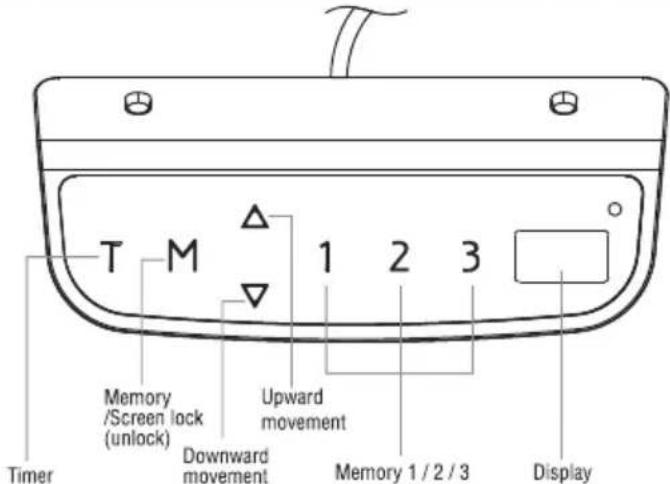
Operation Instruction:
- When the system is powered on, you will hear a beep and the existing desktop height will be displayed on the controller.
2. △ Upward movement
Downward movement
Touch the “△” or “▽” and do not release until the desk reaches the desired height. If the motor continuously operates for a relatively long period of time, the overheat protection will activate. The control panel will work normally again after approximately 20 minutes.
3. Memory Mode
To store a certain height in the controller's memory, first touch "M". The letter "S-" will be displayed. Now touch "1", "2", or "3" within five seconds to store the current height in memory. The "1", "2", or "3" buttons can each store a different height. Once in memory, you can select any of the 3 height settings found in the controller's memory by pressing the corresponding button. Touching any buttons (except for "T") will stop the automatic adjustment.
4. Reset Mode
While the unit is powered on, press the "▽" button until the desk moves into a fully lowered position, "63.0" or "73.0" is displayed on the controller. Again, press the "▽" button until "RST" is displayed on the controller. Once the display shows "62.0" or "72.5", release the "▽" button—the desk will move upward for approximately 10mm or 5mm and automatically come to a stop. After finishing the reset, the controller should display "63.0" or "73.0" which is the current height.
5. Time Reminder
To set the time reminder, press "T" found on the controller. The display will flash "0.5h" which means 0.5 hour. Press the "T" repetitively to increase 0.5 hours at a time. The maximum timer setting is two hours. The timer is set when the digit stops flashing and the light in the top right corner of the controller is on. When the timer has reached the set time, the buzzer beeps, reminding the user to adjust his/her working position. Once a timer setting has expired, the unit's timer is cancelled. To de-activate the timer, press the "T" five times until the current height is displayed and the light found in the upper right side of the controller is off.
6. Protective Standby Mode (60 Second)
If you want to prevent accidental operation, longpress "M" button for 3s to activate standby mode. The protective standby mode activates when the display shows "---". The protective standby mode will also activate when there is no operation over 60s. To turn off the standby mode, longpress the "M" button for 3s.
7. Power-saving Mode (10 Minutes)
When no actions are made for over 10 minutes, the system will enter power-saving mode. Touch any button to enter operation mode.
8. Switch measurement between cm and inch
The preset measurement shown on the display is cm. If you would like to change cm to inch, please restart the system and press the button "T" for 8 seconds. After the buzzer beeps twice, the measurement is successfully reset. If you would like to switch inch back to cm, please restart the system and press the button "T" for 8 seconds. After the buzzer beeps once, the system is successfully switched to cm measurement again.
Trouble Shooting
Below are the possible error codes that may be displayed on the control panel.
| Error Code | Description |
| ER1 | Overload in downwards direction has occurred and needs to be restart power. |
| ER2 | Over-heating in the controller has occurred and needs to cool. |
| ER3 | Motor cable connection fault and needs to be reset. |
| ER4 | Both legs have different heights and need to be reset. |
| ER5 | Motor fault |
Note:
- Self-protection function: the unit will enter protective mode if the system operate in excess of two minutes with "HOT" on the controller display. The system will reset and return to normal operation after approximately 18 minutes.
- Overload protection mode: while operating, if the load on the desk is over weight capacity, the system will enter into an overload protection mode. This will protect the system from damages caused by exceeding weight. When this happens, the desk will move downward approximately 30mm and come to a stop with the current height displayed.
- Attention: NEVER remove or turn off the power in order to reset the unit when it is in a protective mode or "HOT" state.
- Please reset in case two legs are different in height.

Repair Guide
In Front

This repair guide intents to help you identify and solve the minor problems caused by unusual operation of the electric system of our sit-stand desk. The simple procedures in this manual are easy to follow and capable of solving the most problems happened in everyday use.
Errors
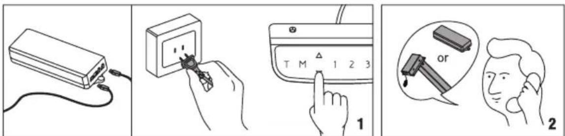
1. Display Shows ER1
When ER1 is shown on the control panel, please check if the load is over weight capacity. If not, please reconnect the desk to power, and restart the system. If ER1 is still shown on the panel, please contact your point of purchase for service or repair to your unit.
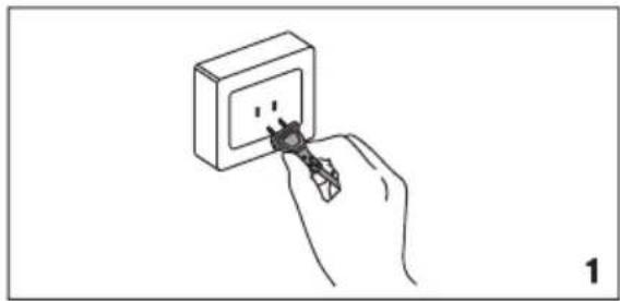
natural_image
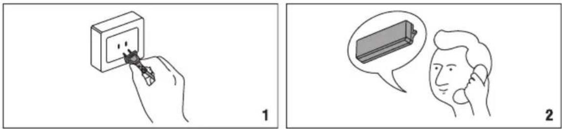
Hand inserting a plug into an electrical socket (no text or symbols visible)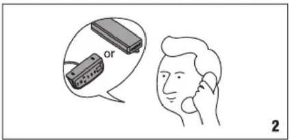
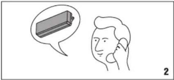
2. Display Shows ER2
Your desk is in thermal protection mode should ER2 appear on the control panel. This is normally nothing to worry about, and usually is an indication that the system has experienced above-normal operating temperature due to a number possibilities including environment, desktop weight, or activity that is above rated specifications. Allow your desk to cool down and remain idle for approximately 20 minutes and the ER2 continue to be displayed on the control panel after the allotted time, please contact your point of purchase for service or repair to your unit.
natural_image
Illustration of a person holding a phone to their ear, with a thought bubble showing a battery (no text or symbols present)3. Display Shows ER3/ER4/ER5
When ER3/ER4/ER5 appears on the control panel, please reconnect the motor cords to the control unit. Then, reconnect the desk to power, and press down button to reset the system. If ER3/ER4/ER5 still appears, please contact your point of purchase for service or repair to your unit.
4. Display Shows Control Panel Problems
If the control panel has no response or can't adjust the desk, please contact your point of purchase to replace the control panel after confirming the desk is properly connected to power. If the new control panel works, please contact us to replace the original control panel. If the desk still doesn't work, please contact your point of purchase for service or repair to your unit.
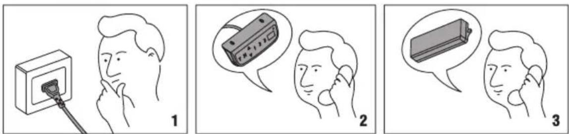
5.Can't Operate
If the desk doesn't work, after confirming the control panel works properly, please turn the power off, and restart the system. If it still doesn't work, please contact your point of purchase for service or repair to your unit.