SAS-CAM9100 - Bewakingscamera KONIG - Gratis gebruiksaanwijzing en handleiding
Vind de handleiding van het apparaat gratis SAS-CAM9100 KONIG in PDF-formaat.

Gebruikersvragen over SAS-CAM9100 KONIG
0 vraag over dit apparaat. Beantwoord die u kent of stel uw eigen vraag.
Stel een nieuwe vraag over dit apparaat
Download de handleiding voor uw Bewakingscamera in PDF-formaat gratis! Vind uw handleiding SAS-CAM9100 - KONIG en neem uw elektronisch apparaat weer in handen. Op deze pagina staan alle documenten die nodig zijn voor het gebruik van uw apparaat. SAS-CAM9100 van het merk KONIG.
GEBRUIKSAANWIJZING SAS-CAM9100 KONIG
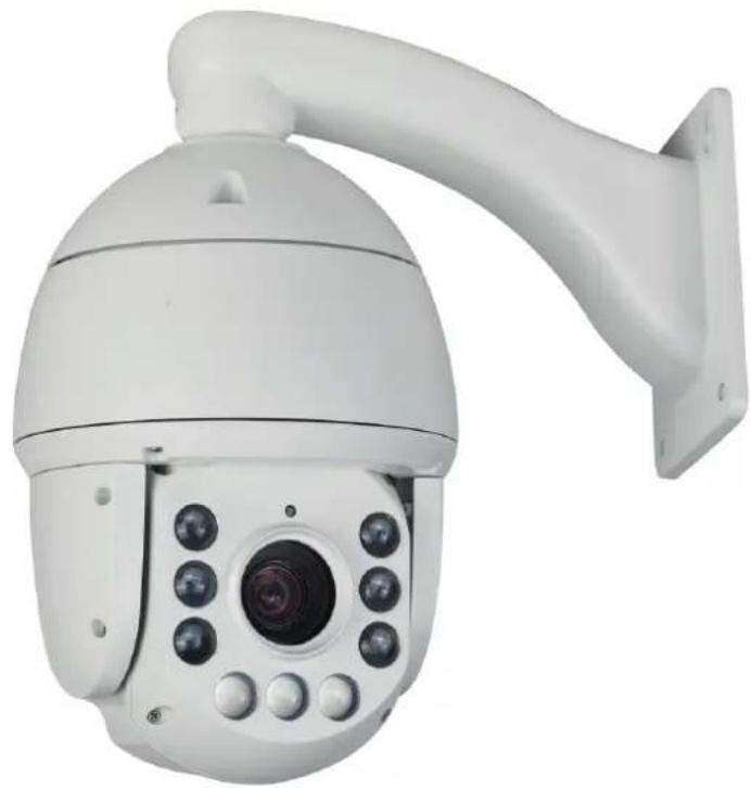
Operation Instruction for Smart Infrared High-speed Dome Camera
natural_image
White security camera with multiple sensors mounted on a wall (no visible text or symbols)Preface
We express our sincere thanks to you for choosing our product, and will do our best to provide the best services for you.
This instruction is only for reference, and will be upgraded in accordance with the improvement of our product. Therefore this instruction is subject to change without prior notice. The updated contents will be added in the updated version of this manual.
If you find inaccurate technical detail, the description unmatched production function or operation, or misprint, we appreciate that you give us your comments and feedback in time, and we will take method to improve and enrich this instruction.
Contents
Chapter 1 Overview....2
1.1 Brief introduction and application....2
1.2 Product features.... 2
1.3 Technical indicators....4
Chapter 2 Hardware installation instruction....5
2.1 Setting of dial switch....5
2.1.1 Position of dial switch....5
2.1.2 Address setting.... 5
2.1.3 Power connection....6
2.1.4 Connection of control line....7
2.1.5 Connection of Video line....7
2.1.6 Settingof Baudrate....7
Chapter 3 Operation instruction....7
3.1 Mapping table for preset location....8
3.2 keyboard operation.... 12
3.2.1 Preset location scan.... 12
3.2.2 Area scanning.... 12
3.2.3 Pattern scanning....13
3.3 Menu set.... 13
3.3.1 Basic menu operation.... 13
3.3.2 Menu set.... 13
3.3.3 System information.... 14
3.3.4 Camera setting 1....14
3.3.5 Camera setting 2....14
3.3.6 Privacyshelter....15
3.3.7 Infrared setting....15
3.3.8 Auxiliary setting.... 15
3.3.9 Scanning set....16
3.3.10 Title set.... 16
3.3.11 Alarm linkage.... 17
3.3.12 Language setting.... 17
3.3.13 Defaulted setting.... 17
Chapter 4 Simple trouble elimination....18
Safety caution
Warning: User shall be reminded to avoid the risk including potential deaths or severe injuries.
- Please refer to the ambient requirement for equipment when installation; do not install this equipment in the environment with too much moisture, much dust and much smoke dust (which may result in fire or electric shock).
- In case that this equipment emits abnormal smell or smoke, please immediately stop it, shut off the power, and contact the supplier (otherwise, this equipment may result in fire or electric shock).
- During cleaning this equipment, do not directly spray water on the parts of this equipment (which may result fire or electric shock).
- It is avoided to place this equipment near heat source (otherwise, the fire risk is potential).
- It is forbidden to store, install and use this product in danger areas with inflammable or explosive substance.
Notice: User shall be reminded to avoid the risk including potential injuries or property loss.
- During transportation, storage and installation, heavy load, violent vibration and immersion shall be prevented to avoid the damage of this equipment.
- This equipment shall be in place which is far away from the area with vibration or magnetic field interference.
- Before move or reinstall this equipment, please be sure that the power is shut off.
- This equipment shall be installed at the site with good ventilation.
- In case that this equipment does not work normally, please contact supplier, and do not disassemble or reform this equipment (the manufacturer will not bear any responsibility for the problem resulted from unapproved reformation or repair.
- During cleaning the surface of this equipment, do not use chemical cleaning agent, which may result in the deformation of equipment surface or damage of covering
layer.
- Do not make the camera shoot the object giving out strong light, whether it is in or out of service; it is forbidden to make the camera shoot sun or other bright object, otherwise, the CCD of camera will be permanently damaged.
Chapter 1 Overview
1.1 Brief introduction and application
1.1.1 Main characteristics
Infrared functions:
- Minimum luminance Olux
- Highly effective infrared array is adopted with low power consumption (domestic infrared lamp≥100m, MSRAM infrared lamp ≥130m)
- Infrared lamp and magnification distance matched calculation method adjust the matched angle of infrared lamp and lens outgoing according to the magnification and distance, so as to make the image reach ideal status.
- Thermal treatment device is built in it to reduce the temperature of dome cavity and prevent against frosting of the dome cover.
- Constant current design makes the service life of infrared lamp as long as 30,000 hours.
System function:
- 1/4" Sony high-performance CCD is used with clear image.
- Precise motor driving, quick reaction, stable operation and the precision deviation is less than 0.1 degree; no image vibration under any speed.
- Three-dimensional positioning function supported, and clicking traceability and amplification by coordinating NVR and client end software
- Multi-language menu and operation prompt function supported with friendly user's interface
- No data loss after interruption
- Interruption status memory status supported; returning to the holder and mirror status before interruption after being electrified again
- Fiber modulus access supported (optional)
- Built-in temperature sensor supported and temperature within the dome can be displayed (optional)
- Lightning, shock and surge resistance supported
- Outdoor dome reaches IP66 protection grade
- 3D digital noise reduction supported
- Timely task presetting point/pattern scan/cruise scan/horizontal scan/vertical
scan/random scan/frame scan/panoramic scan supported
Movement function:
- Automatic diaphragm, automatic focus, automatic white balance, backlight compensation, wide dynamic and low luminance (colorful/black and white) automatic/manual switch function supported
- Privacy shelter supported
Holder function:
- 360° continuous rotation horizontally, 0°-90° vertically, automatic rollout supported with blind monitoring area
- The maximum speed for horizontal presetting point is 300°/s while for the vertical presetting point is 240°/s
- The horizontal and vertical speed of manipulation are 0.1° -160°/s and 0.1° -120°/s respectively
- 255 preset location supported with the function of presetting point video freezing
- 4 preset location scanning supported and 32 preset locations can be set for each one
- 4 pattern scanning supported with no less than 200 orders for each path
- Proportional zoom function supported and rotation speed can be adjusted automatically according to the lens zoon times
- Watch function supported, preset point/pattern scan/cruise scan/horizontal scan/vertical scan/random scan/frame scan/view scan/view traceability/cruise traceability can be called automatically after the remaining the designated time under free status (including the free status entered after being electrified)
- (Optional) alarm function supported, 2-circuit built in, alarm linkage supported, preset point/cruise scan/pattern scan/SC card shooting/trigger switching value output/client electronic map can be called after alarming
Network function: (Optional)
- H.264 video compression algorithm and the latest Davinci processing chip and platform with TI high performance ratio are adopted with reliable and stable performance.
- Ethernet control and simulation access supported
- See and control image through IE browser and client software
- SDHC card and standard SD card storage (optional) supported
- Three-level user's authority management supported
- Dual stream technology supported
- Multiple network protocols, 1 circuit audio input and output supported
1.1.2 Application
It can be widely used in the place without light or with weak light where high-speed monitoring in large scope is required, such as river, forest, road, railway, airport, port, watch, square, park, scenic spot, street, station, large stadium and external boundary of living quarters, etc. As a high-end monitoring product, the
integrated smart high-speed dome camera features strong, stable and reliable function, easy operation and installation, etc., has a good cost performance, and has become the mainstream product in monitoring industry. This camera has many functions, such as fast trace, 360° unlimited rotation, 180° automatic overturn, area scan, preset location scan, pattern scan, screen menu, etc, especially the remote head driven by stable and reliable step motor may precisely catch the target and has several speeds. This camera applies to watching the moving target in a big area, and has the performance that several fixed cameras cannot achieve. Therefore it is widely used in various areas such as airport, station, superstore, political-legal organ, bank, enterprise, warehouse, hospital, etc.
1.2 Product features
● Supporting CVBS standard definition video signal output;
● Driven by accurate step motor, with stable running and low noise;
● Up to 255 programmable preset locations;
- Several scan modes such as area scan, preset location scan, pattern scan, etc.;
● Multi-function Chinese-English menu with flexible and easy configuration;
- Vertical and automatic overturn function can realize the continuous watch without blind area;
- Telephoto and limit speed function provides a clear and stable monitoring picture;
● Self-adaptive baud rate and communication protocol;
● Non-polarity RS485 supports broadcast address and soft address;
● Supporting failure detection indication for RS485 communication;
● Infrared dome supporting night vision function.
● IP66Protection grade: IP 66
- Ultralow power consumption and ultra-strong stability.
1.3 Technical indicators
| No. | Item | Technical indicator |
| 1 | Video standard | PAL/NTSC |
| 2 | Horizontal rotation scope | 360° continuous rotation |
| 3 | Vertical rotation scope | 0° ~ 90° automatic overturn |
| 4 | Horizontal operation speed | 0.1~ 300° /s |
| 5 | Vertical operation speed | 0.1~ 240° /s |
| 6 | Preset location running speed | 300° /s |
| 7 | Preset location accuracy | ±0.10° |
| 8 | Preset locations | 255 |
| 9 | Menu operation | Supporting multi-language (Chinese and English) |
| 10 | Function display | Yes |
| 11 | Coordinate display | Yes |
| 12 | Communication failure detection and indication | Yes (error indications such as baud rate error, address error, protocol unmatched, etc.) |
| 13 | Editable area to be blocked | 8 areas |
| 14 | Preset location scan | 4 (32 preset locations for each routine) |
| 15 | Routine scan | 4 (left and right boundaries, speed and area name can be set) |
| 16 | Pattern scan | 4 (there are no less than 200 instructions for each routine) |
| 17 | Watch location function | Yes |
| 18 | Timing running | Supporting 8 time intervals |
| 19 | Integrated protocol | PELCO-D, PELCO-P, Industrial protocol, DH-SD1, YAAN self-adaption |
| 20 | Communication baud rate | Self-adaption 2400/4800/9600 bps |
| 21 | RS485 | Positive and negative polar |
| 22 | Telephoto and limit speed | Yes |
| 23 | Power-off memory | Yes |
| 24 | Screen freeze | Yes |
| 25 | Compatible camera | Automatic identification(SONY / HITACH / CNB/SAMSUM) |
| 26 | Infrared night vision function | Visual range (domestic infrared lamp ≥100 米, OSRAM infrared lamp ≥130m) |
| 27 | Protection grade | IP66 |
| 28 | Lightning protection | 3000 V |
| 29 | Working temp. | -35°C~+60°C |
Chapter 2 Hardware installation
2.1 Setting of dial switch
2.1.1 Position of dial switch
Dial switch is a 8-digit dial switch SW1. As shown in the figure below.

natural_image
Red electronic component with pin headers and terminal labels (no readable text or symbols beyond markings)2.1.2 Address setting
The address of dome can be set in two ways:
- Address dial switch: when the soft address is closed, the dome address will be determined by the dial switch.
- Soft address: after the soft address is opened through menu, the address dial switch can not work any more; the defaulted soft address will be closed.
- Broadcasting address: the fixed broadcasting address of dome is 100; no matter how the dome address is set, key DVR is able to control the dome through 100 address.
Comparison list of address dial switch:
| Address | 1 | 2 | 3 | 4 | 5 | 6 | 7 | 8 |
| 0 | OFF | OFF | OFF | OFF | OFF | OFF | OFF | OFF |
| 1 | ON | OFF | OFF | OFF | OFF | OFF | OFF | OFF |
| 2 | OFF | ON | OFF | OFF | OFF | OFF | OFF | OFF |
| 3 | ON | ON | OFF | OFF | OFF | OFF | OFF | OFF |
| 4 | OFF | OFF | ON | OFF | OFF | OFF | OFF | OFF |
| 5 | ON | OFF | ON | OFF | OFF | OFF | OFF | OFF |
| 6 | OFF | ON | ON | OFF | OFF | OFF | OFF | OFF |
| 7 | ON | ON | ON | OFF | OFF | OFF | OFF | OFF |
| . . . | ||||||||
| 250 | OFF | ON | OFF | ON | ON | ON | ON | ON |
| 251 | ON | ON | OFF | ON | ON | ON | ON | ON |
| 252 | OFF | OFF | ON | ON | ON | ON | ON | ON |
| 253 | ON | OFF | ON | ON | ON | ON | ON | ON |
| 254 | OFF | ON | ON | ON | ON | ON | ON | ON |
| 255 | ON | ON | ON | ON | ON | ON | ON | ON |
2.1.3 Power connection
Note: Please inspect the rated voltage and current carefully; the rated voltage and current are as follows:
| Rated voltage (V) | Scope of rated voltage | Current |
| DC 12V | Positive and negative 10% | >4A |
2.1.4 Connection of control line
PTZ control: RS-485 control line is connected to the control keyboard or digital video recorder. If several cameras are controlled at the same time, RS-485 control line shall be set in parallel.
Note: ① RS-485 control line should be connected correctly (positive and negative)
② The protocol and Baud rate controlling keyboard or digital video recorder can be set arbitrarily
③ Several cameras in monitor network can be set with different dome addresses.
2.1.5 Connection of video line
BNC joint is used to connect video signal line directly
2.1.6 Setting of Baud rate
Baud rate 2400, 4800, 9600 recognized automatically
Chapter 3 Operation instruction
3.1 Mapping table for preset location
| Preset location | Function |
| 95+CALL | Entering the main menu |
| XXX+PRESET | Saving some presetting point |
| XXX+CALL | Calling some presetting point |
| 40+CALL | Operating the first group of preset location scanning |
| 41+CALL | Operating the second group of preset location scanning |
| 42+CALL | Operating the third group of preset location scanning |
| 43+CALL | Operating the fourth group of preset location scanning |
| 44+CALL | Setting the left boundary of area scanning 1 |
| 45+CALL | Setting the right boundary of area scanning 1 |
| 46+CALL | Setting the left boundary of area scanning 2 |
| 47+CALL | Setting the right boundary of area scanning 2 |
| 48+CALL | Setting the left boundary of area scanning 3 |
| 49+CALL | Setting the right boundary of area scanning 3 |
| 50+CALL | Setting the left boundary of area scanning 4 |
| 51+CALL | Setting the right boundary of area scanning 4 |
| 52+CALL | Operating area scanning 1 |
| 53+CALL | Operating area scanning 2 |
| 54+CALL | Operating area scanning 3 |
| 55+CALL | Operating area scanning 4 |
| 56+CALL | Starting the setting of pattern scan |
| 57+CALL | Saving the setting of the first group of pattern scanning |
| 58+CALL | Saving the setting of the second group of pattern scanning |
| 59+CALL | Saving the setting of the third group of pattern scanning |
| 60+CALL | Saving the setting of the fourth group of pattern scanning |
| 61+CALL | Operating the first group of pattern scanning |
| 62+CALL | Operating the second group of pattern scanning |
| 63+CALL | Operating the third group of pattern scanning |
| 64+CALL | Operating the fourth group of pattern scanning |
| 65+CALL | Starting 360° continuous rotation |
| 67+CALL | Arming of alarming input 1 (for the machines with this function only) |
| 68+CALL | Arming of alarming input 2 (for the machines with this function only) |
| 69+CALL | Disarming of alarming input 1 (for the machines with this function only) |
| 70+CALL | Disarming of alarming input 2 (for the machines with this function only) |
| 71+CALL | Starting alarming output (for the machines with this function only) |
| 72+CALL | Closing alarming output (for the machines with this function only) |
| 75+CALL | Starting the display of status column |
| 76+CALL | Closing the display of status column |
| 77+CALL | Starting vertical flip |
| 78+CALL | Closing vertical flip |
| 79+CALL | Starting guarding function |
| 80+CALL | Closing guarding function |
| 81+CALL | Starting the privacy shelter grid(for the machines with this function only) |
| 82+CALL | Closing the privacy shelter grid(for the machines with this function only) |
| 83+CALL | Starting backlight compensation (for the movement with this function only) |
| 84+CALL | Closing backlight compensation (for the movement with this function only) |
| 85+CALL | Starting image freezing function(for the movement with this function only) |
| 86+CALL | Closing image freezing function(for the movement with this function only) |
| 87+CALL | Starting image mirror function(for the movement with this function only) |
| 88+CALL | Closing image mirror function(for the movement with this function only) |
| 89+CALL | Automatic color-to-black function(for the movement with this function only) |
| 90+CALL | Starting color-to-black function(for the movement with this function only) |
| 91+CALL | Closing color-to-black function(for the movement with this function only) |
| 92+CALL | Closing wide dynamic(for the movement with this function only) |
| 93+CALL | Automatic wide dynamic(for the movement with this function only) |
| 94+CALL | Manual wide dynamic(for the movement with this function only) |
| 95+CALL | Entering the main menu |
| 97+CALL | Starting image rollover(for the movement with this function only) |
| 98+CALL | Closing image rollover(for the movement with this function only) |
| 101+CALL | Defaulted setting |
| 102+CALL | Switch manual operation speed (fast, slow and medium) |
| 103+CALL | Switching linear scanning speed (fast, slow and medium) |
| 105+CALL | Starting digital zoom |
| 106+CALL | Closing digital zoom |
| 107+CALL、108+CALL | Calling 107 followed by 108 and restarting the dome |
| 109+CALL | Starting communication fault indication |
| 110+CALL | Closing communication fault indication |
3.2 keyboard operation
3.2.1 Preset location scan
- Set preset location scan: Preset location scan routine can be set using 2 ways:
*See "Menu set -> Scan set"
* There are total 4 preset location routines, and 32 preset locations can be set. The 40^th and 43^rd preset locations are in turns used to set and call the 1^st and 4^th preset location routines:
1) Execute the command of setting 40^th preset location to enter the set status;
2) Call the desired set option to the preset location in routines, such as the first, the second, etc.;
3) Wait a desired time to stay (the interval time between two location), and do not conduct any operation;
4) Call next routine that you want to set to preset location; if there are unused preset location, add it into routine, execute in looping way the 3) and 4), or execute 5), and the set is over.
5) Execute the command of setting 40^th preset location, and save the set and exit; in addition to calling preset location, executing any command other than such as up, down, right or left, does not need to be saved before exit.
- Run preset location scan: call 40^th - 43^rd preset locations to run 1^st - 4^th group preset scan location series.
3.2.2 Area scanning
Setting of area scanning
- Setting of the left boundary: dome is controlled to ideal position and preset location 44 is called to set the left boundary of Region 1
- Setting of the right boundary: dome is controlled to ideal position and preset location 45 is called to set the right boundary of Region 1
- Setting of scanning speed: see "menu set->auxiliary set"
- Setting of regional title: see "menu set->title set"
Operating area scanning
- Call the preset location 52-55 to operate area scanning path 1-4 respectively
- Dome rotates between the set right and left boundary according to the set speed and the screen displays the corresponding regional title.
3.2.3 Pattern scanning
Setting of pattern scanning
- Call preset location 56 to start setting pattern scanning
- Operate "up, down, left, right, WIDE, TELE, NEAR, FAR, CLOSE and Open on the dome.
- Call preset location 57-60 to save the 1-4 pattern scanning
Operation of pattern scanning
Call the preset location 61-64 to operate pattern scanning path 1-4 respectively
3.3 Menu set
3.3.1 Basic menu operation
- Press control keyboard or use matrix to execute the command of "call 95^th preset location" to enter and set main menu;
- After main menu page appears, press "up or down" icon to move the cursor to the submenu option to be set, and press "right" icon to enter this submenu setting page;
- After submenu page appears, press "up or down" icon to move the cursor to the option to be set, and press "right" icon to change or set the content of this option;
- The content of option normally falls two type, one is digit type, another is list type. The blink indication means that the content of option can be changed. For digit type, press "left or right" icon to select the input location, press "up or down" icon to modify the value, and move the cursor to the last digit and press "right" to confirm and quit option setting; for list type, press "up or down" to modify the content of option, and press "right" to confirm and quit option setting.
3.3.2 Menu set
Main menu
- System information: check dome information (such as version,
- address, communication, etc.)
- Camera setting: set the camera parameters.
- Privacy shelter: set the privacy shelter functions of camera.
- Infrared setting: set infrared lamp function of camera.
- Auxiliary setting: set some auxiliary parameters of the dome.
- Scanning setting: set the scan sequence of preset location.
| System information |
| Camera setting |
| Privacy shelter (optional) |
| Infrared setting |
| Auxiliary setting |
| Scanning setting |
| Title setting |
| Alarm linkage (optional) |
| Language setting |
| Defaulted setting |
| Exit |
- Title setting: set regional title by input method.
- Alarm linkage: alarm setting
- Language setting: Chinese and English
- Defaulted setting: recovery the defaulted setting of the dome.
- Exit: exit the main menu
3.3.3 System information
- Version No.: the version number of the dome fixed ware
- Address: dome address to be set by dial switch
- Communication: automatic identification
- Protocol: automatic identification
- Exit: exit the submenu of system information
➢ Version No.: V1.01S Address: 000 Communication: Auto Protocol: Auto Exit
3.3.4 Camera setting 1
Camera model: XF-S
- Zoom speed: fast, medium and slow
- Digital zoom: on and off
- White balance: automatic, indoor, outdoor, manual
- R gain: 0-225 (white balance manually effective)
- B gain 0-255 (white balance manually effective)
- Exposure setting: 0-14 (0: the darkest, 14: the lightest)
- Backlight compensation: on and off
- Image freezing: on and off
- Next page: next submenu
- Exit: exit the submenu without saving the modification
- Save: save the settings and exit submenu
Camera model: XF-S Zoon speed: medium Digital zoom: off White balance: automatic R gain : 000 B gain: 000 Exposure setting :07 Backlight compensation :off Image freezing :off
Next page Exit Save
3.3.5 Camera setting 2
- Wide dynamic mode: automatic, off and manual
- Wide dynamic level: 0-128 (wide dynamic manually effective)
- Image mirror: on and off
4.Color-to-black setting: automatic, on and off - Image effect: off, inverse color and white-band-black
- Image rollover: on and off
▶ Wide dynamic mode: automatic
Wide dynamic level:080
Image mirror: off
Color-to-black setting : automatic
Image effect : off
Image turnover : off
Camera display: off
Minimum focus : 100cm
Last page
Exit
Save
- Camera display: on and off
- Minimum focus: 1cm, 10cm, 30cm and 100cm
- Last page: last submenu
- Exit: exit the submenu without saving the modification
- Save: save the settings and exit submenu
3.3.6 Privacy shelter (optional)
| SEQ | WIDE | HIGH | DIS |
| 1 | 00 | 00 | OFF |
| 2 | 00 | 00 | OFF |
| 3 | 00 | 00 | OFF |
| 4 | 00 | 00 | OFF |
| 5 | 00 | 00 | OFF |
| 6 | 00 | 00 | OFF |
| 7 | 00 | 00 | OFF |
| 8 | 00 | 00 | OFF |
Exit
Save
3.3.7 Infrared setting
CDS UP LIMI: 217
CDS LOW LIMI: 175
CDS CURRENT
IR MODE: AUTO
SYN IR CUT : ON
WIDE BRIGHT: 12
ENTER TELE BRIGHT:
| SEQ | ENLARGE | TIDUTY CIR |
| 1 | 01 | 010 |
| 2 | 03 | 020 |
| 3 | 05 | 030 |
| 4 | 07 | 040 |
| 5 | 09 | 050 |
| 6 | 12 | 070 |
| 7 | 15 | 080 |
| 8 | 18 | 090 |
3.3.8 Auxiliary setting
- Auto speed: fast, medium and slow
- Manual speed: fast, medium and slow
- AUTO FLIP: ON or OFF
- START BAR: on and off
- ZOOM REV: on and off
- Soft address on and off: on and off
- Soft address: 001-255
- FREE TIME: 0-999
- FREE ACT: none, preset scan, pat scan, preset ect.
- POWER action: none, preset scan, pat scan, preset ect.
- Exit: exit the submenu without saving the modification
- Save: save the settings and exit submenu
| Auto speed: MID |
| Manual speed: FAST |
| Auto Flip: ON |
| START BAR: OFF |
| Zoom Rev.: OFF |
| Soft address switch : OFF |
| Soft address : 001 |
| FREE TIME:015 |
| FREE ACT: NONE |
| Power action: PRE |
| Exit |
| Save |
3.3.9 Scanning set
- Setting of area scanning: (1-4)
- Operating area scanning : (1-4)
- Setting presetting scanning:
- Operating presetting scanning: (1-4)
- Setting of mode scanning: (1-4)
- Operating mode scanning: (1-4)
7.Exit: exit the submenu without saving the modification
| Scanning group No.: 1 | ||
| No. Presetting bit Time | ||
| 01 | 001 | 005 |
| 02 | 002 | 005 |
| 03 | 003 | 005 |
| 04 | 004 | 005 |
| 05 | 000 | 000 |
| 06 | 000 | 000 |
| 07 | 000 | 000 |
| 08 | 000 | 000 |
| Last page | ||
| Next page | ||
| Exit | ||
| Save | ||
3.3.10 Title set
- Region No.: 1-4
- X coordinates: X position of title on the screen (0-29)
- Y coordinates: Y position of title on the screen (0-14)
- Title: the title content in the current region, operate "left and right" to select the position to insert characters and operate "up" to exit this option.
- Mode: input method mode (capitalized and low-case characters, symbols, number and Pinyin)
- Selection of Chinese characters: used for the input of Chinese characters and operate "left and right" to move the cursor; operate "down" to select the chinese
| Regional No.: 01 |
| X coordinate: 01 |
| Y coordinate: 01 |
| | |
| Title: regional title 1 |
| Mode: A, B......Z |
| v |
| ( ) ( ) |
| Abcdefghijklmnopqrstuvwxyz |
| Delete |
| Save |
| Exit |
characters, operate "up" to exit this option
- Soft key: used for inputting characters, operate "left and right" to move the cursor; operate "down" to select characters and "up" to exit this option.
- Delete: to delete the characters in the insert characters of "title".
- Exit: exit the submenu without saving the modification
- Save: save the settings and exit submenu
3.3.11 Alarm linkage (Optional)
- Alarm input: alarm input No. (1 and 2)
2.Input type: on and off - Arming time: h: m
4.Disarming time: h: m - Presetting scanning: linkage preset location scanning No. (0-4), 0 means the scanning without linking presetting
- Pattern scanning: linkage pattern scanning No. (0-4) 0 means the pattern scanning without linking
- Area scanning: linkage area scanning No. (0-4) 0 means the area scanning without linking
- Alarm output: on and off
- Save: save the settings and exit submenu
10.Exit: exit the submenu without saving the modification

Alarm input: 1
Input type: on
Arming time: 08:00
Disarming time: 18:00
Preset scanning: 00
Pattern scanning: 00
Area scanning: 00
Alarm output: off
Exit
Save
Note: in case of conflict of the set linkage action, the first linkage action will be executed only.
3.3.11 Language setting
Language setting: Chinese and English
Exit: Not save, and exit to the sub-menu
Save: Save the setting, and exit the sub-menu
Language setting: English
Exit
Save
3.3.12 Defaulted setting
Cancel: cancel and exit the submenu.
Enter: perform the defaulted setting and exit the submenu

Cancel
Enter
Chapter 4 Simple trouble elimination
| Phenomenon | Possible cause | Countermeasures |
| No action or image after electrifying | Power damage or insufficient power | Change it |
| Error connection of power line | Correct it | |
| Faults of engineering route | Eliminate it | |
| Abnormal self-inspection; image exists but with motor noise | Mechanical fault | Inspect it |
| Inclined camera | Adjust it | |
| Insufficient power supply | Change the power complying with the requirements and put the switch power near the dome | |
| Normal self-inspection but no image | Error video lines | Correct it |
| Poor video line connection | Eliminate it | |
| Camera damage | Change it | |
| Successful self-inspection but out of control | Error connection of control signal line | Correct it |
| Unmatched dome address | Select it again | |
| Unmatched protocol or communication Baud rate | Adjust the protocol or controller to make it match and electrify again | |
| Too far distance and too large delay of 485 signal | Wire diameter in twisted-pair or thicker control line | |
| Unstable image | Poor video line connection | Eliminate it |
| Insufficient power supply | Change it |