
CEA663T - Automatinis Jungiklis HAGER - Nemokama naudojimo instrukcija
Raskite įrenginio instrukciją nemokamai CEA663T HAGER PDF formatu.

Naudotojų klausimai apie CEA663T HAGER
0 klausimas apie šį prietaisą. Atsakykite į tas, kurias žinote, arba užduokite savo.
Užduokite naują klausimą apie šį prietaisą
Atsisiųskite instrukciją savo Automatinis Jungiklis PDF formatu nemokamai! Raskite savo instrukciją CEA663T - HAGER ir vėl perimkite savo elektroninį įrenginį. Šiame puslapyje skelbiami visi dokumentai, reikalingi jūsų įrenginio naudojimui. CEA663T prekės ženklo HAGER.
NAUDOJIMO INSTRUKCIJA CEA663T HAGER

natural_image
Technical line drawing of a dual electrical contactor device (no text or symbols)Safety switch (RCCB's) 25 - 100 A

GB For the tripping times verification tests, in an electrical installation, Hager certifies that the RCDs, of the Hager brand, conforming to standards EN 61008-2-1, EN 61009-2-1, trip under a current of 5*IΔn in accordance with the times imposed in table 41.1 of standard DIN VDE 0100-410 (VDE 0100-410) 2018-10.


Safety instructions
The installation and mounting of electrical appliances must only be performed by qualified electricians, in compliance with installation standards and in accordance with the guidelines, provisions and safety and accident prevention regulations in force in the country concerned.
Please note the following
1 - The current rating per pole of the RCCB must not be exceeded by the maximum demand of the protected circuits.
2 - If RCCB trips OFF after installation, locate and repair faulty appliances (cumulative leakage from a number of appliances may exceed the RCCB tripping current, causing RCCB to trip OFF).
3 - The “main neutral” and “main earth” should be checked to ensure good connection.
4 - If RCCB trips intermittently will not reset, or test button will not work, check for low insulation resistance between neutral & earth wiring.
5 - RCCB may be fed in any position:
LOAD and LINE circuits may be connected top or bottom.
Electrical connection 2 pole.

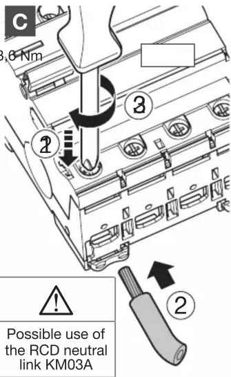
For an RCD where two or three circuits are to be protected, the Hager neutral link KM03A may be connected to the outgoing N terminal for the convenient splitting of the neutrals.
Electrical connection for P+N or for three phase only.
Three phase & neutral use or Three phase use

Single phase use
Two circuits

One circuit

Position contact indication.

Earth leakage fault indication.

Single phase connection.

Three phase connection.

A

B

C


Auxiliary possibilities.
MZ201
MZ202
MZ203
MZ204
MZ205
MZ206

Locking device for handle MZN175.


Protection against dust
In case of work activities nearby, make sure that the electrical installation is protected against dust if the enclosure is not IP5x.


Prekės ženklas : HAGER
Modelis : CEA663T
Kategorija : Automatinis Jungiklis