Bergen 180 247/3591 - Szekrény Heart of House - Ingyenes használati útmutató
Találja meg az eszköz kézikönyvét ingyenesen Bergen 180 247/3591 Heart of House PDF formátumban.

Felhasználói kérdések a következőről Bergen 180 247/3591 Heart of House
0 kérdés erről a készülékről. Válaszolj azokra, amiket ismersz, vagy tedd fel a sajátod.
Tegyél fel egy új kérdést erről a készülékről
Töltse le az útmutatót a következőhöz Szekrény PDF formátumban ingyenesen! Találja meg kézikönyvét Bergen 180 247/3591 - Heart of House és vegye vissza elektronikus eszközét a kezébe. Ezen az oldalon közzé van téve az eszköze használatához szükséges összes dokumentum. Bergen 180 247/3591 márka Heart of House.
HASZNÁLATI ÚTMUTATÓ Bergen 180 247/3591 Heart of House
Bergen 180 foil/Mirror doors
Assembly Instructions Please keep for future reference
248/3591
248/8015
Foil/Mirror doors

Dimensions
Width - 180cm
Depth - 6.7cm
Height-195.2cm
Tip : To prevent damage, we recommend that you build your unit on the carton(s) it was packed in
248/8015 WALFOIL MIRROR
248/3591 OAK FOIL MIRROR
Important – Please read these instructions fully before starting assembly
If you need help or have damaged or missing parts, call the Customer Helpline:
Argos = 0345 6400800

Safety and Care Advice
Important – Please read these instructions fully before starting assembly
- Check you have all the components and tools listed on pages 2 and 3.
- Remove all fittings from the plastic bags and separate them into their groups.
-
Keep children and animals away from the work area, small parts could choke if swallowed.
• Make sure you have enough space to layout the parts before starting. -
Do not stand or put weight on the product, this could cause damage.
- Assemble the item as close to its final position (in the same room) as possible.
• Assemble on a soft level surface to avoid damaging the unit or your floor. - Parts of the assembly will be easier with 2 people.
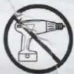
•To reduce the likelihood of damaging your product please ensure that your
power drill is set on a low torque setting.
- Dispose of all packaging carefully and responsibly.
Care and maintenance
- Only clean using a damp cloth and mild detergent, do no use bleach or abrasive cleaners.
- From time to time check that there are no loose screws on this unit.
• This product should not be discarded with household waste. Take to your local authority waste disposal centre.
Handy Hints
- Assemble all parts and bolts loosely during assembly, only once the product is complete should you fully tighten the bolts
• Regularly check and ensure that all bolts and fittings are tightend properly.
Note: if required the next page can be cut out and used as reference throughout the assembly. Keep this page with these instructions for future reference.
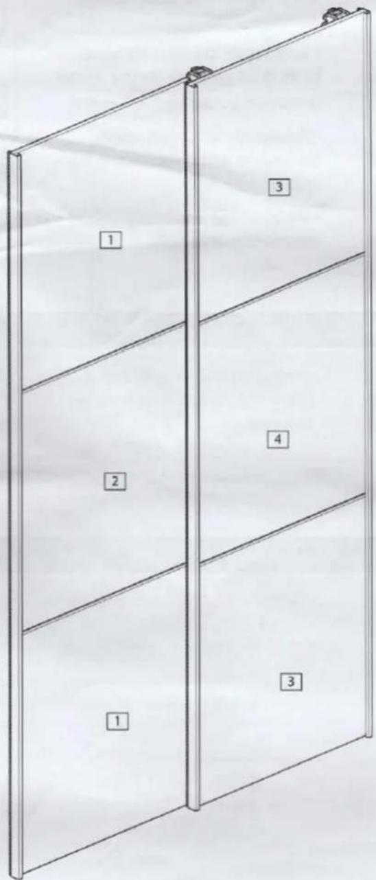
Components - Panels
If you have damaged or missing parts, call the
Customer Helpline:03456 400 800
Please check you have all the panels listed below
natural_image
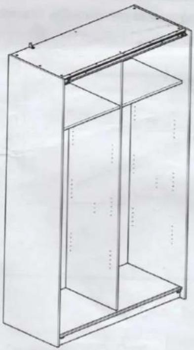
Technical line drawing of a rectangular metal enclosure with internal compartments (no text or symbols)Cabinet supplied separately
249/4834
248/6921
226/8730

natural_image
Blank white image with faint horizontal lines and small dots at top corners (no text or symbols)1 Segment x2 (91.5 x 65cm) P3334
natural_image
Blank white image with faint smudges and no visible text, symbols, or discernible objects.3 Segment x2 (91.5 x 65cm) PS3335

natural_image
Blank white image with no visible content, text, or symbols2 Segment middle x1 (91.5 x 65.1cm) P3270

natural_image
Blank white image with no visible content, text, or symbols4 Segment middle x1 (91.5 x 65.1cm) PS3274
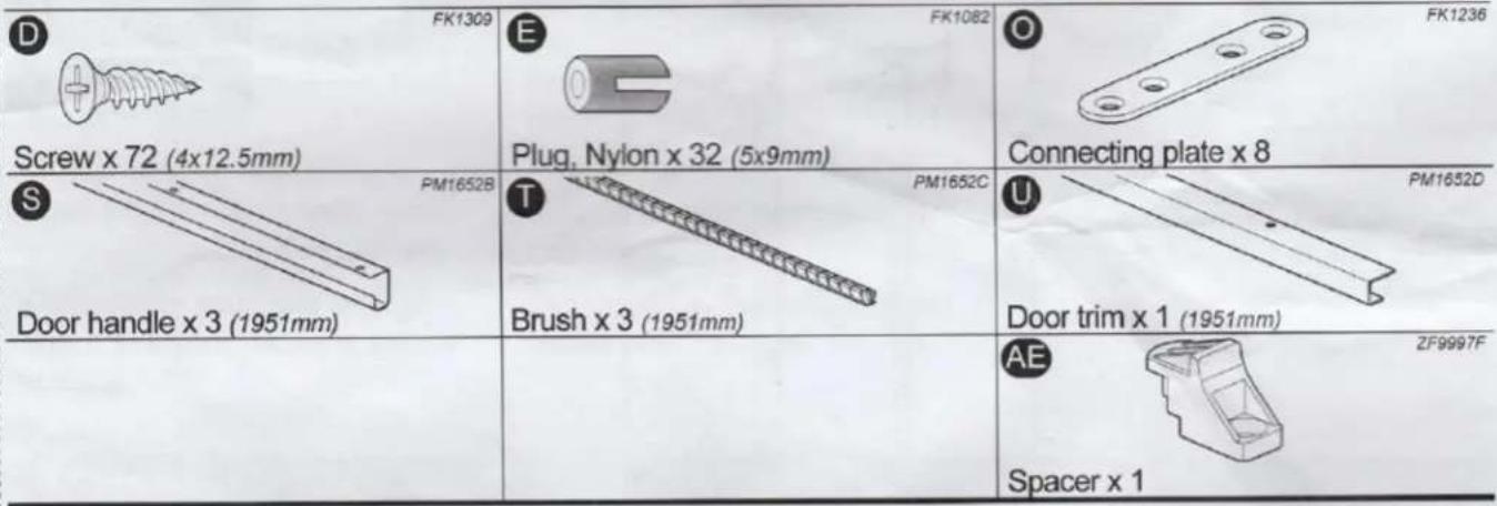
Components - Fittings
Please check you have all the fittings listed below
Note: The quantities below are the correct amount to complete the assembly. In some cases more fittings may be supplied than are required.

natural_image
Blank white image with no visible content, text, or symbols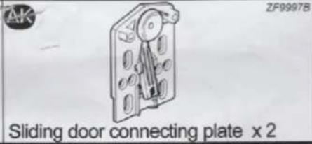

Tools required

Phillips screwdriver (medium & large)


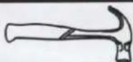
Small hammer
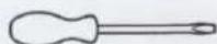
Flatblade screwdriver
(medium)
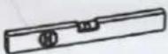
Spirit level
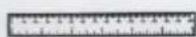
Ruler/tape measure
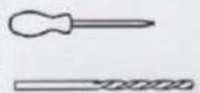
Piercer
(small)
5mm Suitable drill bit
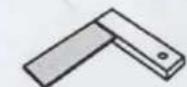
Setsquare
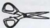
Scissors
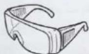
Eye protection (when using a hammer or drill)
Ruler - Use this ruler to help correctly identify the screws

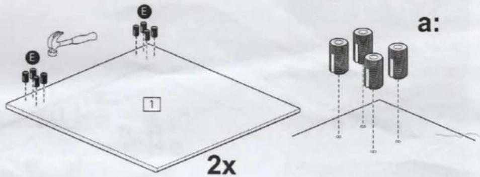
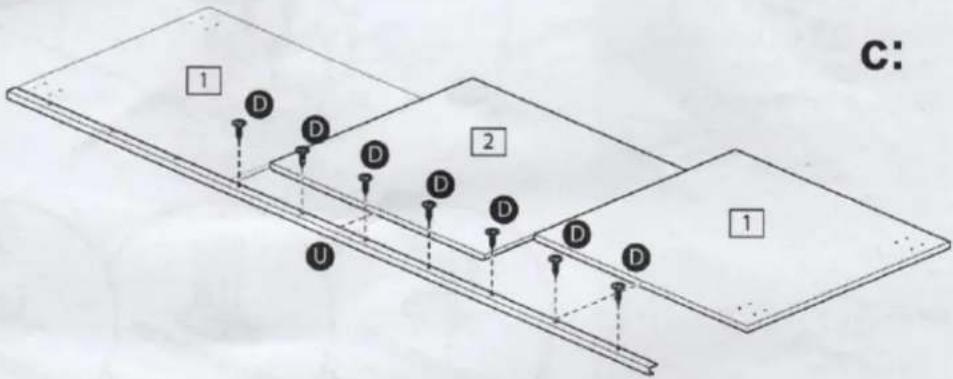
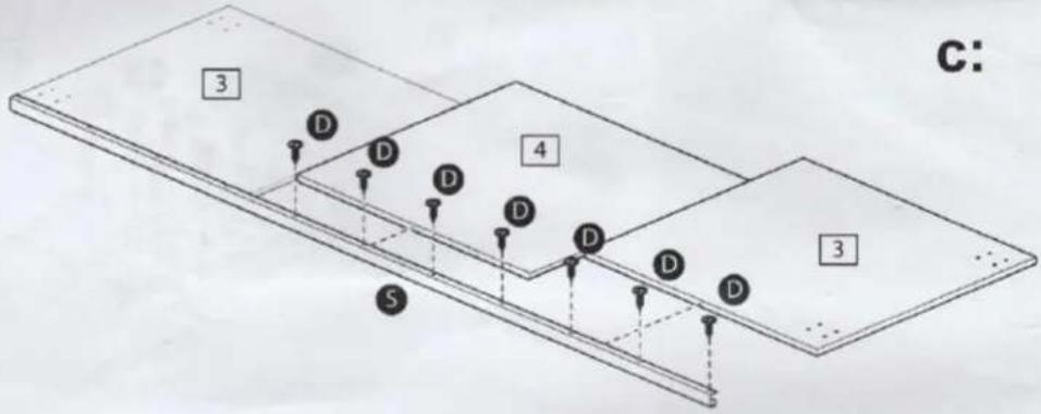
Assembly Instructions
Step 2
3 Segment slide door left
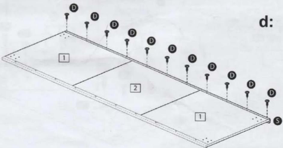
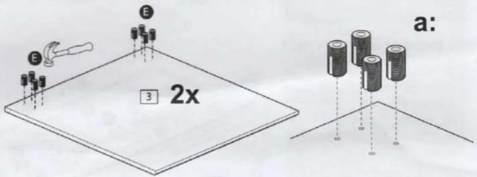
a: Put 8x nylon plug into the segment 1. Use a small hammer. Repeat this step.
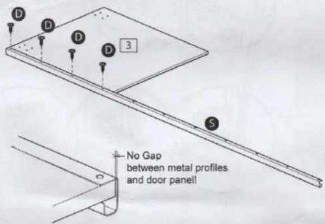
b: Mount door trim Ⓗ with 3x screws Ⓓ on segment 1
Note: there should be no gap between doorsegment 1 and door trim U.

b:
C: Mount segment middle 2 with 3x screws D on door trim U. Mount segment 1 with 4x screws D on door trim U.
d: Mount door handle S on segment 1 with 4x screws D and on middle segment 2 with 3x screws D.
Note: there should be no gap between doorsegment 1 and door handle 5.
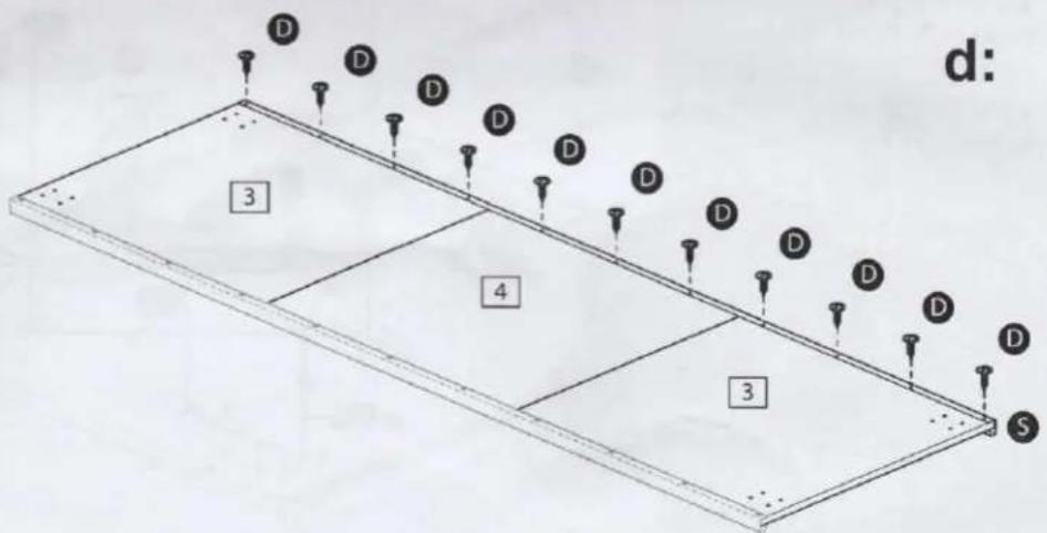
Assembly Instructions
Step 2
3 Segment slide door left
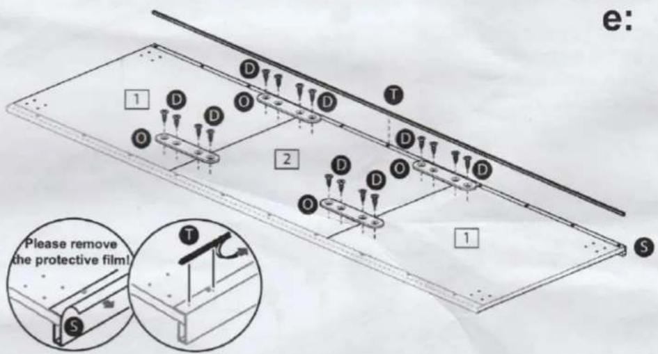
e: Mount 4x connecting plate O, each with 2x screws D on segment 1 and 2x screws D on middle segment 2.
Remove protective film from door handle S. Stick 1x brush T onto door handle S by partially removing the cover from adhease as brush is applied.
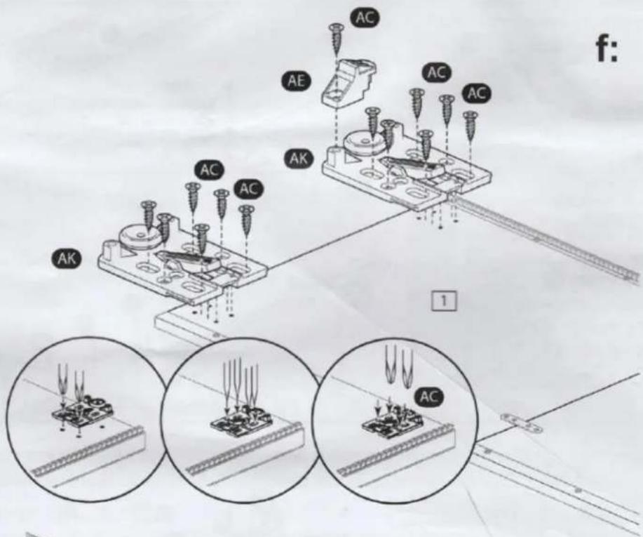
f: Upside.
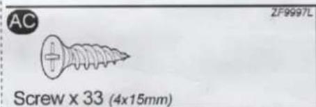
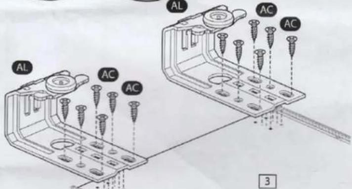
Mount 2x Sliding door connecting plate AK squarely by using the guidemarks in the plate AK, each with 6x screws AC on segment 1. Attach 1x spacer AE with 1x screw AC on the brush side sliding door connecting plate AK.
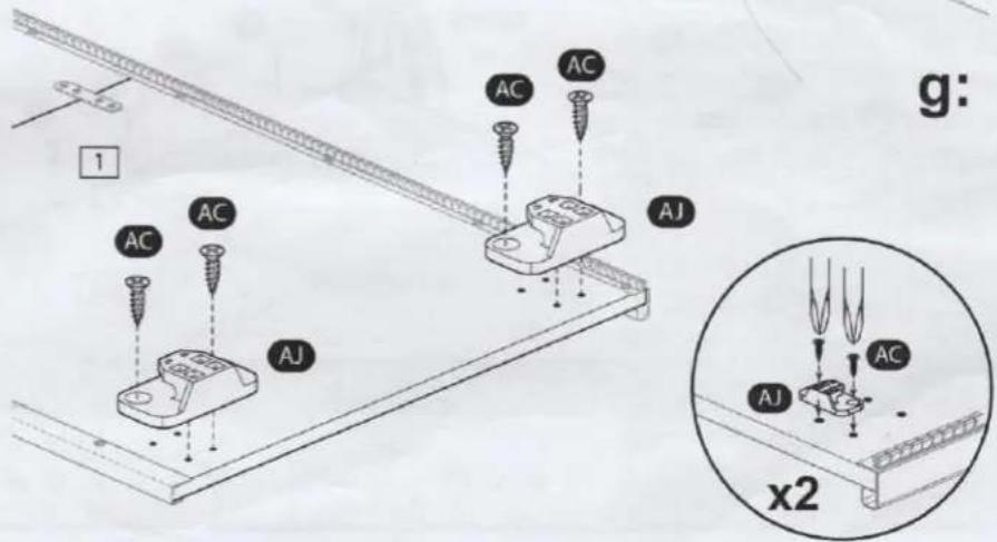
g: Underside.
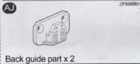
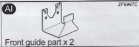
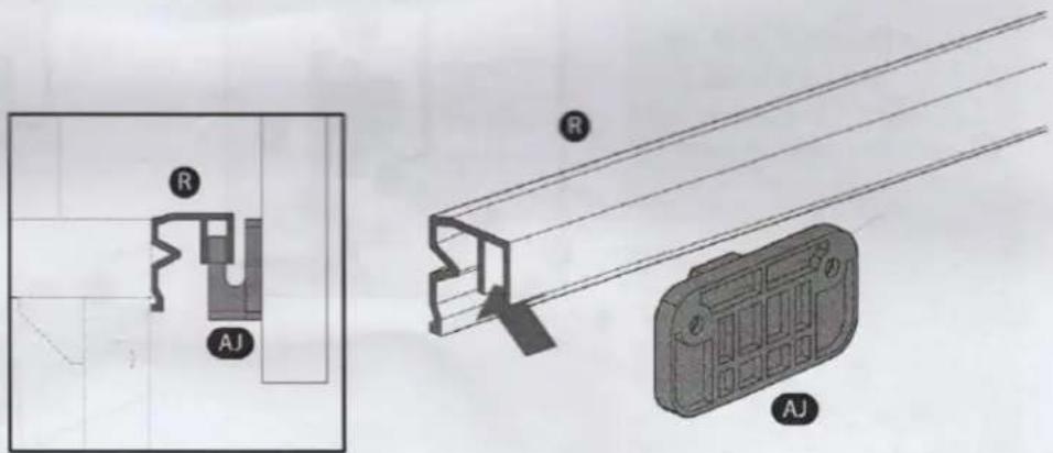
Mount 2x back guide part AJ, each with 2x screws AC on segment 1.
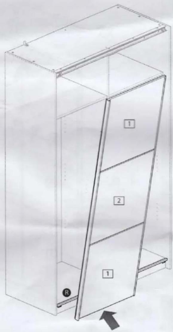
Assembly Instructions
Step 3
Place left slide door
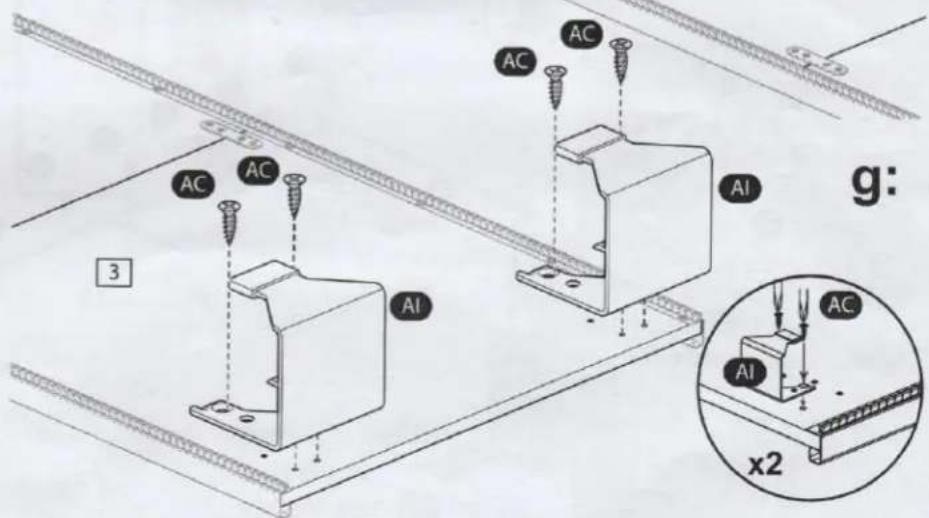
2 People are required for step 3a and 3b.
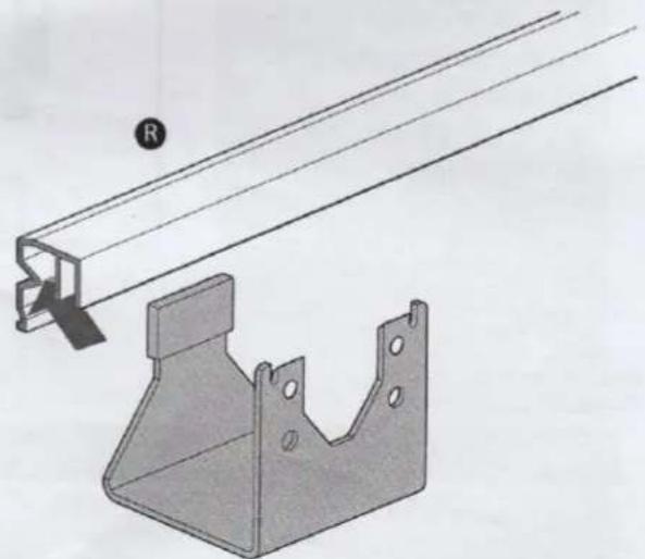
a: Hook the 2x back guide part AJ into the plastic guide rail R.
a:Detail.
The hook of the back guide part AJ should be in the front guide of the plastic guide rail R
natural_image
Technical line drawing of a cabinet with three drawers and an open door, showing internal structure (no text or symbols)a:
Assembly Instructions
Step 3
Place left slide door
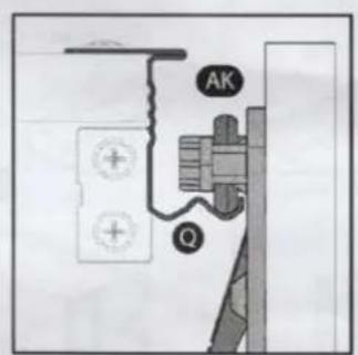
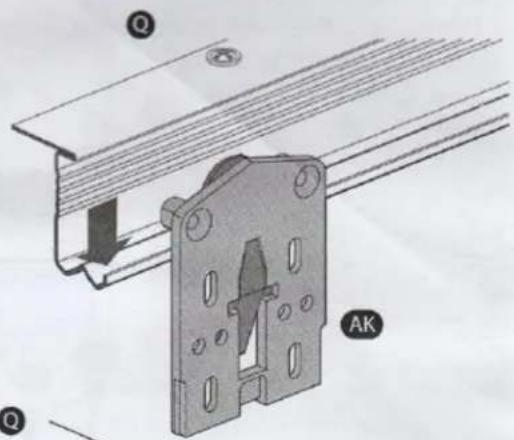
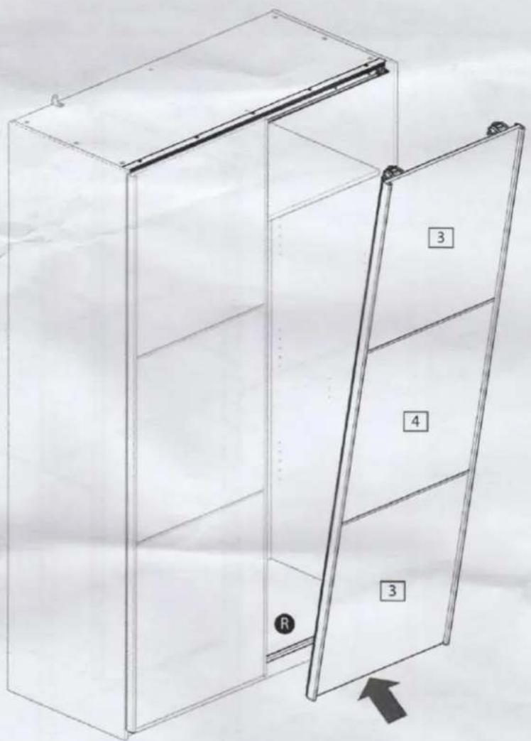
b: Hook Sliding door connecting plate AK on metal guide rail Q.
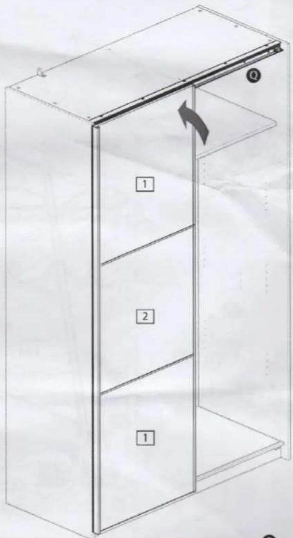
b:
b: Detail.
The wheel of the sliding door connecting plate AK should be in the front guide of the metal guide rail Q.
To lock the door, lock the Sliding door connecting plate AK on the guide rail with the locking pawl.
Assembly Instructions
Step 4
3 Segment slide door right
a: Put 8x nylon plug into the segment 3. Use a small hammer. Repeat this step.
b: Mount door handle ⑤ with 4x screws D on segment ③.
Note: there should be no gap between doorsegment 3 and door handle 5.
C: Mount segment middle 4 with 3x screws D on door handle S. Mount segment 3 with 4x screws D on door handle S.
d: Mount door handle S on segment 3 with 4x screws D and on middle segment 4 with 3x screws D.
Note: there should be no gap between doorsegment 3 and door handle 5.
b:
Assembly Instructions
Step 4
3 Segment slide door right
e: Mount 4x connecting plate O, each with 2x screws D on segment 3 and 2x screws D on middle segment 4.
Remove protective film from door handle Ⓙ. Stick 2x brush Ⓣ onto 2x door handle Ⓗ by partially remove the cover from adhease as brush is applied.
f: Upside.
Mount 2x sliding door connecting bracket AL squarely by using the guidemarks in the plate AL, each with 6x screws AC on segment 3.
g: Underside.
Mount 2x front guide part AI, each with 2x screws AC on segment 3
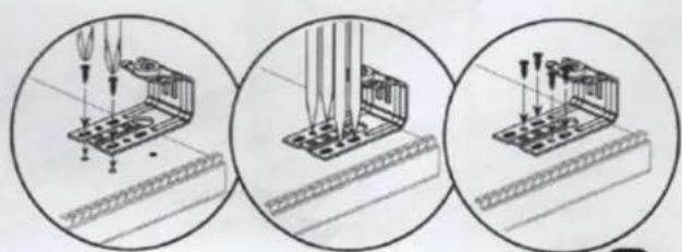
natural_image
Three circular diagrams showing mechanical assembly steps: top view with tool, middle view with test tubes and clamps, bottom view with base plate (no text or symbols)f:
Assembly Instructions
Step 5
Place right slide door
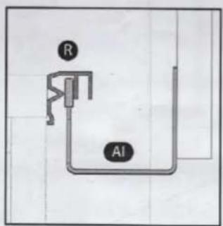
a: Hook the 2x front guide part AI into the plastic guide rail R.
a:
a:Detail.
The hook of the front guide part AI should be in the front guide of the plastic guide rail R
natural_image
Technical illustration of a metal bracket and support structure (no text or symbols)Assembly Instructions
Step 5
Place right slide door
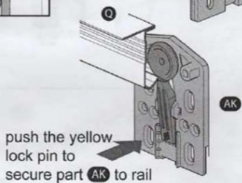
b: Hook the sliding door connecting bracket AL on metal guide rail Q.
b: Detail.
The wheel of the sliding door connecting bracket AL should be in the front guide of the metal guide rail Q.
To lock the door, lock the sliding door connecting bracket AL on the guide rail Q with the locking pawl.
