WL-176 - Router SITECOM - Ingyenes használati útmutató
Találja meg az eszköz kézikönyvét ingyenesen WL-176 SITECOM PDF formátumban.

Felhasználói kérdések a következőről WL-176 SITECOM
0 kérdés erről a készülékről. Válaszolj azokra, amiket ismersz, vagy tedd fel a sajátod.
Tegyél fel egy új kérdést erről a készülékről
Töltse le az útmutatót a következőhöz Router PDF formátumban ingyenesen! Találja meg kézikönyvét WL-176 - SITECOM és vegye vissza elektronikus eszközét a kezébe. Ezen az oldalon közzé van téve az eszköze használatához szükséges összes dokumentum. WL-176 márka SITECOM.
HASZNÁLATI ÚTMUTATÓ WL-176 SITECOM
SITECOM
Wi r el ess Networ k Stor ag e Ruo ter 54g Tur b o
WL-1 7 6
Full manual
1. Table of Contents
1. TABLE OF CONTENTS ...... 2
2. INTRODUCTION .... 4
2.1THANK YOU....4
2.2 FEATURES ....4
2.3 MINIMUM REQUIREMENTS ....5
2.4 PACK AGE CONTENT ....5
3. HARDWARE INSTALLATION ...... 6
3.1 PANEL LAY OUT....6
3.1.1 Top panel 6
3.1.2 Rear Panel....7
3.2 PROCEDURE FOR HARDWARE INSTALLATION....8
3.2.1 Decide where to place your Wireless Broadband Router 8
3.2.2 Setup LAN connection 8
3.2.3 Setup WAN connection 9
3.2.4 Power on 9
4 NETWORK SETTINGS AND SOFTWARE INSTALLATION.... 10
4.1 MAK ETHE CORRECT NETWORK SETTINGS FOR Y OURPC....1 0
5 CONFIGURING WIRELESS BROADBAND ROUTER 12
5.1 START-UP AND LOG IN....1 2
5.2 START-UP AND LOG IN....13
5.2.1 LAN Settings....14
5.2.2 Device Status....16
5.2.3 Internet Status....17
5.2.4 DHCP Client status....18
5.2.5 System Log ....19
5.2.6 Statistic....20
6 RUN SETUP WIZARD 21
7 WIRELESS SETTINGS 23
7.1 WIRELESS BASIC SETTINGS....23
7.2 ADVANCED WIRELESS SETTINGS 25
7.3 WIRELESS SECURITY OPTIONS....27
7.3.1 WEP Encryption....27
7.3.2 802.1x only....29
7.3.3 WPA Pre-shared key 30
7.3.4 WPA Radius 32
7.4 ACCESS CONTROL....33
8 FIREWALL SETTINGS 34
8.1 DMZ 34
8.2 DoS ATTACK 36
8.3 ACCESS CONTROL....37
8.4 URL BLOCK....39
9 ADVANCED SETTINGS 40
9.1 PORT FORWARDING....40
9.2 VIRTUAL SERVER....42
9.3 SPECIAL APPLICATIONS 44
9.4 ALG SETTINGS....46
9.5 UPNP SETTINGS 47
9.6 QoSA....48
9.7 PRINT SERVER....51
10 NAS SYSTEM 53
10.1 GENERAL SETTINGS....53
10.2 SHARE....55
10.2.1 Add Shares....56
10.2.2 Select Share Path....57
10.3 ADVANCED....58
10.4 NAS TOOLS....60
10.4.1 Add Partitions ....61
10.5 NAS STATUS 63
11 TOOLBOX 64
11.1 TIMEZ ONE....65
11.2 REMOTE MANAGEMENT 66
11.3 FIRMWARE UPGRADE....68
11.4 BACKUP SETTINGS....69
11.5 RESET (RESTART) THE ROUTER....70
11.6 DDNSA....71
APPENDIX A 72
GLOSSARY 73
2. Introduction
2.1 Thank you
Thank you for buying the Sitecom Wireless Network Storage Router 54g Turbo WL-176. This Wireless Storage Router is a cost-effective IP Sharing Router that enables multiple users to share the Internet through an ADSL or cable modem. Simply configure your Internet connection settings in the Wireless Broadband Router and connect your PC to the LAN port and you're ready to share files and access the Internet.
The Wireless Storage Router is embedded with a IEEE 802.11g/b access point that allows you to build up a wireless LAN. Besides, it also provides two USB ports which let you easily share the USB storage device and printer. The Wireless Storage Router provides a complete solution for the Small and Medium-sized Business (SMB) and the Small Office/Home Office (SOHO) markets, giving you an instant network today, and the flexibility to handle tomorrow's expanding speed.
2.2 Fe atur e s
• High Internet Access throughput (50M)
- Allow multiple users to share a single Internet line
• Supports up to 253 users
- Provides two USB port for connecting with USB printer or USB mass storage devices
• Internet Access via Cable or xDSL modem
- Allow you to share your files via FTP or Network Neighborhood
• Access Private LAN Servers from the Public Network
• Equipped with four LAN ports (10/100M) and one WAN port (10/100M)
• Provides IEEE 802.11g/b wireless LAN access point
• Support DHCP (Server/Client) for easy setup
- Support advanced features such as: Special Applications, DMZ, Virtual Servers, Access Control, Firewall.
- Allows you to monitor the routers status such as: DHCP Client Log, System Log, Security Log and Device/Connection Status
- Easy to use Web-based GUI for configuration and management purposes
- Remote Management allows configuration and upgrades from a remote site (over the In ternet)
2.3 Mi ni mum Re qui r e ment s
• One External xDSL (ADSL) or Cable modem with an Ethernet port (RJ-45)
• Network Interface Card (NIC) for each Personal Computer (PC)
• PCs with a Web-Browser (Internet Explorer 5.0 or higher, or Netscape Navigator 7.2 or higher)
2.4 Package Content
• One 4-port Wireless Broadband router unit
• One Quick Installation Guide
• On e User Man u al CD
• On e Power Adapter
• CAT-5 UTP Fast Ether n et Cab le
Note:
The WAN "idle timeout" auto-disconnect function may not work due to abnormal activities of some network application software, computer virus or hacker attacks from the Internet. For example, some software sends network packets to the Internet in the background, even when you are not using the Internet. So please turn off your computer when you are not using it. This function also may not work with some ISP. So please make sure this function can work properly when you use this function in the first time, especially your ISP charge you by time used.
3. P PHardware Installation
3.1 Pane I L ay o ut
3.1.1 Top panel

| LED | Function | Color | Status | Description |
| POWER | Power indication | Green | On | Power is being applied to this product. |
| Li n k/Modem | Li n k Statu s | Gre en | On | The c or r espon di ng WAN or LAN p or t is li n ked. |
| Bli n ki | The c or r espon di ng WAN or LAN p or t is ng sen di ng or r ec ei vi ng data. | |||
| WLAN | Wireless Activity | Gre en | On | Wireless LAN had been enabled |
| Blinking | Sending or receiving data via wireless. | |||
| 1 0 0 Mbps | s Data Rate | Gre en | Bli n ki | The c or r espon di ng WAN or LAN p or t is ng sen di ng or r ec ei vi ng data. |
| On | Data is transmitting in 100Mbps on the c or r esp on di ng LAN p or t. | |||
| USB1/2 | USB Device | Green | On | The USB Device is connected. |
3.1.2 Rear Panel
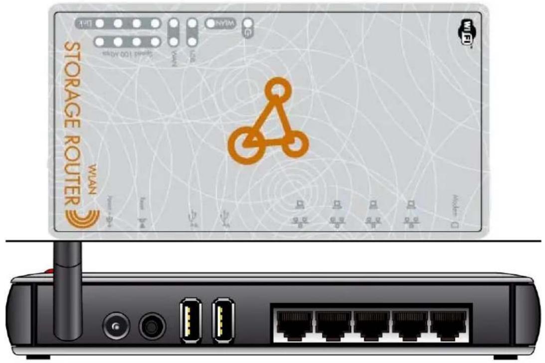
Port Description
POWER Power inlet
Modem The port where you will connect your cable (or DSL) modem or Ether n et r outer.
Port 1-4 The ports where you will connect networked computers and other devices.
To reset system settings to factory defaults, press the reset button for at least 4 sec on ds.
Reset
To reboot the device, press the reset button less than 4 sec on ds.
US B 1 -2
The ports where you will connect USB devices such as USB mass stor ag e devi c e and d p r in ter .
Note:
Please connect you USB mass storage device to the external power supply before you can next it to the router.
Note:
Please c on n ec t th e USB mass stor ag e dedi c ated to th i s NAS r ou ter i n Ath e better management function. For the USB flash disk that used to share files among different PCs and notebooks, please connect it to USB port 2 for instant setup.
USB port 1 for
3.2 Procedure for Hardware Installation
3.2.1 Decide where to place your Wireless Broadband Router
You can place your Wireless Broadband Router on a desk or other flat surface, or you can mount it on a wall. For optimal performance, place your Wireless Broadband Router in the center of your office (or your home) in a location that is away from any potential source of interference, such as a metal wall or microwave oven. This location must be close to power and network c on n ect i on .
3.2.2 Set up LAN connection
- Wired LAN connection: connects an Ethernet cable from your computer's Ethernet port to one of the LAN ports of this product.
- Wireless LAN connection: locate this product at a proper position to gain the best tran smi t per f or man c e.
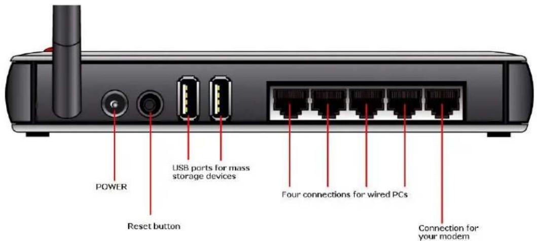
Figure 2-3 Setup of LAN and WAN connections for this product.
3.2.3 Setup WPAN connection
Prepare an Ethernet cable for connecting this product to your cable/xDSL modem or Ethernet backbone. Figure 2-3 illustrates the WAN connection.
3.2.4 Power on
Connecting the power cord to power inlet and turning the power switch on, this product will automatically enter the self-test phase. When it is in the self-test phase, the Power LED will not be lighted for about 15 seconds, and then Power will flash 9 times to indicate that the self-test operation has finished. Finally, power will be lit continuously to indicate that this product is in normal operation.
4 Network Settings and Software Installation
To use this product correctly, you have to properly configure the network settings of your computers and install the attached setup program into your MS Windows platform (Windows 20 0 0 / X P).
4.1 Make The Correct Network Settings for your PC
The default IP address of this product is 192.168.0.1, and the default subnet mask is 255.255.255.0. These addresses can be changed on your need, but the default values are used in this manual. If the TCP/IP environment of your computer has not yet been configured, you can refer to Appendix A to configure it. For example,
- configure IP as 192.168.0.100, subnet mask as 255.255.255.0 and gateway as 192.168.0.1, or more easier,
- configure your computers to load TCP/IP setting automatically, that is, via DHCP server of this product.
After installing the TCP/IP communication protocol, you can use the ping command to check if your computer has successfully connected to this product. The following example shows the ping procedure for Windows 95 platforms. First, execute the ping command
pin g 1 9 2.1 68 .0 . 1
If the following messages appear:
Pinging 192.168.0.1 with 32 bytes of data:
Reply from 192.168.0.1: bytes=32 time=2ms TTL=64
a communication link between your computer and this product has been successfully established. Otherwise, if you get the following messages,
Pinging 192.168.0.1 with 32 bytes of data:
Request timed out.
There must be something wrong in your installation procedure. You have to check the following items in sequence:
- Is the Ethernet cable correctly connected between this product and your computer?
Tip: The LAN LED of this product and the link LED of network card on your computer must be lighted.
- Is the TCP/IP environment of your computers properly configured?
Please check www.sitecom.com for up to date drivers & utilities, manuals and support
Tip: If the IP address of this product is 192.1 68.0 .1, the IP address of your computer be 192.1 68.0 .X and default gateway must be 192.1 68.0 .1.
5 Configuring Wireless Broadband Routen
This product provides Web based configuration scheme, that is, configuring by your Web browser, such as Netscape Communicator or Internet Explorer. This approach can be adopted in any MS Windows, Macintosh or UNIX based platforms.
Wireless LAN
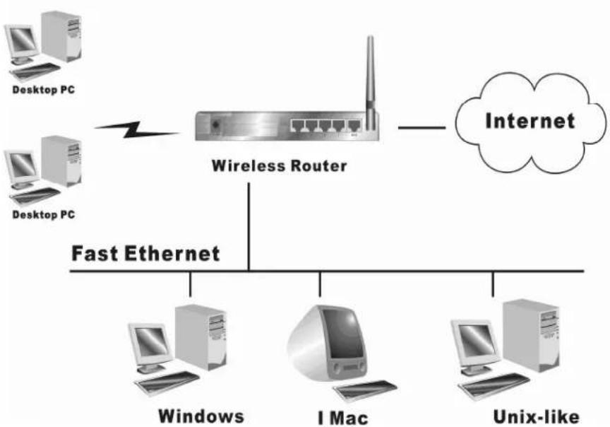
flowchart
graph TD
    A["Desktop PC"] --> B["Wireless Router"]
    C["Desktop PC"] --> B
    B --> D["Internet"]
    E["Windows"] --> F["Fast Ethernet"]
    G["I Mac"] --> H["Fast Ethernet"]
    I["Unix-like"] --> J["Fast Ethernet"]
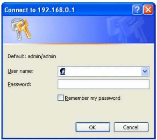
5.1 Start-up and Log in
Activate your browser, and disable the proxy or add the IP address of this product into the exceptions. Then, type this product's IP address in the Location (for Netscape) or Address (for IE) field and press ENTER. For example: http://192.168.0.1.
After the connection is established, you will see the web user interface of this product. There are two appearances of web user interface: for general users and for system administrator.
To log in as an administrator, enter your login name and password (default: admin/admin) and click OK. If the password is correct, the web appearance will be changed into administrator configure mode. As listed in its main menu, there are several options for system administration.
Note:
The default IP-address for this router is: 192.168.0.1
5.2 S t ar t -up and L o g in
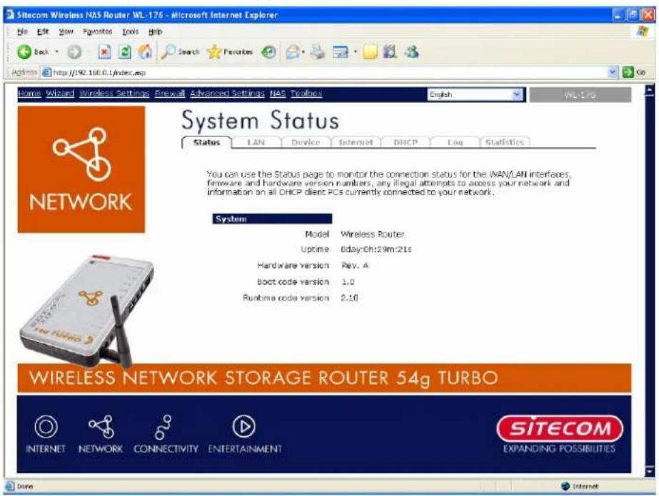
The Status section allows you to monitor the current status of your router. You can use the
Status page to monitor: the connection status of the Broadband router's WAN/LAN in the current firmware and hardware version numbers, any illegal attempts to access your network, and information on all DHCP client PCs currently connected to your network.
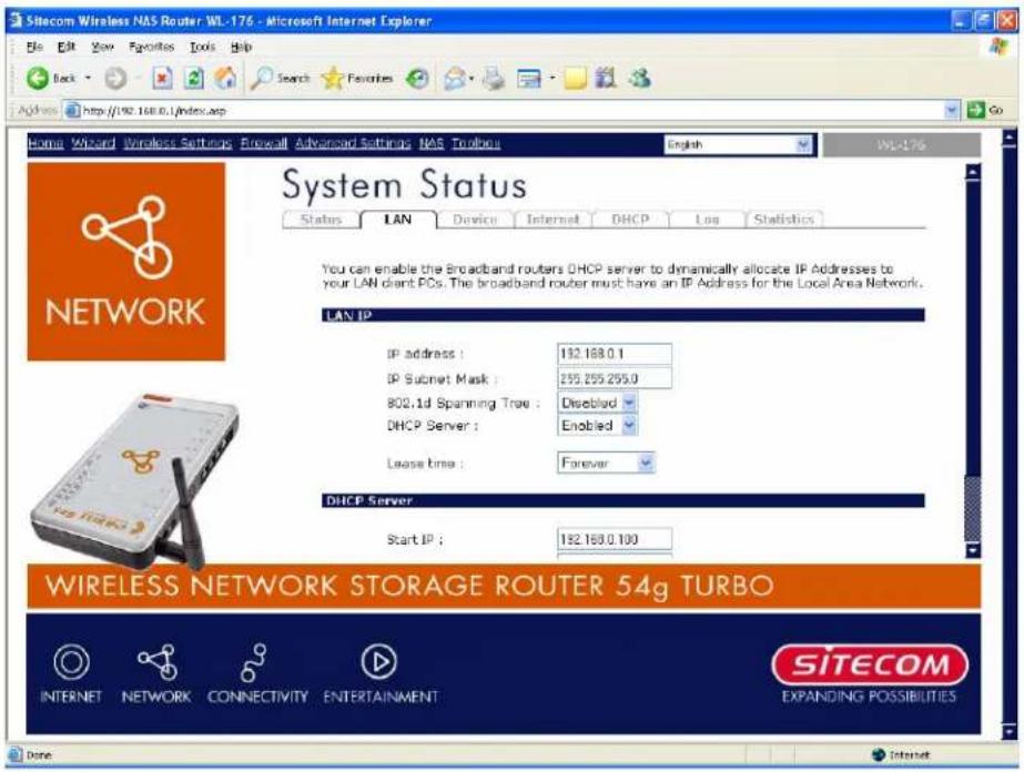
5.2.1 LAN Settings
The LAN Port screen below allows you to specify a private IP address for your router's LAN ports as well as a subnet mask for your LAN segment.
| Parameters | Default | Description |
| IP address | 192.168.0.1 | This is the router's LAN port IP address (Your LAN c lien ts def au lt g ateway IP addr ess) |
| IP Subnet Mask | 255.255.255.0 | Specify a Subnet Mask for your LAN segment |
| 802.1d Spanning Tree | Disabled | If 802.1d Spanning Tree function is enabled, this router will use the spanning tree protocol to p r even t n etw or k loop s. |
| DHCP Server | Enabled | You can enable or disable the DHCP server. By Enabling DHCP server the router will automatically give your LAN clients an IPaddr ess. A |
| Lease Time | Forever | The DHCP when enabled will temporarily give your LAN clients an IP address. In the Lease Time setting you can specify the time period that the DHCP lends an IP address to your LAN clients.The DHCP will change your LAN client's IP address when this time threshold period is r eac h ed A |
| IP Address Pool | You can select a particular IP address range for your DHCP server to issu e IP addr esses to y ou r LAN CI ien ts. ANote: By default the IP range is from: Start IP 192.168.0.100 to End IP 192.168.0.199. If you want your PC to have a static/fixed IP address then you'll have to choose an IP address outside this IP address Pool | |
| Domain Name | You can specify a Domain Name for your LAN | |
Click
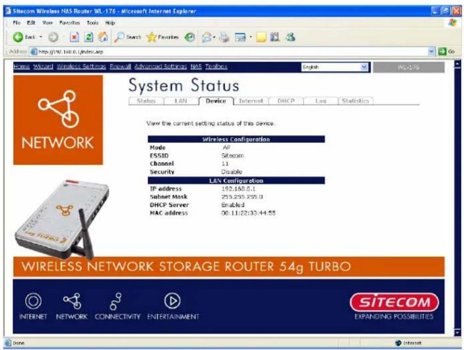
5.2.2 Device Status
View the Broadband router's current configuration settings. The Device Status configuration settings you've configured in the Wizard / Basic Settings / Wireless Settings section.
| Parameters | Description |
| Device Status | This page displays the Broadband router LAN port's current LAN IP Address and Subnet Mask. It also shows whether the DHCP Server function is enabled/disabled.. |
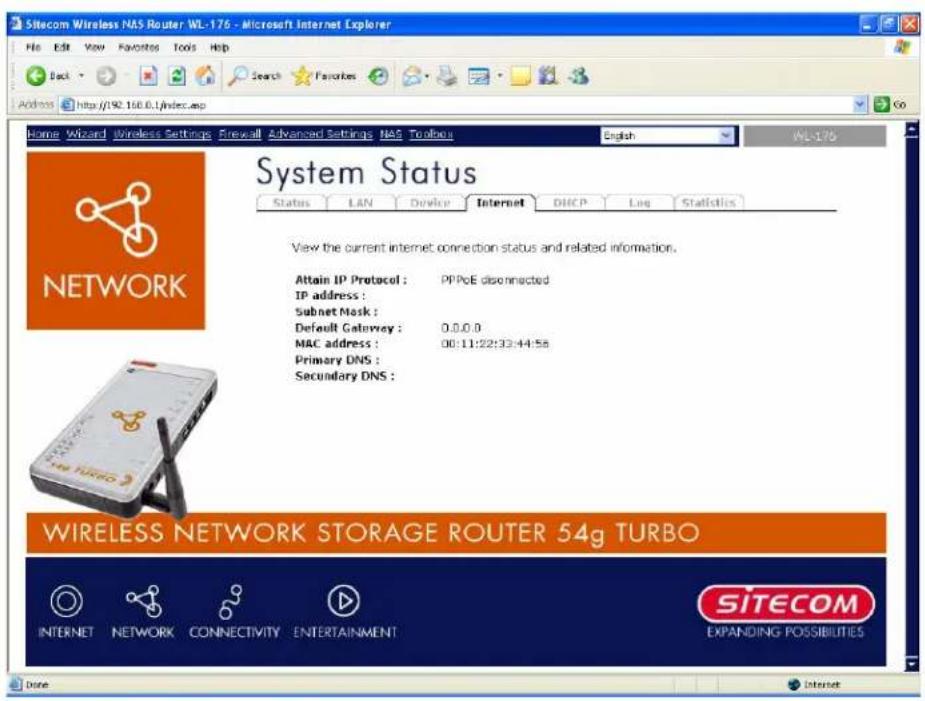
5.2.3 Internet Status
View the Broadband router's current Internet connection status and other related i n f or mati on.
Parameters
Description
In ter n et Con n ec ti on
This page displays whether the WAN port is connected to Cable / DSL connection. It also displays the outer 's WAN or WAN IP address, Subnet Mask, and ISP Gateway as well as the Primary DNS and Secondary DNS being used.
5.2.4 DHCP Client status
View your LAN client's information that is currently linked to the Broadband router's DHCP server.
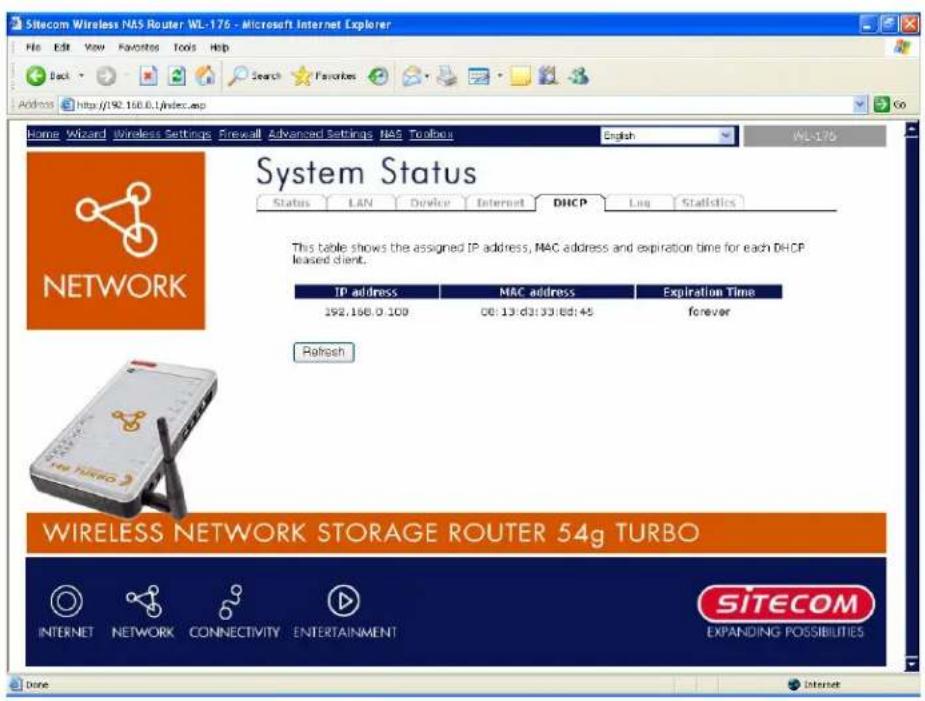
| Parameters | Description |
| Active DHCP Client | This page shows all DHCP clients (LAN PCs) currently connected to you run with k. The “Ac ti ve DHCP client Tab l e” display the address and the MAC address and Ti me Ex p i red of each LAN Client. Use the Refresh button to get the most up dated situation on |
5.2.5 System Log
View the operation Log of the system.
![Sitecom Wireless NAS Router WL-176 - Microsoft Internet Explorer File Edit View Favorites Tools Help Back Search Favorites Address http://92.160.0.1/index.asp Home Wizard Wireless Settings Firewall Advanced Settings NAS Toolbox English WL-176 System Status Status LAN Device Internet DHCP Log Statistics View the system operation information. You can see the system start up time, connection process...etc. here. Jan 1 00:00:00 (none) syslog.info syslogd started: BusyBox v1.00-pre2 (... Jan 1 00:00:06 (none) user.info ushops: ushop server (V0.9.9-pre) start Jan 1 00:00:13 (none) daemon.info pppd[457]: RP-PFPoE plugin version 3. Jan 1 00:00:13 (none) daemon.notice pppd[457]: ppd 2.4.3b1 started by Jan 1 00:00:13 (none) daemon.info pppd[457]: Using interface ppp0 Jan 1 00:00:13 (none) daemon.wora pppd[457]: Couldn't increase MTU to 1 Jan 1 00:00:13 (none) daemon.err pppd[457]: Couldn't increase MBU to 15 Jan 1 00:00:13 (none) daemon.wara pppd[457]: demand.. Jan 1 00:00:13 (none) daemon.notice pppd[457]: local TP address 18.64 Save Clear Refresh WIRELESS NETWORK STORAGE ROUTER 54g TURBO INTERNET NETWORK CONNECTIVITY ENTERTAINMENT SITECOM EXPANDING POSSIBILITIES Done Internet](/content/2026/06/1150173/images/1052c24defe552e9f55bb0e77873342f4a5d6aa205dfddaa1fd6bbec379bf4ae.jpg)
| Parameters | Description |
| System Log | This page shows the current system log of the Broadband router. It disp l ay s an y ev en t oc c u r r ed af ter sy stem start u p . At the b ottom of th e p ag e, th esy stem l og c an be sav edto a local file for further processing or the system log can be clearedor it can be refreshedto g et th e most u p dated si tu ati on . Wh en th esy stem i sp ow er ed down, the system log will disappear if not saved to a local file. |
5.2.6 St at i s t i c
View the statistic of packets sent and received on WAN, LAN and Wi rel ess LAN.
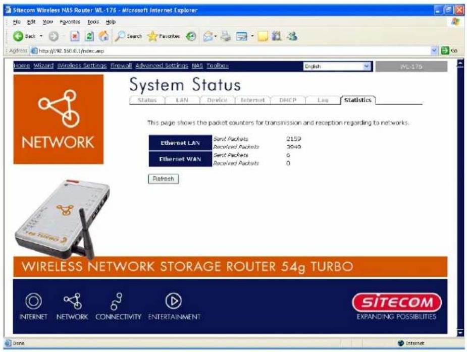
| Par ameter s A | Desc r i p ti on |
| Statistics | Shows the counters of packets sent and received on WAN, LAN and d Wi rel ess LAN. |
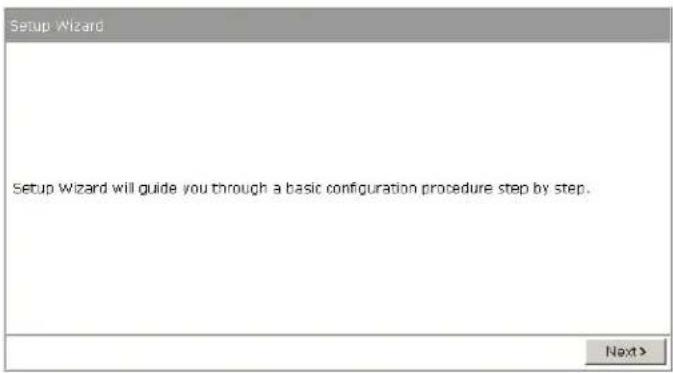
6 Run Set up Wizard
- Click Wizard to configure the router.
- The Setup wizard will now be displayed; check that the modem is connected and click Next.
Setup wizard
- Select your country from the Country list.
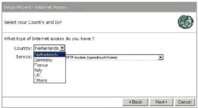
• From Service, select your internet provider. Click Next.
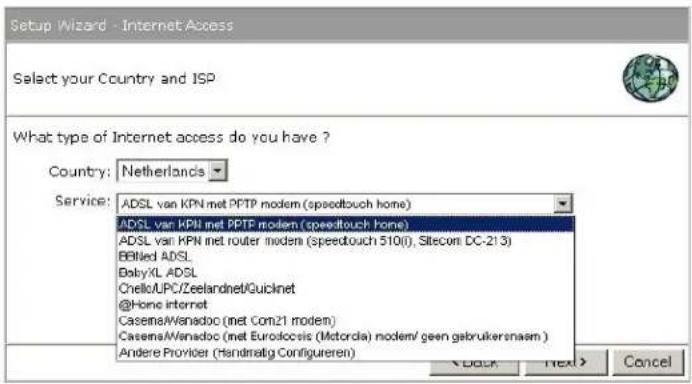
- Depending on the chosen provider, you may need to enter your user name and password, MAC address or hostname in the following window. After you have entered the correct information, click Next.
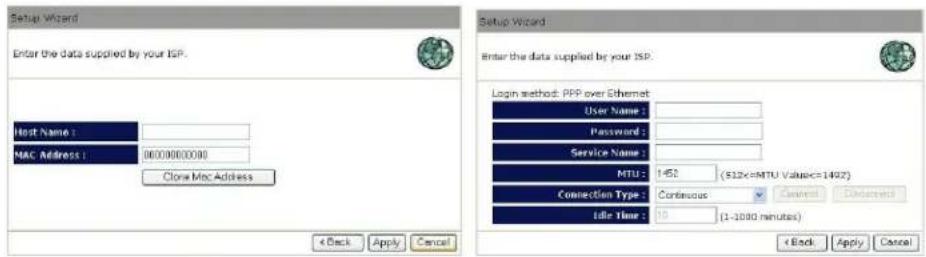
- Click APPLY to complete the configuration.
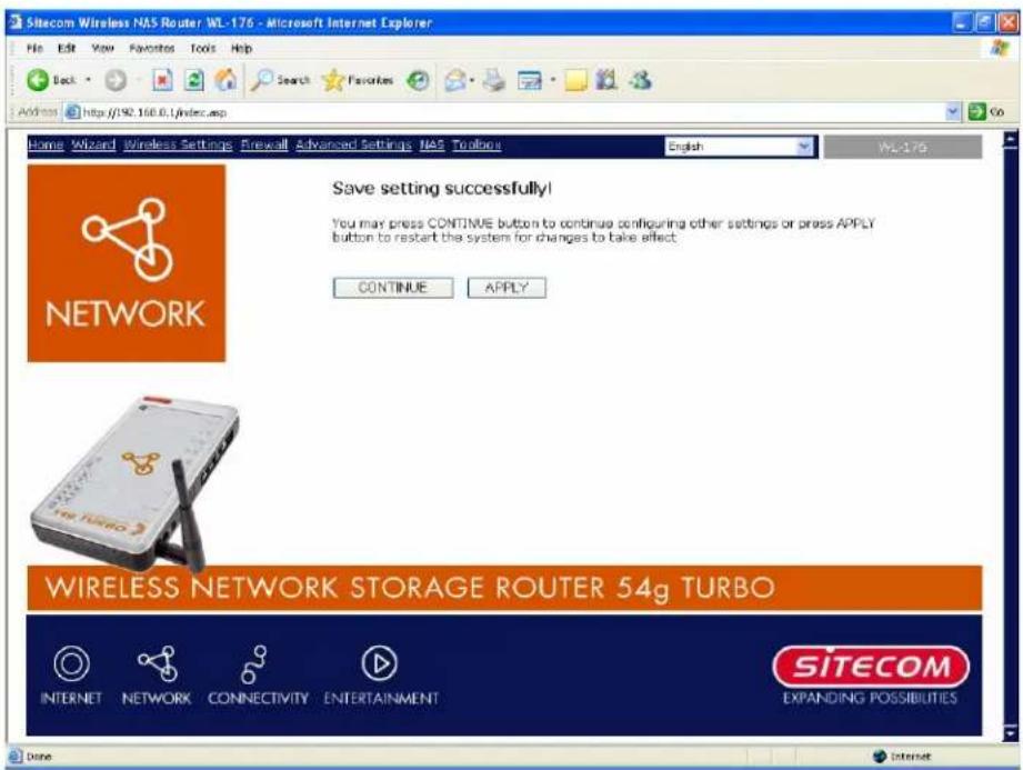
- The router will now save the settings and restart, please wait 60 seconds and you will be transferred back to the status window. The configuration is complete.
- Wait for about 10 seconds to allow the router to connect to the Internet.
7 Wireless Settings
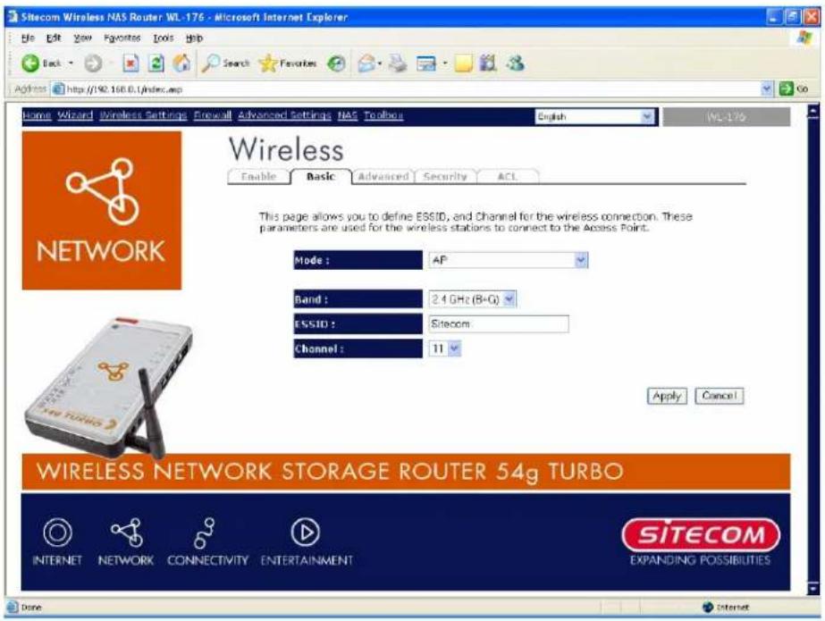
7.1 Wireless Basic Settings
You can set parameters that are used for the wireless stations to connect to this router. The parameters include Mode, ESSID, Channel Number and Associated Client.
| Parameters | Description |
| Mode | It allows you to set the AP to AP, Station, Bridge or WDS mode. |
| Band | It allows you to set the AP fix at 802.11b or 802.11g mode. You also can select B+G mode to allow the AP select 802.11b and 802.11g connection automatically. |
| ESSID | This is the name of the wireless LAN. All the devices in the same wireless LAN should have the same ESSID. Default ESSID for this device is: Sitecom |
| Channel Number | The channel used by the wireless LAN. All devices in the same wireless LAN should use the same channel. |
| WLAN MAC | This is the MAC address used by the Wireless interface of this AP when it is in the station mode. |
| Clone MAC | Click the "Clone MAC" button will copy the MAC address of your PC, that you are using to configure the AP, to the WLAN MAC. |
| MAC address | If you want to bridge more than one networks together with wireless LAN, you have to set this access point to "AP Bridge-Point to Point mode", "AP Bridge-Point to Multi-Point mode" or "AP Bridge-WDS mode". You have to enter the MAC addresses of other access points |
Si tec om Wi r el ess Networ k Stor ag e Router 54g Tur b o WL-1 76
| th at j o i n the b r i d g i n g . A | |
| Set Security | Click the "Set Security" button, then a "WDS Security Settings" will pop up . You can set the sec u r i ty p ar ameter s u sed to b r i d g e ac c ess p o i n tog ether h er e wh en y ou r AP i s i n AP Br i d g e modes. |
7.2 Advanced Wireless Settings
You can set advanced wireless LAN parameters of this router. The parameters include Authentication Type, Fragment Threshold, RTS Threshold, Beacon Interval, Preamble Type. You should not change these parameters unless you know what effect the changes will have on th is r ou ter .
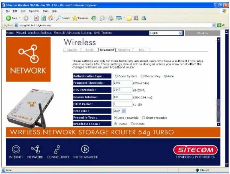
| Parameters | Description |
| Authentication Type | There are two authentication types: "Open System" and "Shared Key". When you select "Open System", wireless stations can associate with this wireless router without WEP encryption. When you select "Shared Key", you should also setup WEP key in the "Encryption" page and wireless stations should use WEP encryption in the authentication phase to associate with this wireless router. If you select "Auto", the wireless client can associate with this wireless router by using any one of these two auth en ti c ati on types. |
| Fragment Threshold | "Fragment Threshold" specifies the maximum size of a packet during the fragmentation of data to be transmitted. If you set this value too low, it will result in bad performance. |
| RTS Threshold | When the packet size is smaller the RTS threshold, the wireless router will not use the RTS/ CTS mec h an ism to send d th i sp ac k et. |
| Beacon Interval | The interval of time that this wireless router broadcast a beacon. Beac on i s u sed to syn c hr on i z e th ewir el ess n etwork . |
| Data Rate | The "Data Rate" is the rate this access point uses to transmit datap ac k ets. ATh e Aac c ess Ap o i n t Aw i l l Au se Ath e Ah i g h est Ap ossi b l e n tr an smi ssi on r ate to tr an smi t th e data p ac k ets. |
| Preamble Type | The “Long Preamble” can provide better wireless LAN compatibility while the “Short Preamble” can provide better wireless LAN per for man c e. |
| Broadcast ESSID | If you enable “Broadcast ESSID”, every wireless station located within the coverage of this access point can discover this access point easily. If you are building a public wireless network, enabling this feature is recommended. Disabling “Broadcast ESSID” can provide better sec u r i ty. |
| IAPP | If you enable “IAPP”, it will allow wireless station roaming between IAPP en ab l ed ac c ess p o i n ts w i th i n th e same wi rel ess LAN. |
| 802.11g Protection | This is also called CTS Protection. It is recommended to enable the protection mechanism. This mechanism can decrease the rate of data collision between 802.11b and 802.11g wireless stations. When the protection mode is enabled, the throughput of the AP will be a little lower due to many of frame traffic should be transmitted. |
Click
7.3 WPireless Security Options
This Access Point provides complete wireless LAN security functions, include WEP, IEEE 802.11x, IEEE 802.11x with WEP, WPA with pre-shared key and WPA with RADIUS. With these security functions, you can prevent your wireless LAN from illegal access. Please make sure your wireless stations use the same security function.
7.3.1 WEP Encryption
When you select 64-bit or 128-bit WEP key, you have to enter WEP keys to encrypt data. You can generate the key by yourself and enter it. You can enter four WEP keys and select one of them as default key. Then the router can receive any packets encrypted by one of the four key s. A
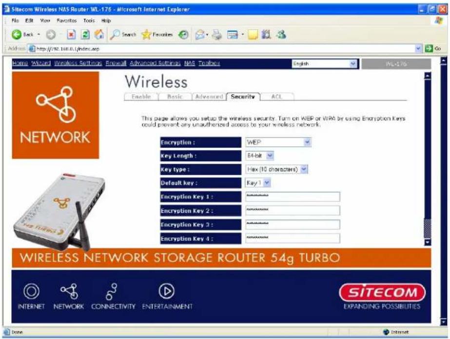
| Parameters | Description |
| Key Length | You can select the WEP key length for encryption, 64-bit or 128-bit. Larger WEP key length will provide higher level of security, but the throughput will be lower. |
| Key Format | You may select to select ASCII Characters (alphanumeric format) or Hexadecimal Digits (in the "A-F", "a-f" and "0-9" range) to be the WEP Key.For example:ASCII Characters:guestHexadecimal Digits:12345abcde |
Si tec om Wi r el ess Network Stor ag e Router 54g Tur b o WL-1 76
Def aultKey ASelect one of the fourth keys to encrypt your data. Only the key you see in the "Def aultkey" will take effect.
Key1 - Key4 The WEP keys are used to encrypt data transmitted in the wireless network.
Fill the text box by following the rules below.
64-bit WEP: input 10-digit Hex values (in the "A-F", "a-f" and "0-9")
r an g e) or 5-di g i t ASCII c h ar ac ter as th e en c r y p ti on k e y s.
128-bit WEP: input 26-digit Hex values (in the "A-F", "a-f" and "0-9")
r an g e) or 1 3-di g i t ASCII c h ar ac ter s as th e en c r y p ti on k e y s.
Click
7.3.2 802.1 x only
IEEE 80 2.1 x i s an au th ent ti c ati on p r otoc ol . Ev er y u ser mu st u se a v al i d ac c o u n t to l A c c ess Poi n t b efor e a c c essi n g t h e w i r e l ess LAN. T h e au th en ti c ati on i s p r oc essed b y server. This mode only authenticates users by IEEE 802.1x, but it does not encrypt the data during comm u nic ati on .
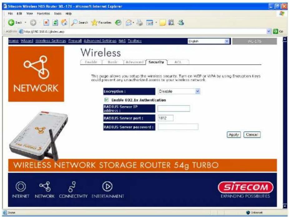
| Par ameter s | Desc r i p ti on |
| RADIUS Server IP address | The IP address of external RADIUS server. |
| RADIUS Server Port | The service port of the external RADIUS server. |
| RADIUS Ser v er Password d | Th e p assw or d u sed b y ex ter n al RADIUS ser v er . |
Click
7.3.3 WPPAPre-shared key
Wi -Fi Protec ted Acc ess (WPA) i s an adv an c ed sec u r i ty stan dar d. You can u se a p r e-sh a k ey to au th ent ti cate wi r el ess stati on s and en c r y p t data du r ing comm u n i c at i on . It u s CCMP(AES) to change the encryption key frequently. So the encryption key is not easy to be b roken by h ack e rs. This s can i m p r o v e sec u r i ty v er y much .
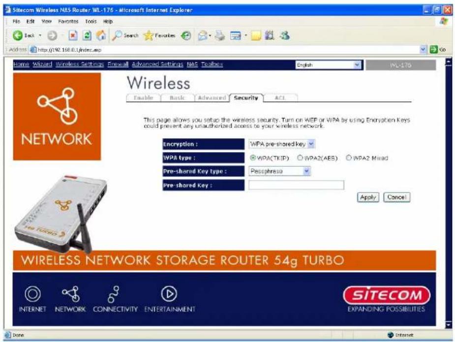
| Parameter s | Desc r i p ti on |
| WPA(TKIP) | TKIP can change the encryption key frequently to enhance the wi r el ess LAN sec u r i ty . |
| WPA2(AES) | This use CCMP protocol to change encryption key frequently. AES can p r ovi de h i g h l evel en c r y p ti on to en h an c e t h e w i r eless LAN sec u |
| WPA2 Mixed | This will use TKIP or AES based on the other communication peer au tomati c al l y . |
| Pre-shared Key FormatYou may select to select Passphrase (alphanumeric format) or Hexadecimal Digits (in the "A-F", "a-f" and "0-9" range) to be the Pre-shared Key. For example: Passphrase: iamguestHexadecimal Digits: 12345abcde | |
| Pre-shared Key | The Pre-shared key is used to authenticate and encrypt data transmitted in the wireless network. Fill the text box by following the rules below. Hex WEP: input 64-digit Hex values (in the "A-F", "a-f" |
Please check www.sitecom.com for up to date drivers & utilities, manuals and support
and "0-9" range) or at least 8 character pass phrase as to pre-sh ar ed keys.
7.3.4 WPPARadius
Wi-Fi Protected Access (WPA) is an advanced security standard. You can use an external RADIUS server to authenticate wireless stations and provide the session key to encrypt data during communication. It uses TKIP or CCMP(AES) to change the encryption key frequently. This can improve security very much.
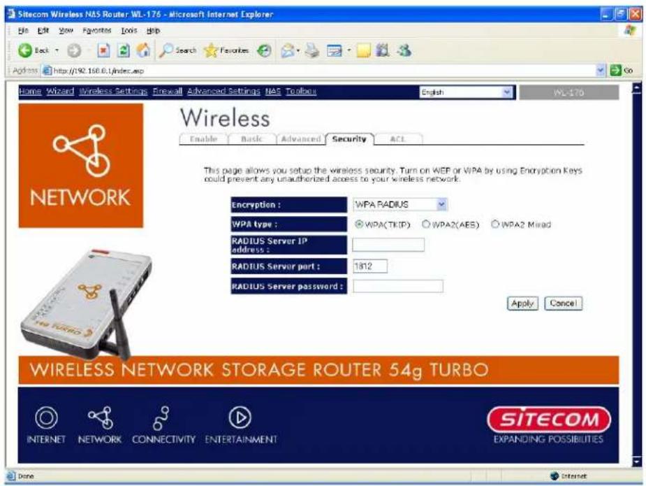
| Parameters | Description |
| WPA(TKIP) | TKIP can change the encryption key frequently to enhance the wi r el ess LAN sec u r i ty . |
| WPA2(AES) | This use CCMP protocol to change encryption key frequently. AES can provide high level encryption to enhance the wireless LAN sec u ri ty . |
| WPA2 Mixed | This will use TKIP or AES based on the other communication peer automatic c al l y . |
| RADIUS Server IP address | The IP address of external RADIUS server. |
| RADIUS Server Port | The service port of the external RADIUS server. |
| RADIUS Server Password | The password used by external RADIUS server. |
Click
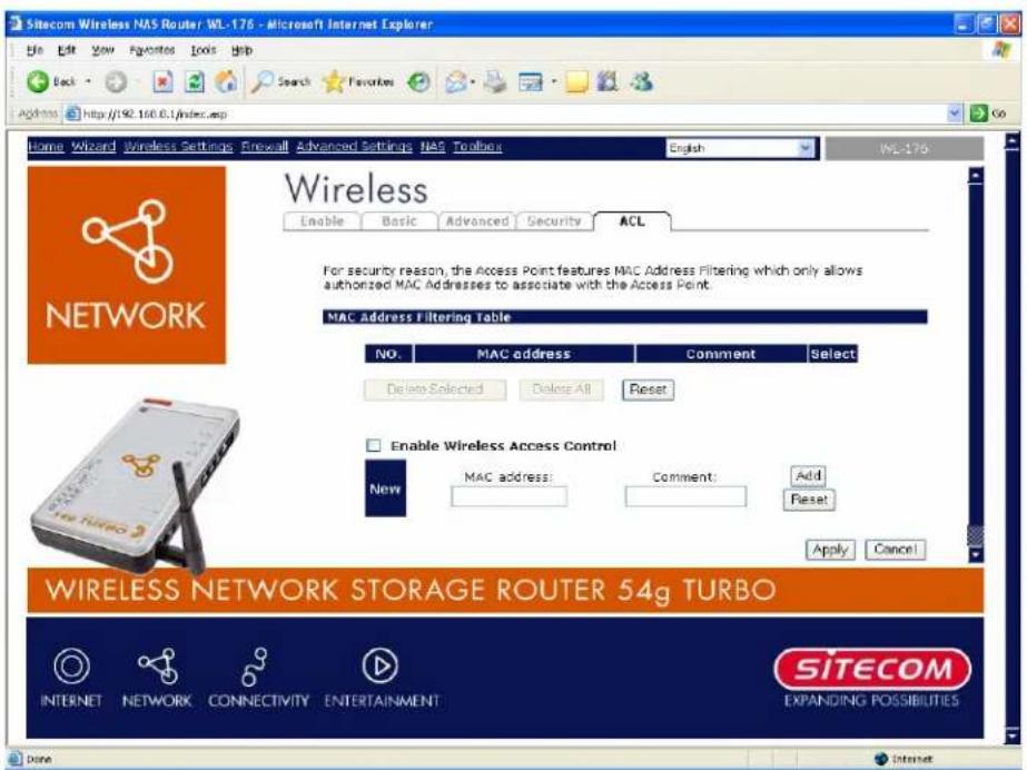
7.4 Access Control
This wire less router provides MAC Address Control, which prevents the unknown or addresses from accessing your wire less network.
| Par ameter s | Desc r i p ti on |
| Enable wireless access control | Enable wireless access control |
| Add MAC address into the list | Fill in the "MAC Address" and "Comment" of the wireless station to be added and then click "Add". Then this wireless station will be added into the "Current Access Con tr ol Li st" b el ow. If y ou f i nd an y i ssu es b ef or e addi i t and w a n t to r ety p e ag ai n . J u st c l i c k " C l ear " and b ot " MAC Addr ess" and " Comment t" f i el ds wi l l b e c l ear ed. |
| Remove MAC address from the list | If you want to remove some MAC address from the "Current Access Control List ", select the MAC addresses you want to remove in the list and then click "Delete Selected". If you want remove all MAC addresses from the table, just click "Delete All" button. Click "Reset" will c l ear y ou r c u r r e n t sel ec ti on s. |
Click
8 Firewall Settings
The Broadband router provides extensive firewall protection by restricting connection parameters, thus limiting the risk of hacker attack, and defending against a wide array of common Internet attacks. However, for applications that require unrestricted access to the Internet, you can configure a specific client/server as a Demilitarized Zone (DMZ).
Note: To enable the Firewall settings select Enable and click Apply
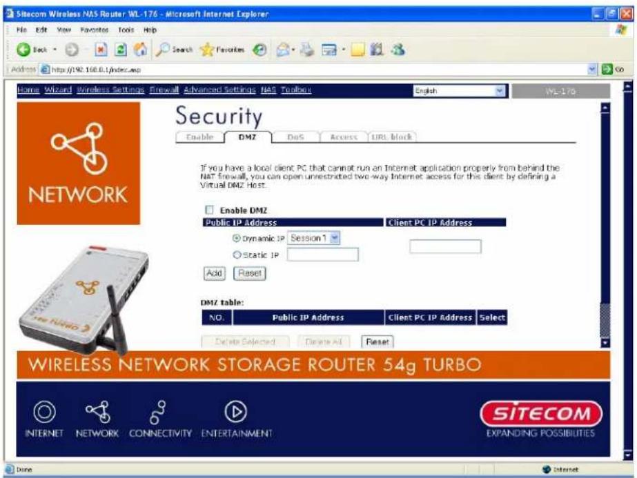
8.1 DMZ
If you have a local client PC that cannot run an Internet application (e.g. Games) properly from behind the NAT firewall, then you can open the client up to unrestricted two-way Internet access by defining a DMZ Host. The DMZ function allows you to re-direct all packets going to your WAN port IP address to a particular IP address in your LAN. The difference between the virtual server and the DMZ function is that the virtual server re-directs a particular service/Internet application (e.g. FTP, websites) to a particular LAN client/server, whereas DMZ re-directs all packets (regardless of services) going to your WAN IP address to a particular LAN client/server.
Parameter s ADesc r i p ti on
En ab l e DMZ AEn ab l e/ di sab l e DMZ
Note:
If there is a conflict between the Virtual Server and the DMZ setting, then Virtual Server function will have priority over the DMZ function.
Public IP Address The IP address of the WAN port or any other Public IP addresses given to you by your ISP
Client PC IP Address Input the IP address of a particular host in your LAN that will receive all the packets originally going to the WAN port/Public IP address above
Note:
You need to give your LAN PC clients a fixed/static IP address for DMZ to work properly.
You can now configure other advance sections or start using the router (with the advance settings in place)
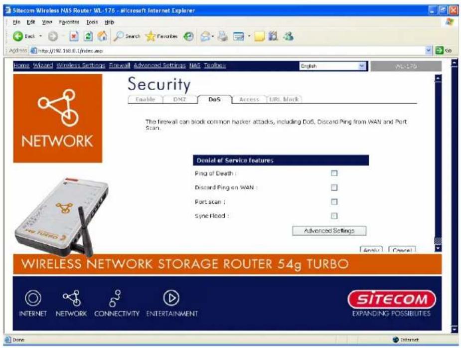
8.2 Do S At t ac k
The Broadband router's firewall can block common hacker attacks, including Denial of Service, Ping of Death, Port Scan and Sync Flood. If Internet attacks occur the router can log th e ev en ts.
| Parameter s | Desc r i p ti on |
| Pi ng of Death | Pr otec ti on sf r om Pi ng of Death attack k |
| Di sc ar d Pi ng Fr om WAN | Th er ou ter 's WAN port wi l l not r esp on d to any Pi ng r eq |
| Por t Sc an | Pr otec ti on th er ou ter f rom Port Sc an . |
| Sy n c Flo ood | Pr otec ti on th er ou ter f rom Sy n c Flo ood attack k . |
Click
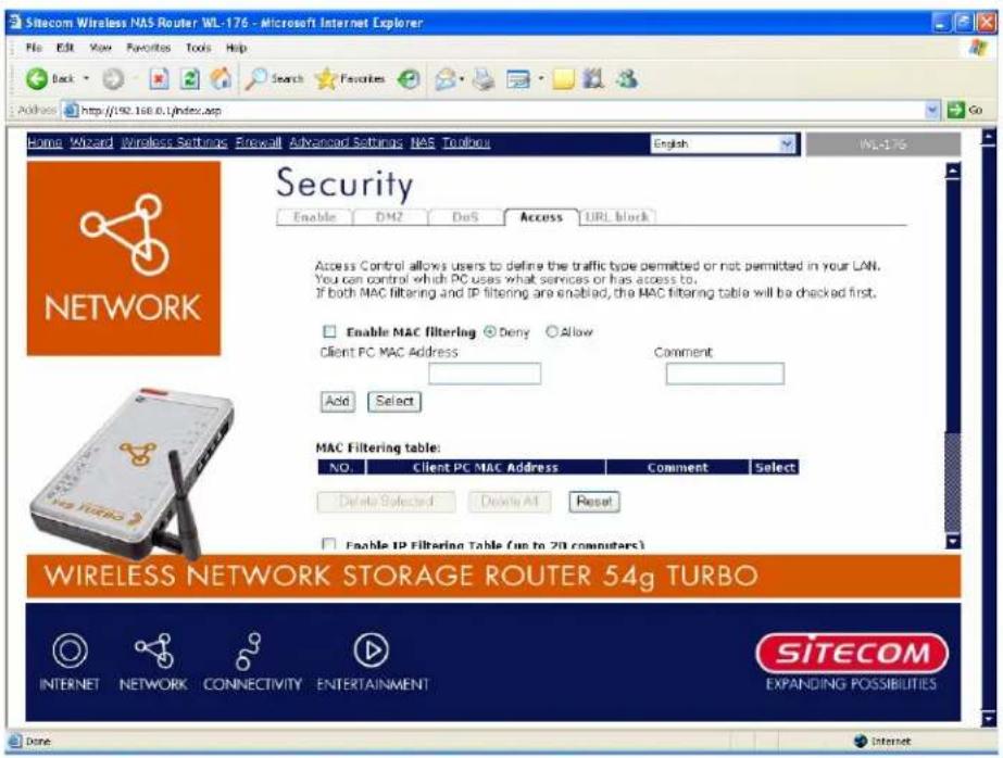
8.3 Access Control
If you want to restrict users from accessing certain Internet applications/services (e.g. Internet websites, email, FTP etc.), then this is the place to set that configuration. Access Control allows users to define the traffic type permitted in your LAN. You can control which PC client can have access to these services.
| Par ameter s | Desc r ip tion |
| Deny | If you select "Deny" then all PCs will be allowed to access Internet accept for the PCs in the list below. |
| Allow | If you select "Allow" then all PCs will be denied to access Internet accept for the PCs in the list below. |
| Filter client PCs by IP | Fill in "IP Filtering Table" to filter PC clients by IP. |
| Add PC | You can click Add PC to add an access control rule for users by IP addr esses. |
| Remove PC | If you want to remove some PC from the "IP Filtering Table", select the PC you want to remove in the table and then click "Delete Selected". If you want remove all PCs from the table, just click "Delete All" button. |
| Filter client PC by MAC | Check "Enable MAC Filtering" to enable MAC Filtering. |
Si tec om Wi r el ess Networ k Stor ag e Router 54g Tur b o WL-1 76
| Add PC AFi l i n " Cl i en t PC MAC Addr ess" and " Commen t" of the PC th at i s all I owed to ac c ess the In ter n et, and d then c l i ck " Add". If y ou f any typo before adding it and want to retype again, just click " Reset" and th e fi el ds w i ll b e c l ear ed. | |
| Remove PC | If you want to remove some PC from the "MAC Filtering Table", select the PC you want to remove in the table and then click " Del ete Sel ec ted" . If y ou want to r emov e al l PCs f r om th e tab l e, just click the "Delete All" button. If you want to clear the selection and re-select again, just click "Reset". |
You can now configure other advance sections or start using the router (with the advance settings in place)
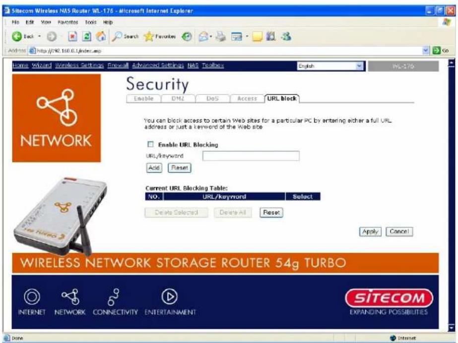
8.4 URL Block
You can block access to some Web sites from particular PCs by entering a full URL address or just key word of the Web site.
| Parameters | Description |
| En ab l e URL B1 oc ki n g | En ab l e/ di sab l e URL B1 oc ki n g |
| Add URL Keyword | Fill in "URL/Keyword" and then click "Add". You can enter the full URL address or the keyword of the web site you want to block. If you find any typo before adding it and want to retype again, just click "Reset" and the field will be cleared. |
| Remove URL Keyword | If you want to remove some URL keyword from the "Current URL Blocking Table", select the URL keyword you want to remove in the table and then click "Delete Selected". If you want remove all URL keyword from the table, just click "Delete All" button. If you want to clear the selection and re-select ag ai n , j u st c l i c k " Reset". |
You can now configure other advance sections or start using the router (with the advance settings in place)
9 P P Advanced Settings
Network Address Translation (NAT) allows multiple users at your local site to access the Internet through a single Public IP Address or multiple Public IP Addresses. NAT provides Firewall protection from hacker attacks and has the flexibility to allow you to map Private IP Addresses to Public IP Addresses for key services such as Websites and FTP. Select Disable to disable the NAT function.
Note:
If you disable the NAT function, it's only possible to access the internet from one PC at a time.
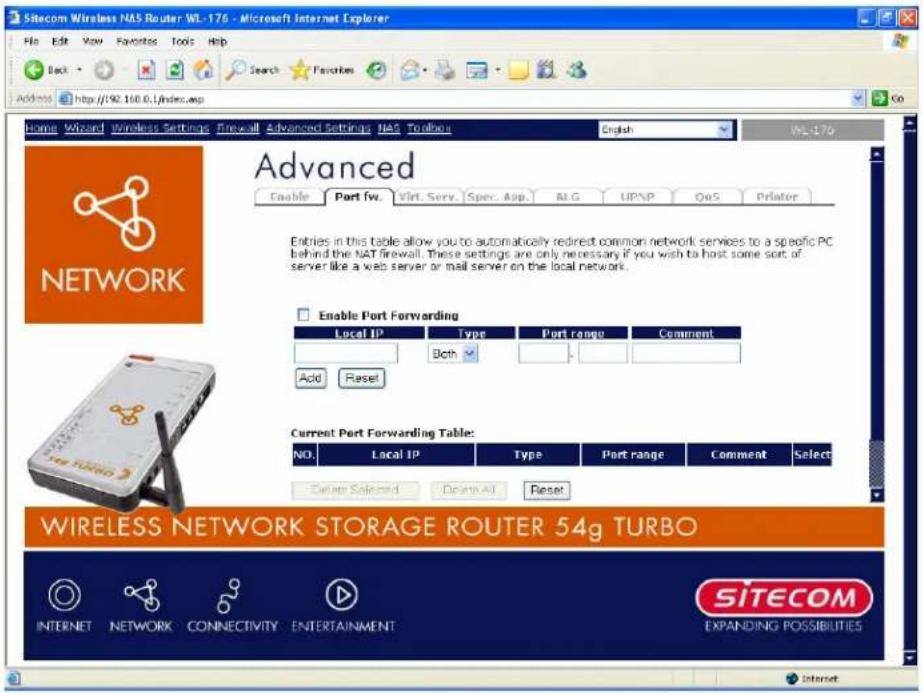
9.1 Port Forwarding
The Port Forwarding allows you to re-direct a particular range of service port numbers (from the Internet/WAN Ports) to a particular LAN IP address. It helps you to host some servers behind the router NAT firewall.
| Parameter | Description |
| Enable Port Forwarding | Enable Port Forwarding |
| Private IP | This is the private IP of the server behind the NAT firewall. |
Note:
You need to give your LAN PC clients a fixed IP address for Port Forwarding to work properly.
| Type | This is the protocol type to be forwarded. You can choose to forward "TCP" or "UDP" packets only or select "both" to forward both "TCP" and "UDP" packets. |
| Port Range | The range of ports to be forward to the private IP. |
| Comment | The description of this setting. |
| Add Port Forwarding | Fill in the "Private IP", "Type", "Port Range" and "Comment" of the setting to be added and then click "Add". Then this Port Forwarding setting will be added into the "Current Port Forwarding Table" below. If you find any typo before adding it and want to retype again, just click "Clear" and the fields will be clear ed. |
| Remove Port Forwarding | If you want to remove some Port Forwarding settings from the "Current Port Forwarding Table", select the Port Forwarding settings you want to remove in the table and then click "Delete Selected". If you want remove all Port Forwarding settings from the table, just click "Delete All" button. Click "Reset" will clear your current selection s. |
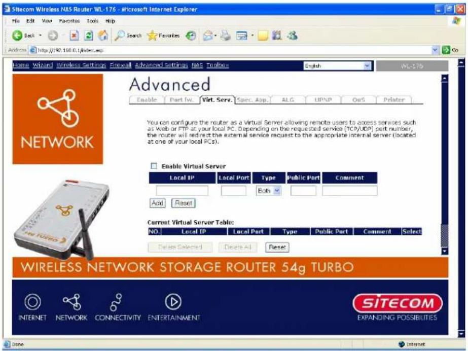
9.2 Virtual Server
Use the Virtual Server function when you want different servers/clients in your LAN to handle different service/Internet application type (e.g. Email, FTP, Web server etc.) from the Internet. Computers use numbers called port numbers to recognize a particular service/Internet application type. The Virtual Server allows you to re-direct a particular service port number (from the Internet/WAN Port) to a particular LAN private IP address and its service port number. (See Glossary for an explanation on Port number)
| Parameters | Description |
| Enable Virtual Server | Enable Virtual Server. |
| Private IP | This is the LAN client/host IP address that the Public Port number packet will be sent to. |
Note :
You need to give your LAN PC clients a fixed/static IP address for Virtual Server to work properly.
Private Port This is the port number (of the above Private IP host) that the below Public Port number will be changed to when the packet enters your LAN (to the LAN Server/Client IP)
Type Select the port number protocol type (TCP, UDP or both). If you are
Please check www.sitecom.com for up to date drivers & utilities, manuals and support
| unsure, then leave it to the def au l t both protocol. | |
| Public Port | Enter the service (service/Internet application) port number from the Internet that will be re-directed to the above Private IP address host in your LAN |
Note:
| Virtual Server function will have priority over the DMZ function if there is a conflict between the Vi r tu al Ser v er and th e DMZ settin g s. |
| Comment | The description of this setting. |
| Add Virtual Server | Fill in the "Private IP", "Private Port", "Type", "Public Port" and "Comment" of the setting to be added and then click "Add". Then this Virtual Server setting will be added into the "Current Virtual Server Table" below. If you find any typo before adding it and want to retype again, j u s t c l i c k " C l ear " and t h e f i el ds w i l l b e c l ear ed. |
| Remove Virtual Server | If you want to remove some Virtual Server settings from the "Current Virtual Server Table", select the Virtual Server settings you want to remove in the table and then click "Delete Selected". If you want remove all Virtual Server settings from the table, just click "Delete All" button. Click "Reset" will clear your current selections. |
Click
9.3 Special Applications
Some application on request multiple connection, such as Internet games, video Internet telephony and others. In this section you can configure the router to support multiple connections for these types of applications.
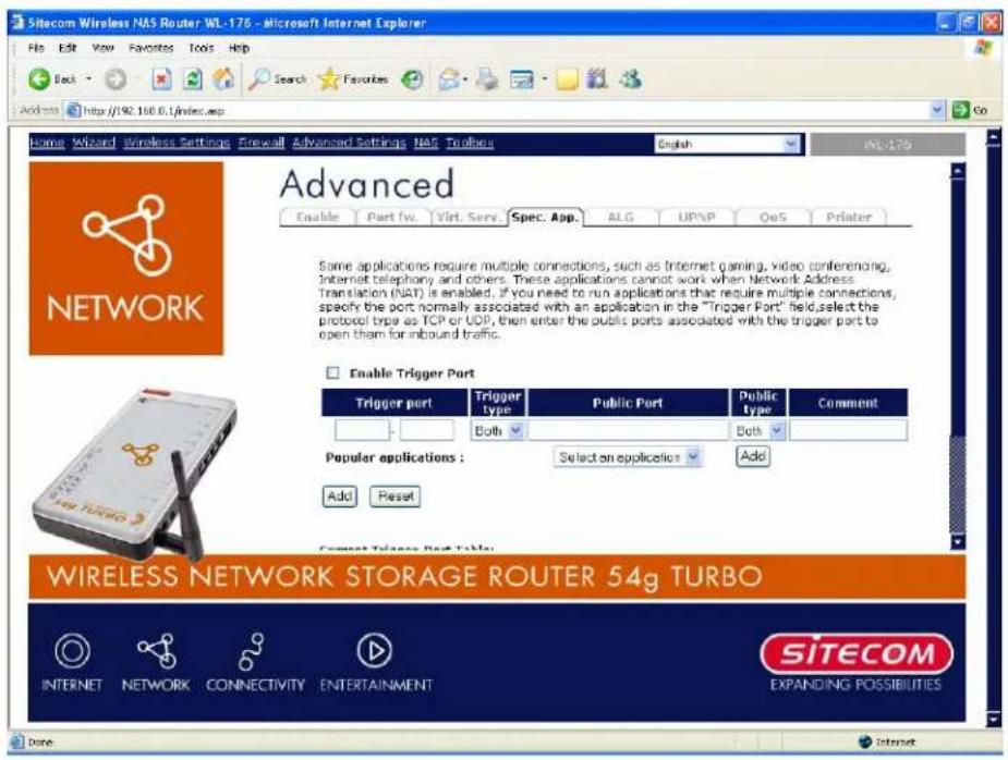
| Par ameter s | Desc r i p ti on |
| Enable Trigger Port | Enable the Special Application function. |
| Trigger Port | This is the out going (Outbound) range of port numbers for this particular application . |
| Trigger Type | Select whether the outbound port protocol is “TCP”, “UDP” or both. |
| Public Port | Enter the In-coming (Inbound) port or port range for this type of application (e.g . 230 0 -240 0 , 47624) |
Note :
Individual port numbers are separated by a comma (e.g. 47624, 5775, 6541 etc.). To input a port range use a "dash" to separate the two port number range (e.g. 2300-2400)
Public Type Select the Inbound port protocol type: "TCP", "UDP" or both Comment The description of this setting.
| Pop ul ar appl i c ati on s ATh i s sec ti on l i sts the m ore e pop ul ar appl i c ati on s th at r e multi p l e c o n n ec ti on s. Sel ect tan appl i c ati on f rom the Pop ul a Appl i c ati on s sel ec ti on . On c e y ou h av e sel ec ted an appl i c ati o select a location (1-10) in theCopy toselection box and then click theCopy tobutton. This will automatically list the Public Portsr equi r ed f or this s pop ul ar appl i c ati on i n the l oc ati on (1 - 1 spec i fi ed. | |
| Add Special Application | Fill in the "Trigger Port", "Trigger Type", "Public Port", "Public Type", "Public Port" and "Comment" of the setting to be added and then c l i c k " Add". Then this S pecial App li c ati on setti ng w i ll be the "Current Trigger-Port Table" below. If you find any typo before adding it and want to retype again, just click "Clear" and the fields w i ll be c l ear ed. |
| Remove | If you want to remove some Special Application settings from the " Current Trigger-Port Table", select the Special Application settings you want to remove in the table and then click "Delete Selected". If you want remove all Special Appliacation settings from the table, just click "Delete All" button. Click "Reset" will clear your current sel ec ti on s. |
Example: Special Applications
If you need to run applications that require multiple connections, then specify the port (outbound) normally associated with that application in the "Trigger Port" field. Then select the protocol type (TCP or UDP) and enter the public ports associated with the trigger port to open them up for inbound traffic.
Example:
| ID | T rigger Port | T rigger T yp e | Pub lic Port | Pub lic Type | Comment |
| 1 | 28800 | UDP | 2300-2400, 47624 | TCP | MSN Game Zone |
| 2 | 6112 | UDP | 6112 | UDP | Battle.net |
In the example above, when a user trigger's port 28800 (outbound) for MSN Game Zone then the router will allow incoming packets for ports 2300-2400 and 47624 to be directed to that user. Note: Only one LAN client can use a particular special application at a time.
9.4 ALG Settings
You can select application sth at need "Application Layer Gateway" to support.
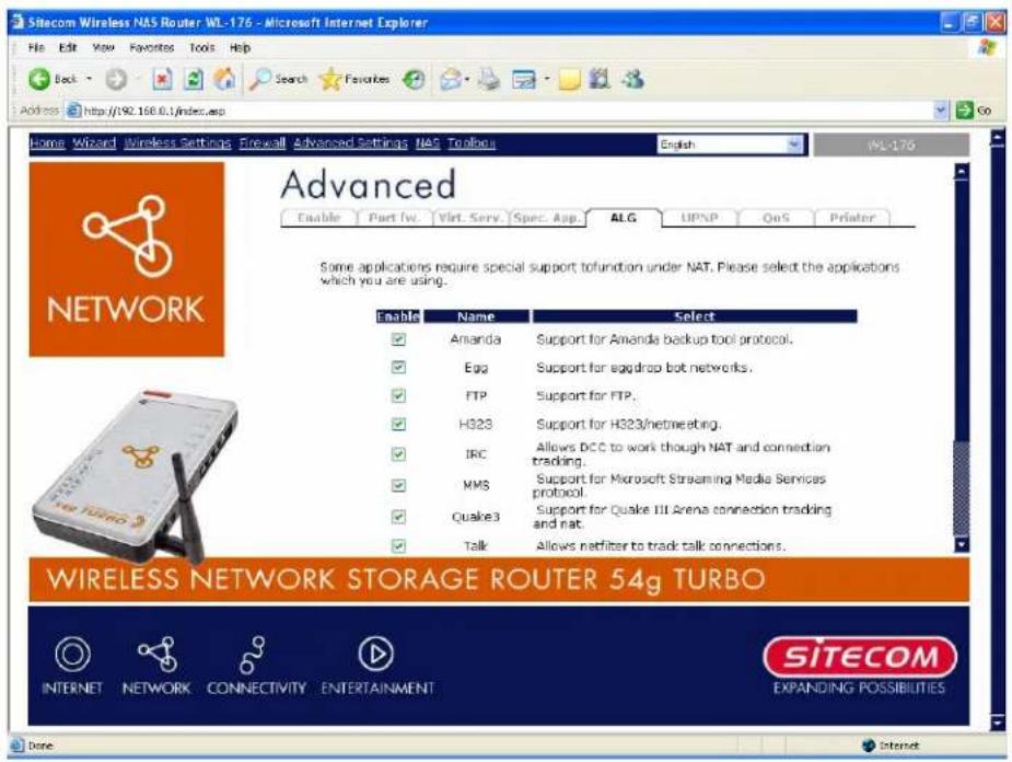
Parameter s ADesc r i p ti on
Enable You can select to enable "Application Layer Gateway", then the router will let th at ap p l i c ati on c or r ec tl y p ass th ou g h th e NAT g ateway.
9.5 UPnP Settings
With UPnP, all PCs in you Intranet will discover this router automatically. So you do not have to do any configuration for your PC and can access the Internet through this course
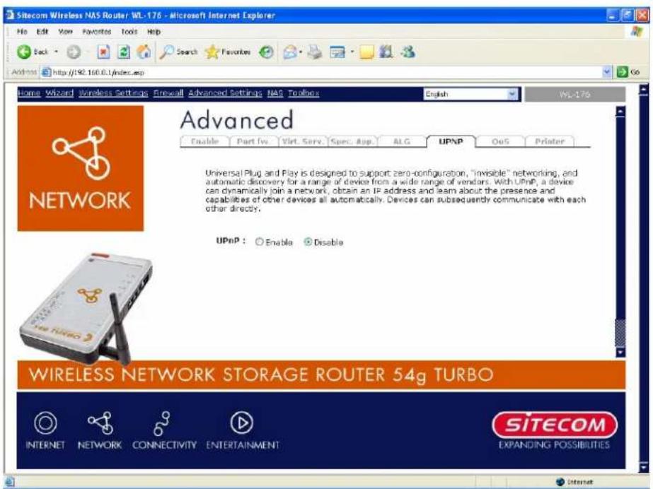
| Parameters | Default | Description |
| UPnP Feature | Disable | You can Enable or Disable UPnP feature here. After you enable the UPnP feature, all client systems that support UPnP, like Windows XP, can discover this r ou ter au tomati c al l y and d ac c ess th e In ter n et th r ou g h this router without any configuration. The NAT Traversal function provided by UPnP can let ap p l i c ati on s th at su p p or t UPnP smooth l y c on n ec t to Internet sites without any incompatibility problem due to th e NAPT p or t tr an sl ati on . |
9.6 QoS
The QoS can I et you classify In ter net application on traffic by source/destination port number. You can assign priority for each type of application and reserve bandwidth for it. The packets of applications with higher priority will always go first. Low applications will get bandwidth after higher priority applications get enough bandwidth. This can I et you have a better experience using critical real time services like video conference ...etc. All the applications not specified by you are classified as rule name "Others". The rule with a smaller priority number has a higher priority; the rule with a larger priority number has a lower priority. You can adjust the priority of the rules by moving them up or down.
Note :
If the total assigned bandwidth of higher priority applications is larger than bandwidth provided by the WAN port, the other application will not get any bar
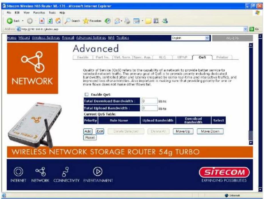
| Par ameter s | Desc r i p ti on |
| Enable/Disable QoS | You can check "Enable QoS" to enable QoS function for the WAN p or t. You al so c an u n c h e c k "En ab l e QoS" to dis a b l e QoS f u n c ti on f or th e WAN p or t. |
| Add a QoS rule in to the tab l e ACl i ck " Add" then y ou will enter af or m of the QoS r Click " Apply " after filling out thef or mand ther uI added in to the tab l e. | |
| Remove QoS rules from the tab l e If you want to remove some QoS rules from the tab l e select the QoS rules you want to remove in the tab l e and then click " Delete Selected". If you want remove all QoS rules from the tab l e, just click " Delete All " button .C " Reset" will clear your current selections. | |
| Edit a QoS rule | Select the rule you want to edit and click "Edit", then you will enter the detail f or m of the QoS rule. Click " Appl after editing thef or mand therulewill be saved. |
| Adjust QoS rule priority | You can select the rule and click "Move Up" to make its priority higher. You also can select the rule and click "Move Down" to make its priority lower. |
Edit QoS Rule:
You can assign packet classification criteria by its local IP range, remote IP range, traffic type, protocol, local port range and remote port range parameters. The parameters that you leave as blank will be ignored. The priority of this rule will be applied to packets that match
classificati on criteria of this rule. You can limit bandwidth consumed by p this rule or guar an tee band width required by packets that match this rule.
| Par ameter s | Desc r i p ti on |
| R u l e Name | Th e n ame of th i s r u l e. |
| Bandwidth | You can assign the download or upload bandwidth by the unit of Kbps (1024 bit per second). You can limit the maximum bandwidth consumed by this rule by selecting "Maximum". You also can reserve en ou g h b an dwi dth f or th i s r u l e b y sel ect t i n g " Gu ar an tee". |
| Local IP Address | Enter the local IP address range of the packets that this rule will apply to. If you assign 192.168.0.3 - 192.168.0.5, it means 3 IP addresses: 1 92.1 68.0 .3, 1 92.1 68.0 .4 and 1 92.1 68.0 .5 |
| Local Port Range | Enter the local port range of the packets that this rule will apply to. You c an assi g n a si n g l e p o r t n u m b er h e r e o r assi g n a r a n g e of numbers by assigning the first port number and the last port number of t h e r a n g e. Th e two n u m b er s a r e separ ated b y a dash " -", f or example " 1 0 1 -1 50" mean s f rom p o r t n u m b er 1 0 0 to p o r t n u m b er 1 50 - t h e r a n g e of 50 p o r t n u m b er s. |
| Remote IP Address | Enter the remote IP address range of the packets that this rule will apply to. If you assi g n 1 92.1 68.2.3 - 1 92.1 68.2.5, i t mean s 3 IP addr esses: 1 92.1 68.2.3, 1 92.1 68.2.4 and 1 92.1 68.2.5 |
Si tec om Wi r el ess Networ k Stor ag e Router 54g Tur b o WL-1 76
| Remote Port Range | AEnter theremote port range of the packets that at this rule will apply. You can assign a single port number here or assign a range of numbers by assigning the first port number and the last port of therange. The two numbers are separated by a dash “-”, for example “101-150” means from port number 100 to port number 150 -therange of 50 port numbers. |
| Traffic Type | Select the traffic type of the packets that this rule will apply to. We list some popular application on her to ease the configuration. You can get the same result by using other parameters, for example source or destination port number, if you are familiar with the application protocol. |
| Protocol | Select the protocol type of the packets that this rule will apply to. |
| Apply | Apply and exit the form. |
| Reset | Clear the content of this form. |
9.7 Print Server
The router provides Print Server function that let you share a printer to all PCs on your network. It supports LPD printing protocol which can be used in Windows, Linux and other OS th at p r ovide LPD p r in ti n g .
Note:
The Print Server function is disabled by default for better performance of the NAS function.
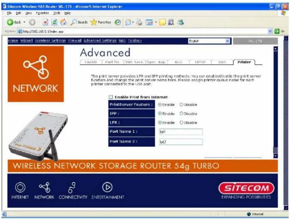
| Parameters | Description |
| Enable Print from Internet | Check on “Enable Print from Internet” to share printer on internet or check off this option to use printer on your LAN. |
| Print Server Feature | Enable/disable USB print server. The print server function is default disabled for better performance of the NAS function. |
| IPP | Enable to support the Internet Printing Protocols |
| LPR | Enable to support the Local Printing Remote. |
| Port Name 1 | It is the name of the printer port. Each printer port has to be assigned a name. The client utility uses this name to access the p r in ter p or t. |
Si tec om Wi r el ess Networ k Stor ag e Router 54g Tur b o WL-1 76
Port Name 2 It is then a name of the printer port. Each printer port has to be assigned a name. The client utility uses this name to access the printer port.
10 NAS System
The NAS function lets you share a USB storage device to all PCs in your network / Internet. It supports Samba, let you share files via Windows Network Neighborhood. And also supports FTP server for your FTP clients to upload / download files from the server.
10.1 General Settings
General settings is used to set sharing information of samba and can be used to manage users' information, including adding, editing and deleting users' information.
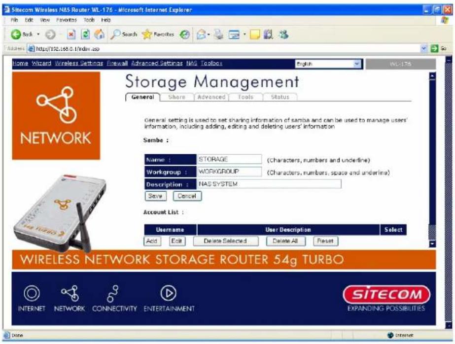
| Parameters | Description |
| Name | The host name that is visible in 'network neighborhood'. |
| Workgroup | The network neighborhood workgroup that you want to join. |
| Description | A brief description for this NAS router. This will be shown in the detailed information of network neighborhood. |
| Add Account | Add a new user account. |
| Edit Account | Edit the selected user account. |
| Delete Account | Delete the selected / all user account. |
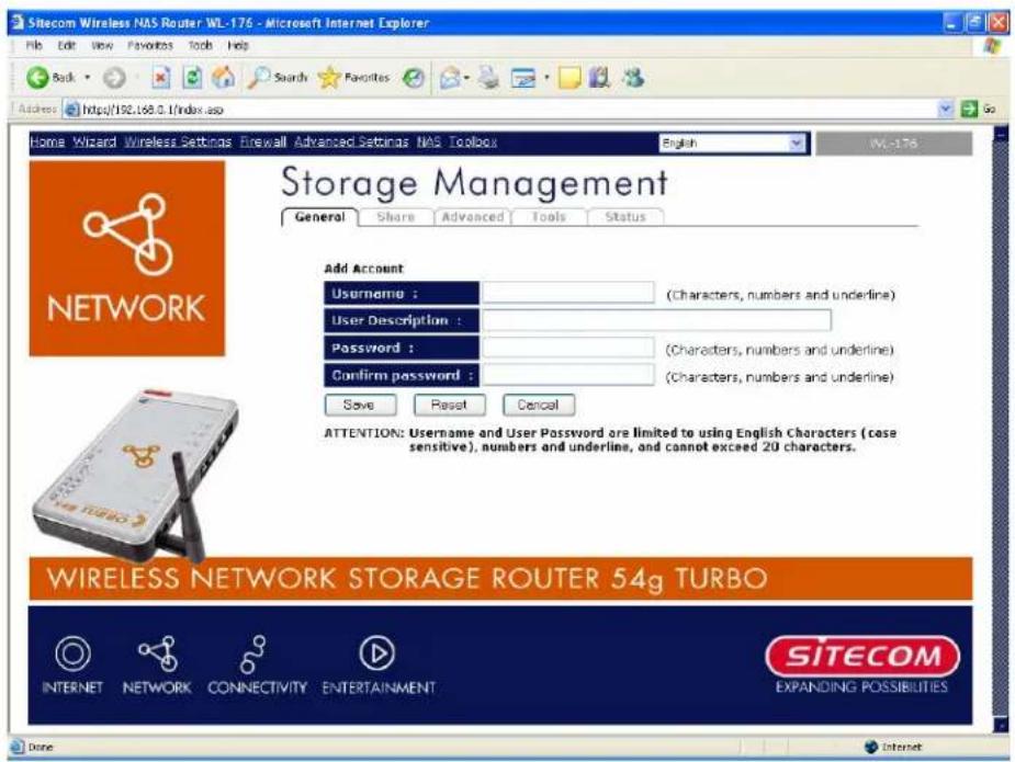
Parameter s A Description
User name AThe user name you want to add. A
User Description A brief description for this user.
Password The password for this user account.
Confirm Password Re-type the password for this user account.
Note:
There should be at least one user account added before sharing the USB storage device through Samb a and FTP. A
Note:
The maxi mu num ber of supported user accounts 32. A
1 0.2 Share
This page shows the status of all the shares on the NAS device. You can add, edit and download the shares of items.
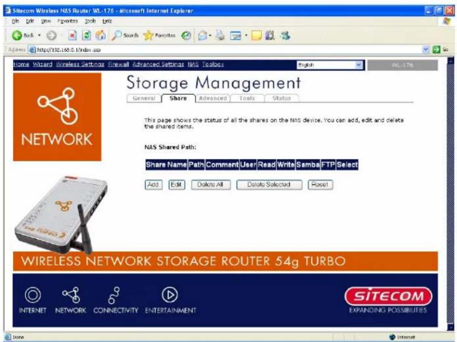
Parameter s A Description
Add Share
Add a new shar ed i tem.
Edit Share
Edit the selected shared items.
Delete Share
Delete the selected / all shared items.
10.2.1 Add Shares
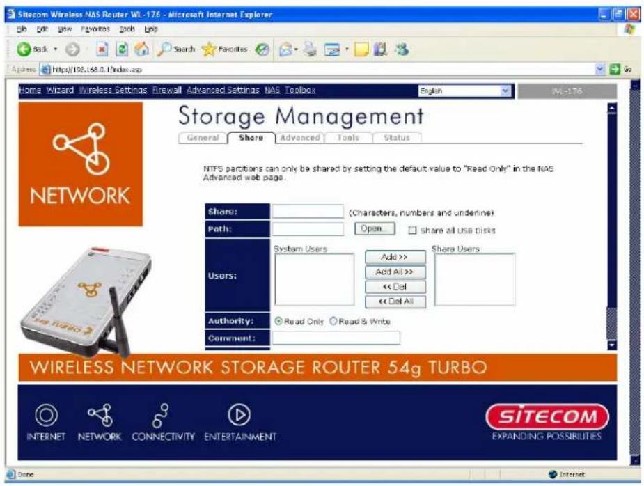
Parameter s A Description
Share AThen ame for this share. A
Path Select th e sh ar ed p ath.
Users Select which user scan access this share. A
Authority Set the access right (Read Only or Read & Write) for this share.
Comment A brief description for this share. A
Shared To The method of sharing such as via Network Neighborhood (Samba) and d / or FTP. A A
Note:
Each user can only be added to one single FTP share. A A
Note:
The NTFS partitions cannot be shared in this way and it can only be shared as Read Only. For details please refer to the next session 10.3 Advanced.
10.2.2 Select Share Path
When you click the Open button, you can see the following pop-up window that shows the USB storage devices. Please select the USB devices from the left panel. The directories on this USB storage device will be shown in the right bottom panel. Choose the folder that you want to share, and click Submit to select this folder for sharing. You can also click New Folder to create a new folder for sharing.
![http://192.168.0.1 - NAS Download - Microsoft Internet Explorer Path : [USB1]C\ Submit USB1 Return New Folder Movies Music Pictures Cancel Done Internet](/content/2026/06/1150173/images/d59eac50b6a80f820c1458b79e95eb28cf7366497bde4604d699bf38ca2394f7.jpg)
Note:
Only folders will be shown and shared. Files aren't visible in this window.
1 0.3 Adv anc e d
Adv an c ed setti n g i s u sed to set th e p r o p er ti es of FTP ser v er and d th e def au l t sh ar e setti n ew USB stor ag e dev i c es.
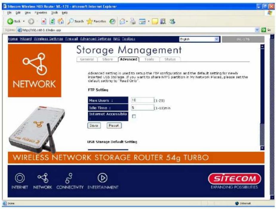
Parameter s ADesc r i p ti on
| Max Users | The maximum number of users that can connect to the FTP Ser v er si mu l tan eou sl y . |
| Idle Time | The FTP client will be disconnected automatically after it is i n ac ti v e f or th i s Idl e Ti me. |
| Internet Accessible | Check it if you want to allow access to the FTP Server through th e In ter n et. |
| USB Storage Default Setting | Select the default sharing setting for the newly plugged USB storage device. You can share the USB Storage Device as Read & Wr i te, Read On l y , or Don ’t Sh ar e b y def au l t. |
Note:
For NTFS partitions please follow the below steps to share it.
-
Unplug the USB storage device that contains NTFS partitions.
-
Set the USB Storage Default Setting to Read Only.
- Pl u g -i n th e USB stor ag e dev i c e th at c on tai n s NTFS p ar ti ti on s ag ai n |
Note:
NTFS parti ti on s can only b es har ed as Read Only .
1 0.4 NAS Tools
This page shows the status of all I c on n ec ted USB stor ag e dev i c es and d al so al l ows u ser man ag e th e USB stor ag e dev i c e (For mat an d Add / Remov e Par ti ti on s). A
Note:
USB1 p or t i s dedi c ated f or th e USB stor ag e dev i c e u sed f or th e NAS r ou ter (u su all y th is brand new or there's no need to be moved to other PC environments), you can use the NAS tool s to p ar ti ti on and d for mat th e USB stor ag e dev i c e.
USB2 port is for the USB flash disk or storage disk which you usually used to share data in different places. If needed, you can partition and format it in your favorite PC environment.
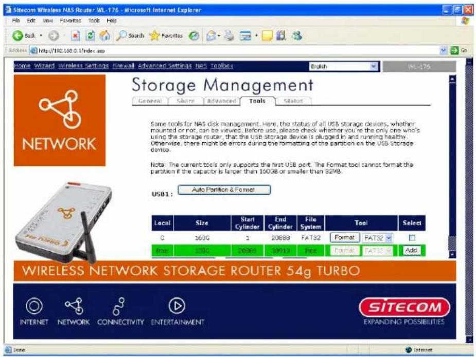
| Parameter s | Desc r i p ti on |
| Auto Partition & Format | The USB storage disk plugged in USB1 port will be partitioned and for matted au tomati c al l y. A |
| Tool | The USB storage disk can be formatted in FAT32 / FAT16 / EX T2. A |
| Add | Add a n ew p ar ti ti on on th e USB stor ag e di sk . |
| Remove Partition | Remove the selected / all partitions on the USB storage disk. |
Note:
The maximum supported partition size for FAT32 and EXT2 is 160GB, while that for FAT16 is 2GB.
Note:
Although the NAS router does not support formatting a USB storage disk into NTFS format, you still can plug-in USB storage disk with NTFS partitions (formatted by PC) and share it as Read Only.
Note:
The Auto-partition & Format function will delete all the existing partitions on the USB storage disk before partitioning & formatting.
If the USB storage disk is bigger than 160GB, it will automatically partition the USB storage disk into several partitions with each partition size 160GB and then format all partitions.
If the USB storage disk is smaller than 160GB, there will be one single partition.
10.4.1 Add Partitions
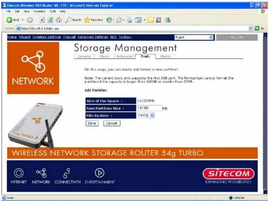
Parameter s ADesc r i p ti on
| Size of the Space AThis is the total free space that you can use. A A | |
| New Partition Size | Set the size of the new partition. |
| File System | The partition can be formatted in FAT32 / FAT16 / EXT2. |
1 0.5 NAS S t at us
This Page shows the status of attached USB storage devices.
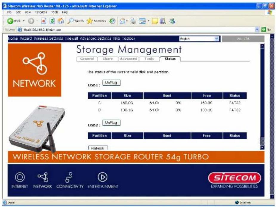
| Par ameter s ADesc r i p ti on | |
| Partition | The partition name of the USB storage device. |
| Si z e | Th e si z e of th at p ar ti ti on . |
| Used | The total used space of that partition in both byte count and p er c en tag e of th e total sp ac e. |
| Fr ee | Th e f r ee sp ac e l ef t i n th at p ar ti ti on . |
| Status | The type of the partition, such as FAT32 / FAT16 / EXT2 / NTFS. |
1 1 Toolbox
You can change the password required to log in to the broadband and router's system management. By default, there is no password. So please assign a password to the
Admi ni str ator as soon as possi ble, and stor e it i n a saf e pl ac e. Passwor ds c an c on tai al ph an u mer i c c har ac ter s, and ar e c ase sen si ti ve.
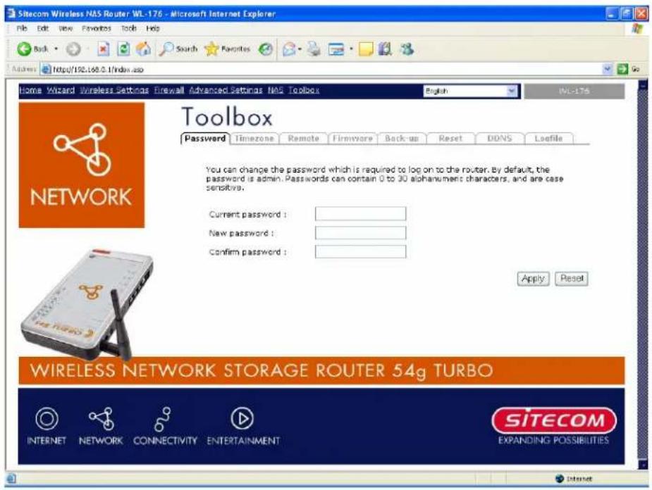
| Par ameter s | Desc r i p ti on |
| Current Password | Enter your current password for the remote management admi ni str ator to l og i n to y ou r Br oadb and r ou ter . |
| New Password | Enter your new password |
| Confirmed Password | Enter your new password again for verification purposes |
Note:
If you forget your password, you'll have to reset the router to the factory default (password is admin) with the reset button (see router 's b ac k p an el).
Click
11.1 Time zone
The Time Zone allows your router to reference or base its time on the settings configured here, which will affect functions such as Log entries and Firewall settings.
![Sitecom Wireless NAS Router WL-176 - Microsoft Internet Explorer File Edit View Favorites Tools Help Back Search Favorites Access https://192.168.0.1/index.asp Home Wizard Wireless Settings Firewall Advanced Settings NAS Toolbox English WL-176 Toolbox Password Timezone Remote Firmware Back-up Reset DONS Logfile SET the time zone of the broadband router. This information is used for log entries and firewall settings. Set Time Zone : [GMT]Greenwich Mean Time: Dublin, Edinburgh, Lisbon, London Time Server Address : 192.43.244.18 Daylight Saving : Enable From January To January Apply Reset WIRELESS NETWORK STORAGE ROUTER 54g TURBO INTERNET NETWORK CONNECTIVITY ENTERTAINMENT SITECOM EXPANDING POSSIBILITIES Done Internet](/content/2026/06/1150173/images/60821cb10e99b42b6b18080f5890092cb811074f46e44981af90d7081e1834db.jpg)
| Parameter | Description |
| Set Time Zone | Select the time zone of the country you are currently in. The router will set its time based on your selection. |
| Time Server Address | The router default the “Time Server Address” is “1 92.43.244.1 8” |
| Enable Daylight Savings | The router can also take Daylight savings into account. If you wish to use this function, you must check/tick the enable box to enable your daylight saving configuration (below). |
| Start Daylight Savings Time | Select the period in which you wish to start daylight Savings Time |
| End Daylight Savings Time | Select the period in which you wish to end daylight Savings Time |
Click
11.2 Remote Management
There remote man ag ement f u n c ti on al l ows y ou to desi g n ate a h ost i n th e In ter n et th e ab c on f i g u r e t h e B roadb a n d r ou ter f r om a r emote si te. En ter th e desi g n ated h ost IP Addr th e Host IP Addr ess fi el d.
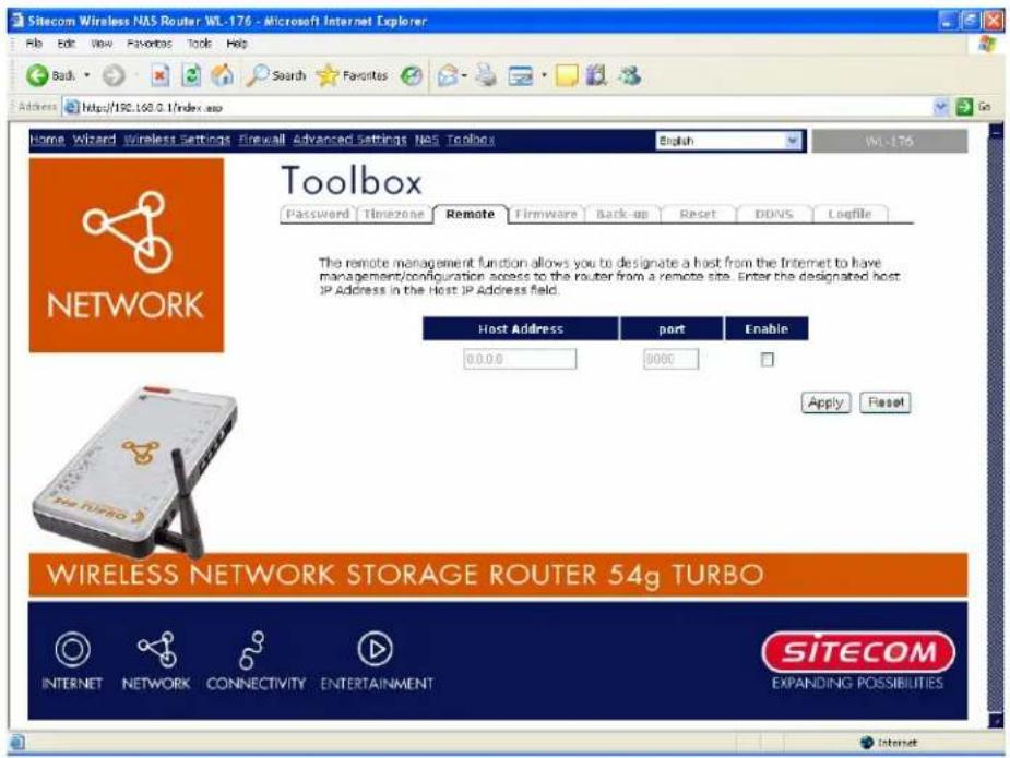
Par ameter s Desc r i p ti on
Host Address This is the IP address of the host in the Internet that will have man ag emen t/ c on f i g u r ati on ac c ess to th e Br oadb and r ou ter fr om a r em si te. Th i s mean s i f y ou ar e at h ome an d y ou r h ome IP addr ess h as b een designated the Remote Management host IP address for this router (located in your company office), then you are able to configure this router from your home. If the Host Address is left 0.0.0.0 this means anyone can access the router's web-based configuration from a remote location, p r ovi di n g they k now the p assw or d.
C lic k the E nab le d b ox to enable the Remote Management function.
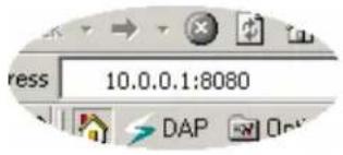
Note:
When you want to access the web-based management from a remote site, you must enter the router's WAN IP address (e.g. 10.0.0.1) into your web-browser followed by port number 8080, e.g. 10.0.0.1:8080 (see below). You'll also need to know the password set in the
Please check www.sitecom.com for up to date drivers & utilities, manuals and support
Password Setting screen in order to access the router's web-based management.
Port The port number of remote man ag ement web i n ter f ac e.
Enabled Select "Enabled" to enable the remote management function.
Click
11.3 Firmware Upgrade
This page all ows you to upgrade ther outer 'sf i r mware.
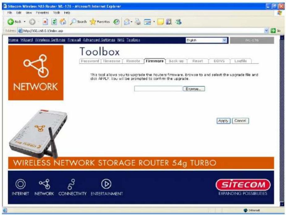
| Par ameter s | Desc r i p ti on |
| Firmware Upgrade | This tool allows you to upgrade the Broadband router's system firmware. To upgrade the firmware of your Broadband router, you need to download the firmware file to your local hard disk, and enter th at fi l en ame an d p ath i n the a p p r o p r i ate f i el d on th i s p ag e. Y o also use the Browse button to find the firmware file on your PC. |
Once you've selected the new firmware file, click
11.4 Backup Settings
The Backup screen allows you to save (Backup) the router's current configuration setting. Saving the configuration settings provides an added protection and convenience should problems occur with the router and you have to reset to factory default. When you save the configuration setting (Backup) you can re-load the saved configuration into the router through the Restore selection. If extreme problems occur you can use the Restore to Factory Defaults selection, this will set all configurations to its original default settings (e.g. when you first purchased the router).
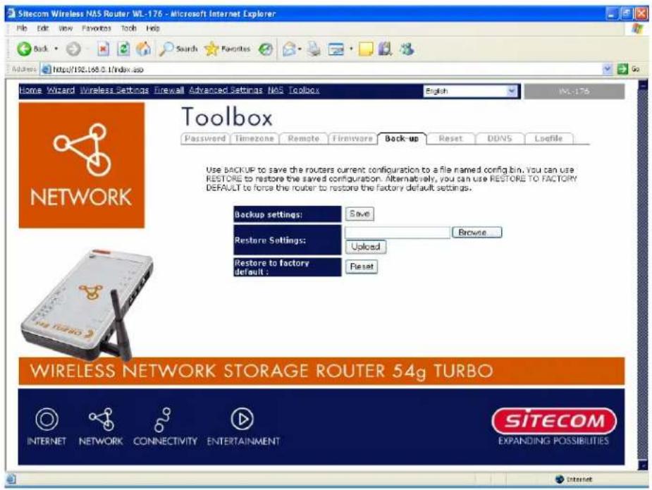
| Parameter s | Desc r i p ti on |
| Configuration Tools | Use the "Backup" tool to save the Broadband router current configuration to a file named "config.bin" on your PC. You can then use the "Restore" tool to restore the saved configuration to the Broadband router. Alternatively, you can use the "Restore to Factory Defaults" tool to force the Broadband router to perform a power reset and restor e the or i g i nal f ac tor y setti n g s. |
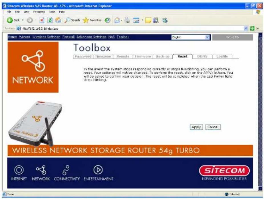
11.5 Reset (restart) the router
You can reset the router's system should any problem exist. The reset function essentially Re-b oots y ou r rou ter's sy stem.
Note:
Your settings will NOT be changed by the system-reboot.
11.6 DDNS
DDNS al I ows y ou to map the static domain name to a dy n ami c IP address. You must get an account, Ap asswor d Aan d Ay ou r Astatic Adomai n An ame Af r om Ath e ADDNS Aser vice Apr ou ter sup p or ts Dy n DNS, TZ O and other common DDNS ser vice pro vi der s.
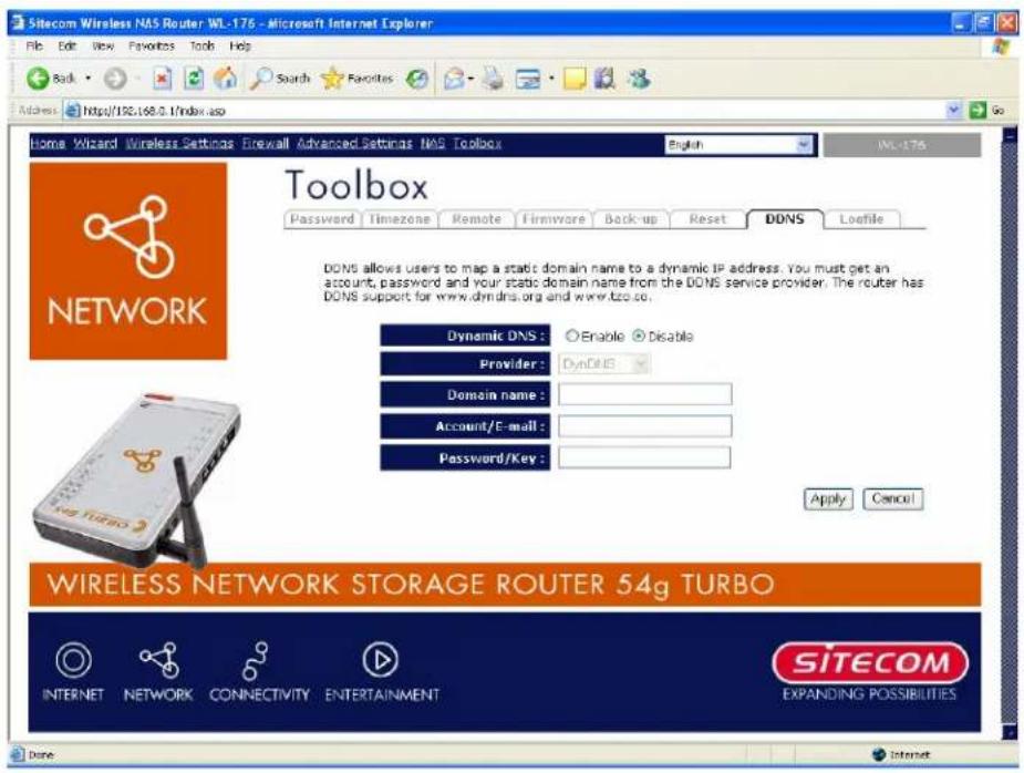
| Par ameter s | Desc r i p ti on |
| Enable/Disable | Enable/Disable the DDNS function of this router |
| Pr ov ider A A A A A | Sel ec t a DDNS ser v i c e p rovi der |
| Domain n ame A | Y ou r stati c domai n name th at u se DDNS |
| Account/E-mail | The account that your DDNS service provider assigned to you |
| Password/Key | The password you set for the DDNS service account above |
Click
Appendix A
How to manually find your PC's IP and MAC address
1) In Win dow's open the Command Prompt program
2) Type ipconfig /all and
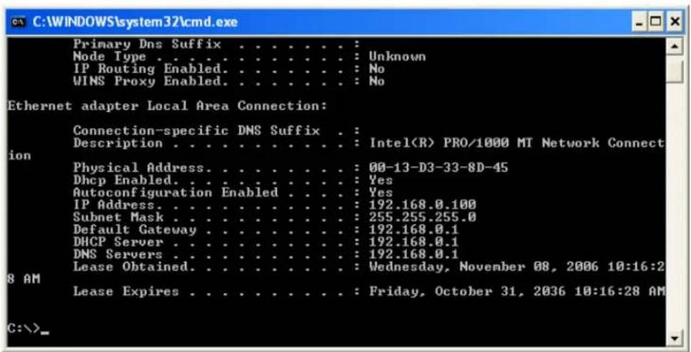
- Your PC's IP address is the one entitled IP address (e.g. 192.168.0.100)
- The router's IP address is the one entitled Default Gateway (e.g. 192.168.0.1)
- Your PC's MAC Address is the one entitled Physical Address (e.g. 00-13 -D 3 -3 3 -8 D -4 5)
Glossary
Default Gateway (Router): Every non-router IP device needs to configure a default gateway's IP address. When the device sends out an IP packet, if the destination is not on the same network, the device has to send the packet to its default gateway, which will then send it out towards the destination.
DHCP: Dynamic Host Configuration Protocol. This protocol automatically gives every computer on your home network an IP address.
DNS Server IP Address: DNS stands for Domain Name System, which allows Internet servers to have a domain name (such as www.Broadbandrouter.com) and one or more IP addresses (such as 192.34.45.8). A DNS server keeps a database of Internet servers and their respective domain names and IP addresses, so that when a domain name is requested (as in typing "Broadbandrouter.com" into your Internet browser), the user is sent to the proper IP address. The DNS server IP address used by the computers on your home network is the location of the DNS server your ISP has assigned to you.
DSL Modem: DSL stands for Digital Subscriber Line. A DSL modem uses your existing phone lines to transmit data at high speeds.
Ethernet: A standard for computer networks. Ethernet networks are connected by special cables and hubs, and move data around at up to 10/100 million bits per second (Mbps).
Idle Timeout: Idle Timeout is designed so that after there is no traffic to the Internet for a pre-configured amount of time, the connection will automatically be disconnected.
IP Address and Network (Subnet) Mask: IP stands for Internet Protocol. An IP address consists of a series of four numbers separated by periods, that identifies a single, unique Internet computer host in an IP network. Example: 192.168.0.1. It consists of 2 portions: the IP network address, and the host identifier.
The IP address is a 32-bit binary pattern, which can be represented as four cascaded decimal numbers separated by “.”: aaa.aaa.aaa.aaa, where each “aaa” can be anything from 000 to 255, or as four cascaded binary numbers separated by “.”: bbbbbbbb.bbbbbbbb.bbbbbbbb.bbbbbbbb, where each “b” can either be 0 or 1.
A network mask is also a 32-bit binary pattern, and consists of consecutive leading
1's followed by consecutive trailing 0's, such as
1111111.1111111.1111111.00000000. Therefore sometimes a network mask can also be described simply as "x" number of leading 1's.
When both ar e r ep resen ted si de b y si de i n the i r b i n ary f or ms, all b it s i n the If c or r esp on d Ato A1 's Ai n Ath e An etwor k mask b ec ome Ap a r t Aof Ath e AIP An etwor k Aaddr r emai n ing b i ts c or r esp on d to the h ost ID. A
For example, if the IP address for a device is, in its binary form,
1 1 0 1 1 0 0 1 .1 0 1 1 0 0 0 0 .1 0 0 1 0 0 0 0 .0 0 0 0 0 1 1 1 , and if its network mask is, 1 1 1 1 1 1 1 1 .1 1 1 1 1 1 1 1 .1 1 1 1 0 0 0 0 .0 0 0 0 0 0 0
It means the device's network address is A
1 1 0 1 1 0 0 1 .1 0 1 1 0 0 0 0 .1 0 0 1 0 0 0 0 .0 0 0 0 0 0 0 0 , and i ts h ost ID i s, 00000000.00000000.00000000.00000111. This is a convenient and efficient method for r ou ter s to r ou te IP p ac k ets to their desti n ati on .
ISP Gateway Address: (see ISP for definition). The ISP Gateway Address is an IP address for the Internet outer located at the ISP's office. A
ISP: Internet Service Provider. An ISP is a business that provides connectivity to the Internet for i ndi vi du al s and oth er b u si n esses or or g an i z ati ons. A
LAN: Local Area Network. A LAN is a group of computers and devices connected together in a relatively small area (such as a house or an office). Your home network is considered a LAN.
MAC Address: MAC stands for Media Access Control. A MAC address is the hardware address of a device connected to a network. The MAC address is a unique identifier for a device with an Ethernet interface. It is comprised of two parts: 3 bytes of data that corresponds to the Manufacturer ID (unique for each manufacturer), plus 3 bytes that are of ten u sed as the e p r odu c t's ser i al n u m ber .
NAT: Network Address Translation. This process allows all of the computers on your home network to use one IP address. Using the broadband router's NAT capability, you can access the Internet from any computer on your home network without having to purchase more IP addresses from your ISP. A
Port: Network Clients (LAN PC) uses port numbers to distinguish one network application/protocol over another. Below is a list of common applications and protocol/port numbers:
| Application | on | PortoNumber |
| Tel net | TCP | 23 |
| FTP ATCP A21 | ||
| SMTP ATCP A25 | ||
| POP3 ATCP A1 1 0 | ||
| H.323 | TCP A1 720 | |
| SNMP | UCP | 1 61 |
| SNMP Tr ap | UDP | 1 62 |
| HTTP | TCP A80 | |
| PPTP | TCP A1 723 | |
| PC Any where | TCP A5631 | |
| PC Any where | UDP | 5632 |
PPPoE: Point-to-Point Protocol over Ethernet. Point-to-Point Protocol is a secure data transmission method originally created for dial-up connections; PPPoE is for Ethernet connections. PPPoE relies on two widely accepted standards, Ethernet and the Point-to-Point Protocol. It is a communications protocol for transmitting information over Ethernet between different manufacturers
Protocol: A protocol is a set of rules for interaction agreed upon between multiple parties so that when they interface with each other based on such a protocol, the interpretation of their behavior is well defined and can be made objectively, without confusion or misu n der stan ding .
Router: A router is an intelligent network device that forwards packets between different networks based on network layer address information such as IP addresses.
Subnet Mask: A subnet mask, which may be a part of the TCP/IP information provided by your ISP, is a set of four numbers (e.g. 255.255.255.0) configured like an IP address. It is used to create IP address numbers used only within a particular network (as opposed to valid IP address numbers recognized by the Internet, which must be assigned by InterNIC).
TCP/IP, UDP: Transmission Control Protocol/Internet Protocol (TCP/IP) and Unreliable Datagram Protocol (UDP). TCP/IP is the standard protocol for data transmission over the Internet. Both TCP and UDP are transport layer protocol. TCP performs proper error detection and error recovery, and thus is reliable. UDP on the other hand is not reliable. They both run
Si tec om Wi r el ess Networ k Stor ag e Router 54g Tur b o WL-1 76
on top of the IP (In ter n et Prot o col ), a n etw or k l ay er p r ot o col .
WAN: Wide Area Network. A network that connects computers located in geographically separate areas (e.g. different buildings, cities, countries). The Internet is a wide area network.
Web-based management Graphical User Interface (GUI): Many devices support a graphical user interface that is based on the web browser. This means the user can use the familiar Netscape or Microsoft Internet Explorer to Control/configure or monitor the device b ein g man ag ed.