EG25XR-PRO - Állvány E-Image - Ingyenes használati útmutató
Találja meg az eszköz kézikönyvét ingyenesen EG25XR-PRO E-Image PDF formátumban.

Felhasználói kérdések a következőről EG25XR-PRO E-Image
0 kérdés erről a készülékről. Válaszolj azokra, amiket ismersz, vagy tedd fel a sajátod.
Tegyél fel egy új kérdést erről a készülékről
Töltse le az útmutatót a következőhöz Állvány PDF formátumban ingyenesen! Találja meg kézikönyvét EG25XR-PRO - E-Image és vegye vissza elektronikus eszközét a kezébe. Ezen az oldalon közzé van téve az eszköze használatához szükséges összes dokumentum. EG25XR-PRO márka E-Image.
HASZNÁLATI ÚTMUTATÓ EG25XR-PRO E-Image

SUPPORT YOUR IMAGE

E-IMAGE
EG25XR PRO
Virtual Head Tracking System With Tripod
natural_image
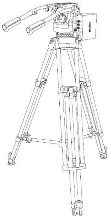
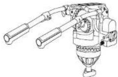
Line drawing of a tripod-mounted surveying instrument with dual levers and control panel (no text or symbols)NINGBO EIMAGE STUDIO EQUIPMENT CO., LTD
Add: No.1230 South Cihai Rd, Luotuo Industry zone, Zhenhai,
Ningbo, China. 315202
Tel:+86-574-86590031/86590061
E-mail: sales@eimagevideo.com
Visit www.eimagevideo.com for more information

E-IMAGE
Official QR Code
www.eimagevideo.com
Contents
Contents
Safety Instructions 1
Product Introduction 2
In the Box 3
Specification 4
GH25XR PRO Head 5
ECT100L Tripod 6
Head Date Synchronization Acquisition Box 7
Using 9
Problems and Solution 10
Warranty Card 12
Safety Instructions
Introduction
Safety Instructions
Thanks for purchasing E-IMAGE EG25XR PRO products.
We encourage you to read this manual carefully to familiarize yourself with all the detailed features before operating it, as some of them may be new to you. The manual includes all safety instructions, operation guidelines, and maintenance procedures. Please ensure that all equipment is operated correctly to avoid any defects or damage, especially ensuring that the tripods are steady, and the head is securely locked and leveled.
- In order to avoid non recovery after wrong operation, please back up the original configuration file before modifying in tf card.
- Please make sure all cables are with correct interface.
- Please connect all the cables before power on.
- Please make sure lock the cables connector tightly, in case any fall off or poor contact, influence normal using of whole device.
- Inspecting focus/zoom gear teeth wear in every 3-6 months is suggested. Please change it if the central hole is worn or loose touching with lens. (Operation: camera is turn off. Please hold on the focus lens or zoom lens of camera, dial the focus or zoom gear softly, if no loose, the central hole is normal. In the whole movement, the focus/zoom gear disc will work closely while the lens is turning. If not, please change the gear disc.)
- Please lock the tripod leg tightly before mounting camera on.
- Please make sure the head is locked tightly on the tripod.
- Please remove the camera from tripods for transportation.
Product Introduction
EG25XR PRO virtual tripod system is self-developed high-performance virtual head measuring system. It is an important component subsystem of VR and MR system. The virtual system is combined by Video tripod, Virtual head, Head date synchronization acquisition box, zoom/focus encoder module and DC power. It is used for collecting the data of pan & tilt angle of head, zoom & focus of camera. The system sends virtual data (the pan & tilt angle of head, zoom & focus of camera) to the image processing device in real time according to the synchronization signal inputs of video live. The data are send with RS422 or LAN interface, all conform to FREE-D protocol.
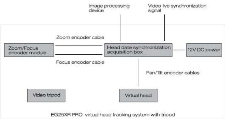
flowchart
graph TD
    A["Video tripod"] --> B["Focus encoder cable"]
    C["Virtual head"] --> D["Head date synchronization acquisition box"]
    E["12V DC power"] --> D
    F["Image processing device"] --> D
    G["Video live synchronization signal"] --> D
    H["Zoom/Focus encoder module"] --> D
    I["Pan/Tilt encoder cables"] --> D
    J["Zoom encoder cable"] --> D
    K["EG25XR PRO virtual head tracking system with tripod"]
For the latest product information, please visit www.eimagevideo.com and click on the product page.


In the Box
Specification
The product packaging comes with the following items. In case any item is found missing, please contact E-IMAGE or your local sales agent.
natural_image
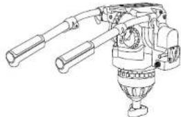
Technical line drawing of a mechanical device with articulated arms and a central hub (no text or symbols)GH25XR Pro Head
x1PC
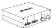
Head Date Synchronization Acquisition Box
×1PC


| Gear Module-0.5 | × 2 PCS |
| Gear Module-0.6 | × 2 PCS |
| Gear Module-0.8 | × 2 PCS |
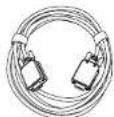
Output Line
×1PC
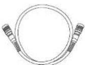

Pan/Tilt Date Cable
×1PC
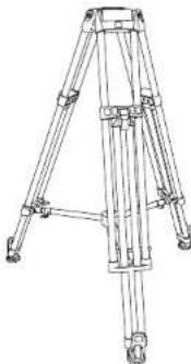
natural_image
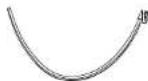
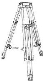
Technical line drawing of a tripod-mounted tripod structure with no visible text or symbolsECT100L Video Tripod
x1PC
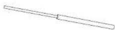
Zoom/Focus Encoder
×1PC
Universal Follow Focus Ring
×2 PCS
15mm Steel Rod Adapter
×2 PCS
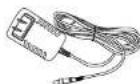
Power Adapter
×1PC
Specification
① Head specification
② Tripod specification
③ Head date synchronization acquisition box specification
| Model | GH25XR PRO |
| Payload Range | 25kg / 55lb |
| Counterbalance | 1-15 |
| Grades Of Pan Drag | 0-7 |
| Grades Of Tilt Drag | 0-7 |
| Tilt Range | -80^ - +90^ |
| Temperature Range | -30^ - +65^ |
| Bowl Size | 100mm |
| Net Weight | 4.2kg / 9.3lb |
| Model | ECT100L |
| Payload Range | 100kg/220.0lb |
| Height Range | 75.5cm~153cm/29.7in~60.2in |
| Transport Length | 92.5cm/36.4in |
| Bowl Size | 100mm |
| Sections | 2 |
| Material | Carbon fiber |
| Net Weight | 8kg/17.6lb |
| Model | 1080P |
| Supply Voltage | DC9-12V (Electrical) |
| Maximum Current Consumption | 1A |
| Pan / Tilt Resolution | 16 Bit Absolute(65,536 Count/Revolution) |
| Zoom / Focus Resolution | Up to 16 bit absolute(Effective Resolution: 13 bit absolute) |
| Communication Bus | RS422Speed:38400 bpsDate:8 bitsStop:1 bitParity:Odd |
| Communication Protocol | Free-D1 |
| Data Output Frequency | Depending On Genlock.Max Frequency 60Hz |
| LAN Connection | RJ45 (T568B) |
| Power | <10W |
| Temperature Range | 0-40°C |
| Humidity | RH 60%(25°C) |
| Size | 156x152x50mm6.1x6.0x2.0in |
| Net Weight | 530g/1.2lb |
GH25XR PRO Head
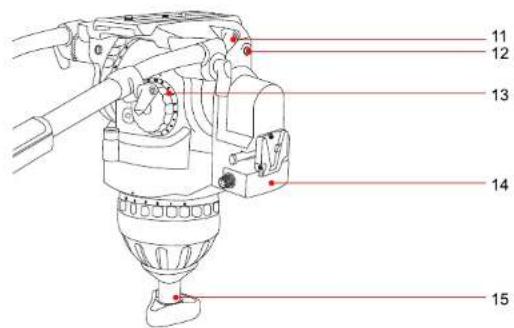
ECT100L Tripod
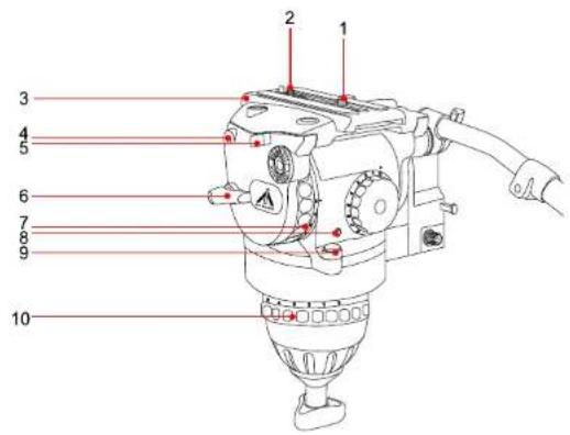
1.3/8" screw
2.1/4" screw
3. Camera plate
4.1/4" screw hole
5. Insurance button
6. Tilt locking knob
7. Tilt damping dial
8.Illuminous button
9.Bubble level
-
Pan damping dial
-
Camera plate locking knob
12.1/4" screw hole
- Counterbalance adjustment dial
14.V-lock mout adapter
15.Bowl locking knob
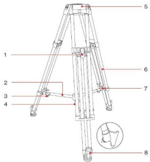
- Flip lock lever
2.Mid-level spreader - Length adjustment locking knob
- Angle adjusting bolt
5.Bowl base
6.Leg tube
- Transport belt
8.Rubber feet & Spiked feet


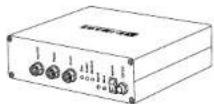
Head Date Synchronization Acquisition Box - Right Side
① Head date synchronization acquisition box - right side.
natural_image
Line drawing of a rectangular electronic device with ports and connectors (no text or symbols)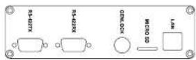
1-1: RS-422-TX
Date transfer connector, DB9 interface, RS-422 signal.
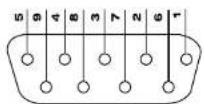
DB9 PIN No
| Pin No. | 1 | 2 | 3 | 4 | 5 |
| Definition | RX+ | RX- | TX+ | TX- | GND |
RS-422-TX PIN definition
1-2: RS-422-RX
Date receiver, DB9 interface, RS-422 signal. The PIN definition is same as transfer.
It is only used for retransmission Head date synchronization acquisition box.
1-3: GENLOCK
Sync signal input connector, BNC interface. The date can be output by connecting sync signal generator in default mode. The inner wire should be connected to Sync signal, and the shielded wire should be connected to GND.
1-4: MICRO SD
Micro SD card is inserted in.
Please power off when put the card in or take out.
The config. txt file is the system standard file. It can be edited by matched card reader.
1-5: LAN
LAN connect, RJ45 connector. UDP Internet system for outputting data.

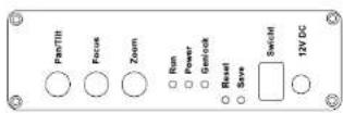
Head Date Synchronization Acquisition Box - Left Side
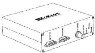
② Head date synchronization acquisition box - left side.
natural_image
Line drawing of a rectangular electronic device with four ports and a label (no readable text or symbols)2-1: Pan/Tilt
Pan/tilt connector, eight-cores aviation interface.
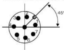
Eight-cores
sokect pin number
| Pin No. | 1 | 2 | 3 | 4 | 5 | 6 | 7 | 8 |
| Definition | 5V | 5V | Head Tilt RX- | Head Tilt RX+ | Head Pan RX- | Head Pan RX+ | GND | GND |
Head Parv/Tilt connector pin definition
2-2: Focus
Lens focus connector, eight-cores aviation interface, cmos signal. Zero port products without it.
| Pin No. | 1 | 2 | 3 | 4 | 5 | 6 | 7 | 8 |
| Definition | GND | 5V | SO | SI | CLK | CS | NC | NC |
Lens focus connector pin definition
2-3: Zoom
Lens Zoom connector, eight-cores aviation interface. The definition is same as focus.
2-4: Run
Run light indicator, the light flashes in every 2s if program runs well.
2-5: Power
Power indicator, it is continuous light on after power on.
2-6: Genlock
Sync input indicator, it is continuous light on if sync singal is inputting.
2-7: Reset
Reset bottom, by pressing it on 3 times continuously, the setted location of pan/tilt will be cleared.
2-8: Save
Store the last position of pan&tilt before power off
2-9: Switch
Power on/off.
2-10: 12V DC
12V DC power adapter.

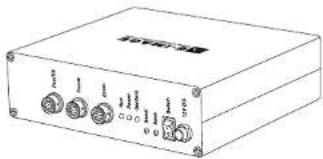
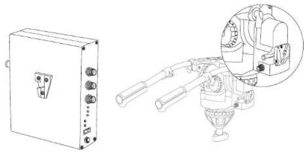
Head Date Synchronization Acquisition Box - Back Side
① Head date synchronization acquisition box - back side.
natural_image
Technical line drawing of an electrical enclosure and a mechanical device with a magnified inset showing internal components (no text or symbols)The back is with standard V-lock mount, which is used for installing it on virtual head by pulling it down, until hear "click".
Using
① Please assemble the tripod kit, camera, zoom/ focus module. Head date synchronization acquisition box, and other sync signal device and virtual software devices (sync device & virtual software is provided by customer).
② Please power on the Head date synchronization acquisition box.
③ Please open your software and related devices, the Head date synchronization acquisition box will send data to corresponding connector, finishing head data collecting.
Problems and Solution
① The power light is off.
| Reasons | Solutions |
| The input electric current problem | Please change the power |
| interface is loosed | Please tight it |
| The switch is not on | Turn it on |
| Other problem | Return back to factory |
② Run indicator light is off or continuous on.
| Reasons | Solutions |
| The micro controller is locked | Turn the power off, then turn on |
| TF card is broken | Copy the configuration file again or change the card |
| Other problem | Return back to factory |
③ Sync indicator light is off or flash.
| Reasons | Solutions |
| Sync signal input is not stable | Change to other sync source or change the sync cable |
| Connector is loosed | Make it tighter |
| Other problem | Return back to factory |
9
10
Problems and Solution
④ Date can't be received or the transmission continually.
| Reasons | Solutions |
| No signal access | Please access the signal |
| Date transfer or receiver connector is loosed | Make it tighter |
| Sync signal is not stable | Change to other sync source or change the sync cable |
| Sync signal connector is loosed | Make it tighter |
| Other problem | Return back to factory |
Customer Information
| Customer Name | Contact No. |
| Address |
Sales Manager
| Sales Date | Dealer |
| Dealer Contact No. |
1 Maintenance Record
| Service Date | Signature of Repairman | ||
| Cause of Problem | |||
| Service Result: □ Solved □ Unsolved □ Refunded/ Replaced | |||