NF-813 - Multiméter Noyafa - Ingyenes használati útmutató
Találja meg az eszköz kézikönyvét ingyenesen NF-813 Noyafa PDF formátumban.

Felhasználói kérdések a következőről NF-813 Noyafa
0 kérdés erről a készülékről. Válaszolj azokra, amiket ismersz, vagy tedd fel a sajátod.
Tegyél fel egy új kérdést erről a készülékről
Töltse le az útmutatót a következőhöz Multiméter PDF formátumban ingyenesen! Találja meg kézikönyvét NF-813 - Noyafa és vegye vissza elektronikus eszközét a kezébe. Ezen az oldalon közzé van téve az eszköze használatához szükséges összes dokumentum. NF-813 márka Noyafa.
HASZNÁLATI ÚTMUTATÓ NF-813 Noyafa

natural_image
Cartoon illustration of a mouse wearing a graduation cap and holding a pencil, giving a thumbs-up (no text or symbols)Your excellent helper in cable test!
MODEL: NF-803 SERIES NF-813 SERIES
Your excellent helper in cable test!
Wire Tracker INSTRUCTION MANUAL
natural_image
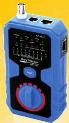
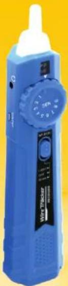
Blue handheld medical device with a dial and control knob, against a yellow background (no visible text or symbols)ORIGINAL AUTHENTIC

VER: V1
Table of Contents
- Brief Introduction......1
- Specification of Product....1
- Interfaces.....2
- Function & Operation....4
4.1.Wire Tracing....4
4.2.Network Cable Continuity test....5
4.3.Port Flash Function....8
4.4. Telephone line condition & Polarity test....9
4.5.Electric cable Countinuity test....10
- Accessories....10
- Function Compare Summary......11
1. Brief Introduction
Main Functions :
- Trace network cable, telephone cable BNC cable and electric cable.
- Network cable continuity test.
-
Port flash function directly find target cables connected with POE switch.
-
Specification of Product
| Transmitter Specification | NF-813 (A/B/C) | NF-803 (A/B) |
| The max. distance of cable mapping | 305M | 305M |
| Cable test types | RJ45, RJ11,BNC,Electric | |
| Tone mode | 2 Tones adjustable | |
| Max. Signal voltage | 8Vp-p | |
| Max. distance of transmission | 600m for RJ45 & RJ11;100m for BNC | |
| Protected against voltage | DC48V,5mA | |
| Battery type | 1.5V/9V/3.7V | 1.5V/9V |
| Size(mm) | 135*78*35mm | |
| Receiver Specifications | NF-813 (A/B/C) | NF-803 (A/B) |
| Port | RJ45-8P | |
| Battery type | 1.5V/9V/3.7V | 1.5V/9V |
| Size(mm) | 203*45*33mm | |
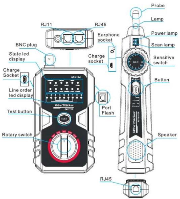
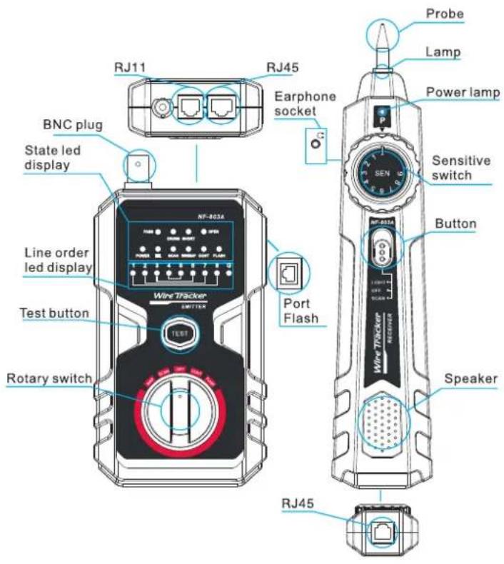
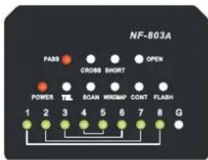
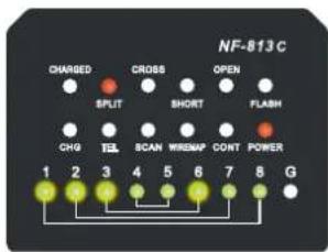
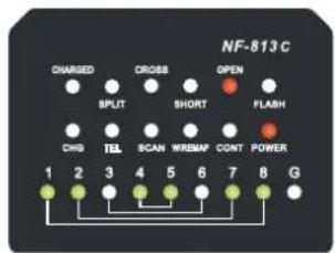
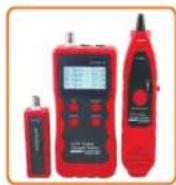
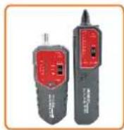
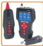
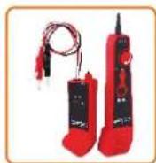
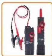
3. Interfaces:
Item No: NF-813C
Item No: NF-803A
4. Function & Operation
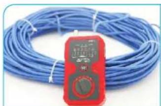
4.1.Wire Tracing
- Directly insert target line ( RJ45 , RJ11 or BNC cable ) into the corresponding port of emitter . For electricity wire , please insert wire clip to RJ11 into RJ11 port .connect electric wire with the clamp .
- Switch to the SCAN mode on emitter, and the power led is lit (if power lamp is off, check the batteries), scan led flicker. Press the test button, it would change the frequency of tracing signal.
natural_image
Blue wire with a red digital multimeter placed on its side (no visible text or symbols)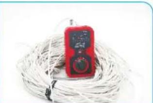
natural_image
Red handheld electronic device with a digital display, coiled with white cables (no visible text or symbols)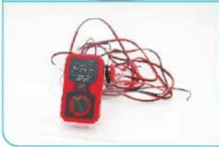
natural_image
Red and black handheld electronic device with coiled wires (no visible text or symbols)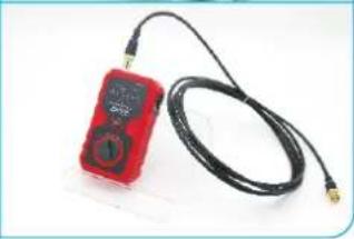
natural_image
Red handheld electronic device connected to a black cable with gold connectors (no visible text or symbols)- Push the button to SCAN mode (or LIGHT mode if work in dark condition), the power led is lit.
natural_image
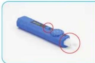
Blue cylindrical object with a small white mark and two red-circled annotations (no text or symbols visible)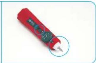
natural_image
Red handheld electronic device with a circular button, no visible text or symbols- Use the probe of receiver to trace wires according to the audio signals. You can adjust the sensitivity switch from 1 to 9 to locate the accurate position of wire.
natural_image
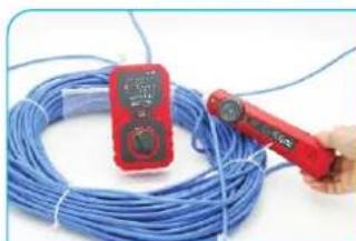
Close-up of a red handheld power tool handling a coiled blue cable, with no visible text or symbols.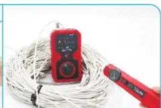
natural_image
Red handheld power tool with a red digital multimeter placed on coiled wire (no visible text or symbols)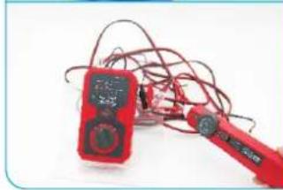
natural_image
Red and black handheld electrical clamp with wires, no visible text or symbols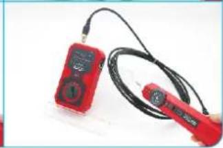
natural_image
Two red handheld devices with black cables, one holding a small device (no visible text or symbols)- Remember to turn off after using to save energy. Take out the 1.5v batteries if long time no use.
4.2. Network Cable Continuity test :
- Switch to MAP mode on emitter and the "power" & "wiremap" led light.
- Insert one end of network cable into emitter RJ45 port and another end to receiver RJ45 port.
- Press "TEST" button on emitter and the tester will check the continuity of the network cable.
- Result Instruction:
| Model NO. | NF-803 series | NF-813 series |
| PASS | PASS led light ,lamp 1 to 8 light . G for STP | NO PASS indicate, lamp 1 to 8 light . G for STP |
| SPLIT | NO | SPLIT led lights , lamp 1 to 8 light .G for STP |
| CROSS | CROSS led lights ,the leds corresponded to the cross lines will be flashing . | CROSS led lights ,the leds corresponded to the cross lines will be flashing . |
| SHORT | SHORT led lights ,the leds corresponded to the short lines will light all the time . | SHORT led lights ,the leds corresponded to the short lines will light all the time . |
| OPEN | OPEN led lights. the leds corresponded to the open line will be off . | OPEN led lights. the leds corresponded to the open pair will be off . |
PASS
line 1-2 3-6 SPLIT
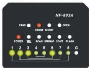
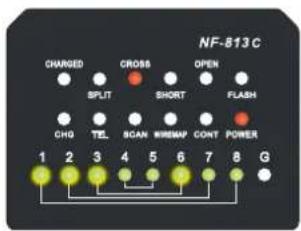
line 1-2 3-6 CROSS
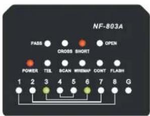
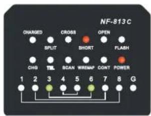
line 3-6 SHORT
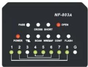
line 3 OPEN
4.3 Port Flash Function
This function should be used on condition that you know target line is connected with POE switch or router, but you don't know the exact plug it inserted.
- Switch to FLASH mode on emitter.
- Insert one end of network cable into emitter PORT FLASH port.
- The corresponding led on switch or router will be flashing in different frequency.
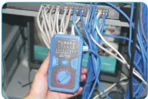
natural_image
Hand holding a blue multimeter in front of a networked server rack (no visible text or symbols)4.4 Telephone line condition & Polarity test a. telephone line condition test :
- Switch to OFF mode on emitter .Insert telephone line to RJ11 plug.
- Result Instruction :
| display | result |
| TEL led light turns green all the time | line is free |
| TEL led light in red and green alternately | line is ringing |
| No light | line is busy |
b. Positive and negative polarity test :
- Switch to OFF mode on emitter .Insert RJ11 - clips adaptor line to RJ11 plug .
- Use clips connect with the cables being tested.
3.Result Instruction :
| display | result |
| TEL led light turns green all the time | red clip is negative |
| TEL led light turns red all the time | red clip connected is positive |
| No light | No power |
4.5 Electric cable Countinuity test
- Switch to CONT mode on emitter .Insert RJ11 - clips adaptor line to RJ11 plug .
2, Clips connect to each one of the electric lines - Read the result: If the CONT led light, that means this circuit is short.
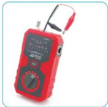
natural_image
Red and black digital multimeter with analog terminals and probe (no visible text or symbols)5. Accessories:
| 1. Emitter 1 piece | 6. Alligator clip 1 piece |
| 2. Receiver 1 piece | 7. RJ45 adaptor cable 1 piece |
| 4. Earphone 1 piece | 8. Instruction manual 1 piece |
| 5. RJ11 adaptor cable 1 piece | 9. Cloth pouch 1 piece |
| 10. 1.5V battery : 4 pcs only for NF-803A / NF-813A | |
| 11. 9V battery : 2 pcs only for NF-803B / NF-813B | |
| 12. Charging adaptor : 1 pcs only for NF-813C | |
6. Function Compare Summary:
| NF-803A | NF-803B | NF-813A | NF-813B | NF-813C | |
| Wire trace | Normal | Normal | Anti-jamming | Anti-jamming | Anti-jamming |
| Wire trace on POE | NO | NO | Yes | Yes | Yes |
| Split test | NO | NO | Yes | Yes | Yes |
| Network wiremap | Yes | Yes | Yes | Yes | Yes |
| Wirmap result | Pin-to-Pin | Pin-to-Pin | In Pair | In Pair | In Pair |
| Port flash | Yes | Yes | Yes | Yes | Yes |
| Telephone line condition test | Yes | Yes | Yes | Yes | Yes |
| Polarity test | Yes | Yes | Yes | Yes | Yes |
| Electric wire contunuity test | Yes | Yes | Yes | Yes | Yes |
| Batteries | 1.5V | 9V | 1.5V | 9V | Li-battery |
Note : The only difference between NF-803A & NF-803B is the battery type : A= 1.5V , B=9V . For NF-813 , C=3.7V built-in Li-battery .

Read the precautions before your operation.
- Keep the tester in right place to avoid hurt with the sharp probe.
● Never put the equipment in the place with much dust, humidity and high temperature (over 40 degree) - Please use the battery according to the specification. Other wise it may result in damage to equipment.
- Please never dismout the equipment arbitrarily. The maintenance and care shall be conducted by professional personnel.
- Please take out the battery in launcher and receiver if the equipment is not used for a long time.
- Never use the equipment to detect power cord with electricity (such as power supply circuit of 220V). Otherwise it may result in damage to equipment and personal injury.
● Never conduct related operation of communication line in thunderstorm weather so as to prevent lightning stroke and impact on personal safety
Diagram of Series Products
NF-868
NF-268
NF-8601
NF-806B
NF-800
NF-820
NF-468L
NF-300
NF-2100
NF-708
NF-905
NF-911