MP-G20-MF - Varrógép JUKI - Ingyenes használati útmutató
Találja meg az eszköz kézikönyvét ingyenesen MP-G20-MF JUKI PDF formátumban.

Felhasználói kérdések a következőről MP-G20-MF JUKI
0 kérdés erről a készülékről. Válaszolj azokra, amiket ismersz, vagy tedd fel a sajátod.
Tegyél fel egy új kérdést erről a készülékről
Töltse le az útmutatót a következőhöz Varrógép PDF formátumban ingyenesen! Találja meg kézikönyvét MP-G20-MF - JUKI és vegye vissza elektronikus eszközét a kezébe. Ezen az oldalon közzé van téve az eszköze használatához szükséges összes dokumentum. MP-G20-MF márka JUKI.
HASZNÁLATI ÚTMUTATÓ MP-G20-MF JUKI
JUKI®
INDUSTRIAL SEWING MACHINE Attachment
MODEL
MP-G20-MF
TECHNICAL MANUAL
Manual Foot Pedal
FOR SAFE USE
Before the installation, operation, and inspection for this product, read the "FOR SAFE USE" and the technical manuals carefully. Also read the other technical manuals, "Sewing Machine Head", "Control Unit" and "Operation Panel" describing some instructions, which are not in this manual, and use the sewing machine properly.
SAFETY INDICATIONS

CAUTION
Indicates that incorrect handling may cause hazardous conditions, resulting in medium or slight personal injury or physical damage. Note that CAUTION level may lead to a serious consequence according to the circumstances. Always follow the instructions of both levels because they are important to personal safety.
CAUTION INDICATIONS
| No. | Caution indication | Description |
| 1 | 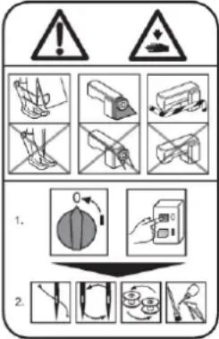 | Precaution for sewing machine operation:Indicates that removing the safety and operating the sewing machine for some other purposes with power-on are prohibited.Please do not operate the sewing machine without protective equipment such as a needle guard, an eye guard, a belt cover or the others.Please turn off the power switch when threading, changing a needle and a bobbin, cleaning, and lubricating. |
| 2 |  | Caution for fingers injury:Indicates a possibility of fingers (hands) injury in a certain condition. |
| 3 | 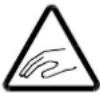 | Caution for squeezing fingers:Indicates a possibility of squeezing fingers in a certain condition. |
1. Setup procedures
1-1. Pedal mechanism
1) Tighten the screws (102) halfway in A and B of the table back side.
2) Hang the long hole point A and B of the link unit (101).
3) Adjust the position of the link unit (101). Tighten the remaining screws (102) and tighten the screw of temporary tightening.
4) Attach the pedal unit (103) and the holder (104) by the screws (105).
5) Put projection part of the holders (104) in the long hole of the support stand. Temporarily fixed the holder (104) by the nuts (106) and the bolts (107).
6) Fix the link unit (101) and the rod link (108) by the bolts (109) and the nuts (110).
7) Fix the rod link (108) and the pedal (111) by the bolt (112) and the nut (110).
8) The pedal unit (103) is sideways moved to the position in which the rod link (108) does not fall to right and left. Fix with the bolts (107).
9) Loosen the D bolts. The pedal is moved back and forth at the position that steps easily. Tighten the D bolts.
10) Tighten the C bolts of the rod link (108).
11) Hang the hook (113) on the E hole. (after assembling the manual mechanism)
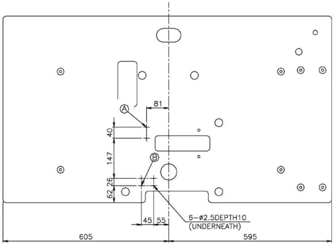
Fig.1 An installation position to the table (the back side)
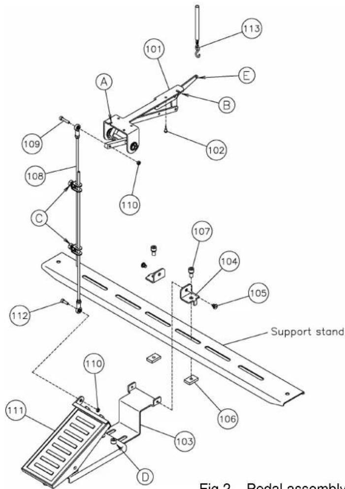
Fig.2 Pedal assembly figure
1-1. Pedal assembly (Parts list)
| Fig | 部品コード | 品名 | Description | 数量 |
| No. | Parts No. | Amt. | ||
| Req. | ||||
| 101 | MH20M0748 | ペダルリンクキコウクミタテ | Pedal link assy | 1 |
| 102 | M90409041 | マルモクネジ 4.5 × 20 | Wood screw D=4.5 L=20 | 6 |
| 103 | MH20M0601 | ペダルトリツケイタ | Pedal adaptor | 1 |
| 104 | MH20M1780 | ホルダ | Holder | 2 |
| 105 | M91690015 | ヒラネジダンツキ | Screw 1/4(40)X4 | 2 |
| 106 | M98606047 | シカクナット | Square Nut | 2 |
| 107 | M98003017 | セフティソケット M8X16 | Safety socket bolt M8X16 | 2 |
| 108 | MH20M0955 | レンケツボウクミタテ | Pitman rod assy | 1 |
| 109 | M95011021 | ロッカクアナツキボルト M5X25 | Socket bolt M5X25 | 1 |
| 110 | M91382045 | ロッカクナット M5 | Nut M5 | 2 |
| 111 | MH20M1748 | ペダルクミタテ | Pedal assy | 1 |
| 112 | M95001021 | ロッカクアナツキボルト M5X16 | Socket bolt M5X16 | 1 |
| 113 | MH20M0376 | クサリセット | Chain set | 1 |
1-2. Manual mechanism
1) Remove the top cover.
2) Remove the J bolts and K bolts, and remove the clamp bracket.
3) Fix the guide pin (201) in the screw hole (401).
4) Remove the existing cover (402). Fix the slide bushing (202) by the bolts (203).
5) Pass the shaft (204) through the hole (403) in the left side, and put the pushing lever (206) in between two collars (205) in the inside of the arm.
6) Fix the bolt (207), the nut (208), and the washer (209) in screw hole (404). Fix the nut (208) so that the protrusive bolt (207) 30mm from arm edge side.
7) Attach the spring (210) on the lever (211), and pass the shaft of the lever (211) through the hole (405). Put the pushing lever (206) on the protrusive shaft of the arm inside, and fix the set sides of the pushing lever (206) by the F screw.
8) Put the rubber plate (213) in the shaft of pressure plate (212). Pass the pressure plate (212) through the hole (402) from the under side, and the guide pin (201) enter the projection part of pressure plate (212).
9) Fix the pushing lever (206) to the pressure plate (212) by the screw (214).
10) Confirm whether the lever (211) and the pressure plate (212) move smoothly, and fix the pushing lever (206) in between two collars (205).
11) Fix the nut (216) so that the protrusive bolt (215) 8mm from the arm upper side of screw hole (407).
12) Hang the spring (217) to the bolt (215). Hang the other side on the G hole.
13) Pass the shaft of lever (211) through the lever (218), and fix it.
14) Temporarily fix the switch (219) to the hole (408) using the screw (220).
15) Fix at the place that the switch does ON of with the lever. (Becomes cause to break when the power to push the switch is strong at this time.)
16) Fix the holder (221) to the hole (409) using the screw (222).
17) Pass the switch cable (219) through from the below of the arm inside, and lead the cable to the solenoid PCB from the hole of the bed. Fix the cable to the holder (221) that doesn't come in contact with another.
18) Insert the switch cable (219) connector to the solenoid PCB.
19) Put the hook (113) in the cushion (223).
20) Hang the hook (113) on the H hole of lever (211).
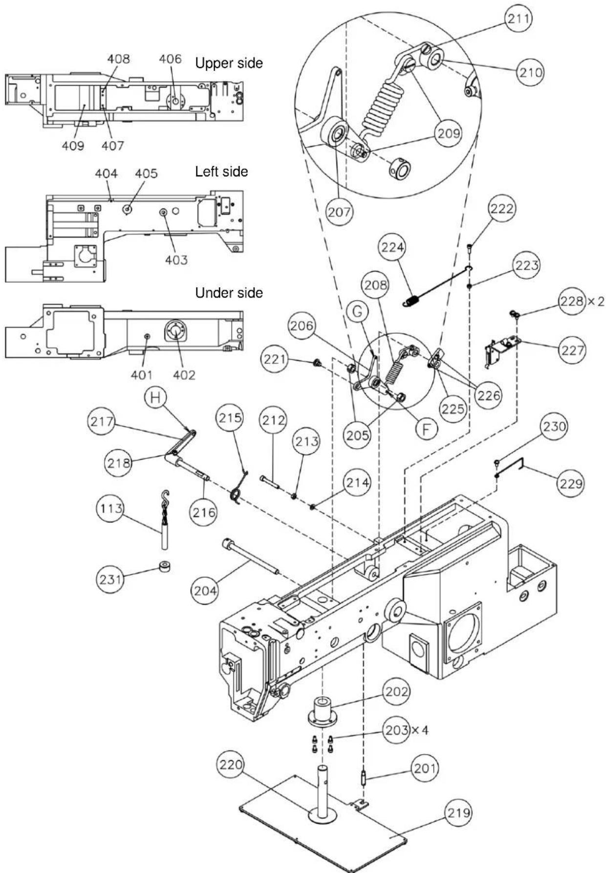
Fig.3 Manual mechanism assembly figure
1-2. Manual mechanism (Parts list)
| Fig | 部品コード | 品名 | Description | 数量 |
| No. | Parts No. | Amt. | ||
| Req. | ||||
| 201 | ME10A0802 | マワリドメ | Stopper | 1 |
| 202 | MH20M0750 | スライドブッシュ | Slide bushing | 1 |
| 203 | M95018021 | ロッカクアナツキボルト M4X8 | Socket bolt M4X8 | 4 |
| 204 | MH20M0454 | レバーシャフトクミタテ | Lever shaft assy | 1 |
| 205 | MH20M0352 | カラークミタテ | Collar assy | 2 |
| 206 | MH20M0950 | レバー F | Lever F | 1 |
| 207 | MH20M0456 | シェルガタハリジョウコロジクウケ | Bearing | 1 |
| 208 | MH20M0700 | バネ | Spring | 1 |
| 209 | M91127015 | ヒラネジダンツキ | Screw 11/64(40)X5 | 2 |
| 210 | MA10A1950 | レバー | Lever | 1 |
| 211 | M91109002 | ヒラネジ | Screw 11/64(40)X7 | 1 |
| 212 | M95008021 | ロッカクアナツキボルト M5X35 | Socket bolt M5X35 | 1 |
| 213 | M91382045 | ロッカクナット M5 | Nut M5 | 1 |
| 214 | M90512050 | コザガネ 5 | Washer 5 | 1 |
| 215 | MA10A0729 | ヒネリバネ | Spring | 1 |
| 216 | MH20M1454 | レバーシャフト | Lever shaft | 1 |
| 217 | MH10A0950 | レバー | Lever | 1 |
| 218 | M95018021 | ロッカクアナツキボルト M4X8 | Socket bolt M4X8 | 1 |
| 219 | MH20M0257 | オサエイタクミタテ | Presser plate assy | 1 |
| 220 | MH20M0416 | カンショウイタ | Rubber cushion | 1 |
| 221 | M91690015 | ヒラネジダンツキ | Screw 1/4(40)X4 | 1 |
| 222 | M94003021 | ロッカクアナツキボルト M4X12 | Socket bolt M4X12 | 1 |
| 223 | M91007045 | ロッカクナット M4 | Nut M4 | 1 |
| 224 | MH20M1700 | バネ | Spring | 1 |
| 225 | MH20M1950 | ケンシュツレバー | Detector lever | 1 |
| 226 | M95018021 | ロッカクアナツキボルト M4X8 | Socket bolt M4X8 | 2 |
| 227 | MH20M0485 | スイッチトリツケイタクミタテ | Switch adaptor assy | 1 |
| 228 | M91071004 | SW-MW ツキ プラマイナベネジ | Screw M4X8 | 2 |
| 229 | MH20M0780 | ホルダー | Holder | 1 |
| 230 | M91054004 | SW-PW ツキ プラマイナベネジ | Screw M3X10 | 1 |
| 231 | MH20M0397 | クッション | Cushion | 1 |
1-3. Clamp mechanism
The left side is similarly assembled with the explanation of the right side.
1) Confirm whether there is the screw hole in the rear of the clamp bracket which removed in step1-2.2). When there is not the screw hole, please process the screw hole at the position of figure 4.
2) The shaft (301) is fixed to the even position of clamp bracket by the two screws (302).
3) Pass the washer (304) and the right lever (305) through the shaft (301), and fixes by the collar (306).
4) Fix the right lever (305) and the cylinder lever (307) by the screw (308) and the nut (309).
5) Fix the post (310) to the cylinder lever (307).
6) Pass the top of spring (311) through the post hole (310). Hang the other side on the L bolt.
7) Fix the clamp bracket with the reverse procedure of step 1-2. 2).
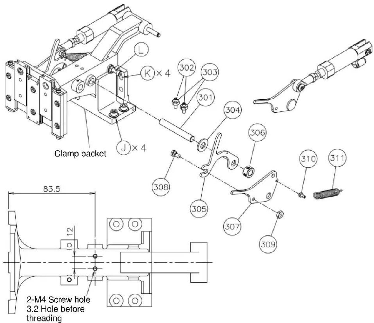
Fig.4 Clamp mechanism assembly figure
1-3. Clamp mechanism (Parts list)
| Fig | 部品コード | 品名 | Description | 数量 |
| No. | Parts No. | Amt. | ||
| Req. | ||||
| 301 | M97019060 | ピン | Shaft | 1 |
| 302 | M91062020 | ロッカクアナツキトメネジ M4X16 | Screw M4X16 | 2 |
| 303 | M91007045 | ロッカクナット M4 | Nut M4 | 2 |
| 304 | M90823050 | ミガキザガネ 8 | Washer 8 | 2 |
| 305 | MH20M0266 | オサエレバー | Pushing lever | 2 |
| 306 | MH20M0352 | カラークミタテ | Collar assy | 2 |
| 307 | MH20A0266 | オサエレバー | Pushing lever | 2 |
| 308 | M91111015 | ヒラネジダンツキ | Screw 11/64(40)X6.2 | 2 |
| 309 | M91104045 | ナット | Nut 11/64(40) | 2 |
| 310 | MH20M0798 | ヒッパリバネヨウボスト | Hook shaft | 2 |
| 311 | MH20A0572 | ツルマキバネ | Spring | 2 |
Note: Fig No.307 and No.311 are not included in this package. Please use existing parts which have standard PLK-G2010R.
2. Operation
(1) The holder plate (213) comes down when the pedal (111) is stepped on, and the clamp frame comes down.
(2) If the position of sewing thing is decided, the work clamp is turned ON when the pedal (111) is stepped more. Quantity of stepping forward changes by adjusting lever (220).
(3) Press the [Black] side on the foot switch to comes up the clamp frame.
(4) Press the [Gray] side on the foot switch to rotate the sewing machine and start stitching.
(5) When stitching is completed, the sewing machine will automatically return to home, and the clamp frame will comes up.