DADG-AK-G8-6-40 - Kategooriata Festo - Tasuta kasutusjuhend
Leidke seadme juhend tasuta DADG-AK-G8-6-40 Festo PDF-formaadis.

Kasutajate küsimused teemal DADG-AK-G8-6-40 Festo
0 küsimus selle seadme kohta. Vastake nendele, mida teate, või esitage oma.
Esita uus küsimus selle seadme kohta
Laadige alla juhend oma Kategooriata PDF-formaadis tasuta! Leidke oma juhend DADG-AK-G8-6-40 - Festo ja võtke oma elektrooniline seade uuesti kätte. Sellel lehel on avaldatud kõik teie seadme kasutamiseks vajalikud dokumendid. DADG-AK-G8-6-40 kaubamärgi Festo.
KASUTUSJUHEND DADG-AK-G8-6-40 Festo
DADG-AK-G8
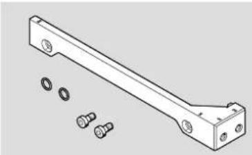
Connection set
natural_image
Technical line drawing of a mechanical bracket with bolt holes and multiple bolts (no text or symbols)FESTO
Festo SE & Co. KG
Ruiter Straße 82
73734 Esslingen
Deutschland
+49 711 347-0
www.festo.com
Assembly instructions
8157118
2021-08
[8157120]

8157118
Translation of the original instructions
© 2021 all rights reserved to Festo SE & Co. KG
1 Applicable documents
□1
All available documents for the product → www.festo.com/sp.
Document Product Table of contents
| Operating instructions Mini slide | DGST |
Tab. 1: Applicable documents
2 Safety
2.1 Safety instructions
-Only mount the product on components that are in a condition to be safely operated.
-Observe further applicable documents.
- Observe tightening torques. Unless otherwise specified, the tolerance is ± 10%.
2.2 Intended use
Connection of compressed air lines axially at the back of the mini slide DGST.
3 Additional information
- Contact the regional Festo contact if you have technical problems → www.festo.com.
- Accessories and spare parts → www.festo.com/catalogue.
4 Product Range Overview
4.1 Scope of delivery
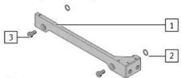
1 Air through-guide (1x)
2 O-ring (2x)
3 Socket head screw (2x)
Fig.1
4.2 Not in scope of delivery
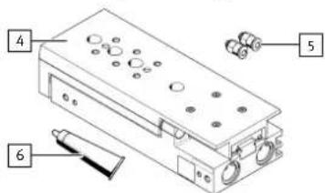
4 Mini slide (1x) DGST
5 Fitting (2x)
6 Grease (1x)
e.g. LUB-KB1
Fig.2
5 Assembly
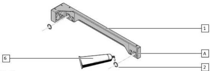
Fig.3
- Lightly grease the O-rings 2 with the grease 6 to facilitate assembly.
- Position the O-rings 2 in the slots [A] of the air through-guide 1.
i
The nominal tightening torques are printed on the air through-guide.
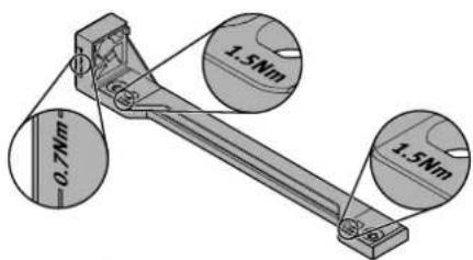
Fig. 4: Example: DADG-AK-G8-16
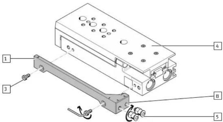
Fig.5
| DADG-AK-G8 DGST- | ||||||||
| 6 8 10 | 12 16 20 25 | |||||||
| 3 | Screw M3x5 M3x8 M4x8 | M5x12 | M6x12 | |||||
| [Nm] | 1.0 1.2 1.5 | 3.0 5.0 | ||||||
| [B] | Air connection thread | M5 | G1⁄2 | |||||
| [Nm] | 0.7 | 3.0 | ||||||
Tab. 2: Screw size, tightening torques and air connection thread
- Place the air through-guide 1 on the mini slide 4.
- Fasten the air through-guide 1 with the screws 3 to the mini slide 4.
- Mount the desired fittings 5 on the air connection threads [B].
i
Use of one-way flow control valves GRLA on the air connection threads [B]
One-way flow control valves GRLA may restrict the access [C] to the adjustment of end position on the DGST.
- Adjust the external end position before mounting the one-way flow control valves [D].
- Rotate the one-way flow control valves [D] so the access remains clear.
![Festo DADG-AK-G8-6-40 - Use of one-way flow control valves GRLA on the air connection threads [B] - 1](/content/2026/05/1095194/images/1b898ab0ca3f05d6c9bbcfcfbc57dab5dc3204ec5ca24cd91310b37f72b90e88.jpg)
![Festo DADG-AK-G8-6-40 - Use of one-way flow control valves GRLA on the air connection threads [B] - 2](/content/2026/05/1095194/images/fe263b0d2839b3a63a0221963cbddf64ad260b8db4381f0f86a1b508ebf45409.jpg)
Fig.6