
MIB T5142 - Arvutikorpus GIGABYTE - Tasuta kasutusjuhend
Leidke seadme juhend tasuta MIB T5142 GIGABYTE PDF-formaadis.

Kasutajate küsimused teemal MIB T5142 GIGABYTE
0 küsimus selle seadme kohta. Vastake nendele, mida teate, või esitage oma.
Esita uus küsimus selle seadme kohta
Laadige alla juhend oma Arvutikorpus PDF-formaadis tasuta! Leidke oma juhend MIB T5142 - GIGABYTE ja võtke oma elektrooniline seade uuesti kätte. Sellel lehel on avaldatud kõik teie seadme kasutamiseks vajalikud dokumendid. MIB T5142 kaubamärgi GIGABYTE.
KASUTUSJUHEND MIB T5142 GIGABYTE
GIGABYTE™
Components Introduction

Product is not warranted if the products is modified, altered or repaired without authorization by GIGABYTE. Specifications and pictures are to change without notice.
Components Introduction
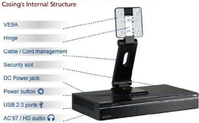
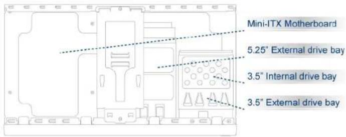
Casing's Internal Structure
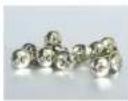
Accessory Box
MIB T5140 / MIB T5142
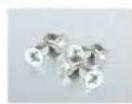
HDD securing screw x 6
Motherboard / ODD /
Foppy securing screw x 12
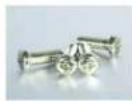
LCD Monitor securing screw x 4
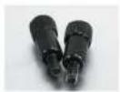
VESA thumb screw x 2
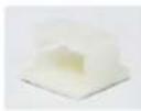
Wire clamp x 1
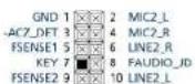
Installation of Front Multi-Media I/O ports
USB 2.0 ports & AC'97 / HD audio
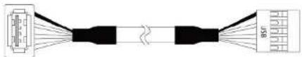
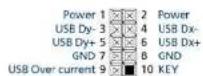

Be sure that different motherboards may have different installation areas and specifications, screw holes and connectors. For detailed instructions, please refer to the motherboard user manual supplied by the motherboard manufacturer.
STEP 1
Remove top cover
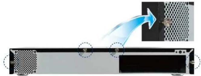
natural_image
Diagram showing a device's internal structure with a blue arrow indicating flow, no text or symbols present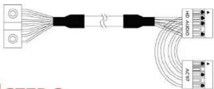

STEP 2
Installation of Motherboard
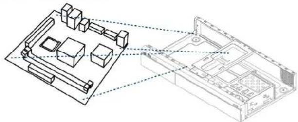
natural_image
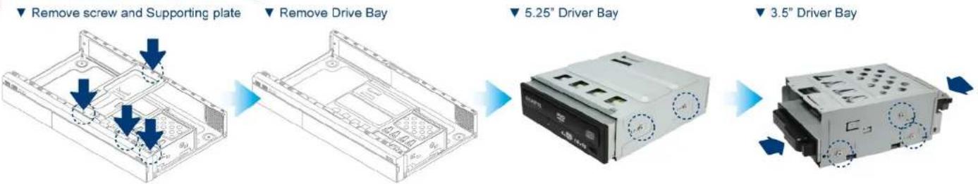
Technical line drawing of a computer motherboard with connected components (no text or symbols)STEP 3
Installation of 5.25" & 3.5" Driver Bay
STEP 4
Installation of LCD Monitor to CASE

Connect hinge onto chassis and mount monitor before adjusting the angle of the hinge.
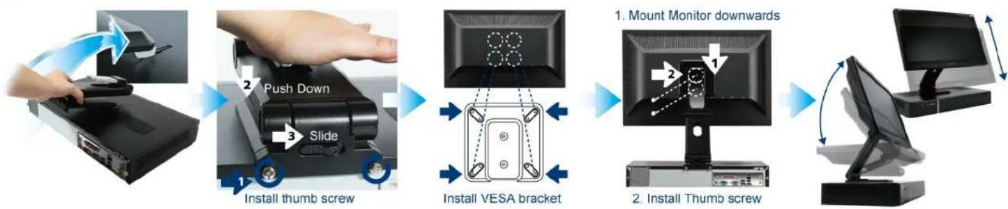
flowchart
graph LR
    A["User Hand"] --> B["Push Down"]
    B --> C["Slide"]
    C --> D["Install thumb screw"]
    D --> E["Install VESA bracket"]
    E --> F["Mount Monitor downwards"]
    F --> G["Install Thumb screw"]
    G --> H["Computer monitor with scroll arrow"]


Kaubamärk : GIGABYTE
Mudel : MIB T5142
Kategooria : Arvutikorpus