
CEA525T - Kaitselüliti HAGER - Tasuta kasutusjuhend
Leidke seadme juhend tasuta CEA525T HAGER PDF-formaadis.

Kasutajate küsimused teemal CEA525T HAGER
0 küsimus selle seadme kohta. Vastake nendele, mida teate, või esitage oma.
Esita uus küsimus selle seadme kohta
Laadige alla juhend oma Kaitselüliti PDF-formaadis tasuta! Leidke oma juhend CEA525T - HAGER ja võtke oma elektrooniline seade uuesti kätte. Sellel lehel on avaldatud kõik teie seadme kasutamiseks vajalikud dokumendid. CEA525T kaubamärgi HAGER.
KASUTUSJUHEND CEA525T HAGER

natural_image
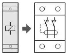
Line drawing of a dual electrical switchgear (no text or symbols)Safety switch (RCCB's) 25 - 100A

GB For the tripping times verification tests, in an electrical installation, Hager certifies that the RCDs, of the Hager brand, conforming to standards EN 61008-2-1, EN 61009-2-1, trip under a current of 5*IΔn in accordance with the times imposed in table 41.1 of standard DIN VDE 0100-410 (VDE 0100-410) 2018-10.

Safety instructions
The installation and mounting of electrical appliances must only be performed by qualified electricians, in compliance with installation standards and in accordance with the guidelines, provisions and safety and accident prevention regulations in force in the country concerned.
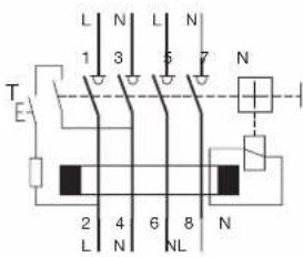
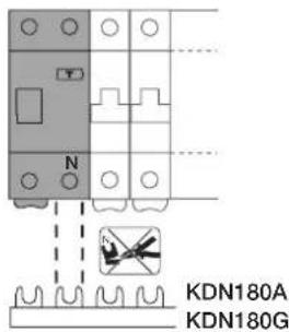
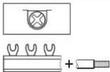
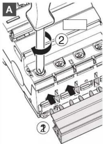
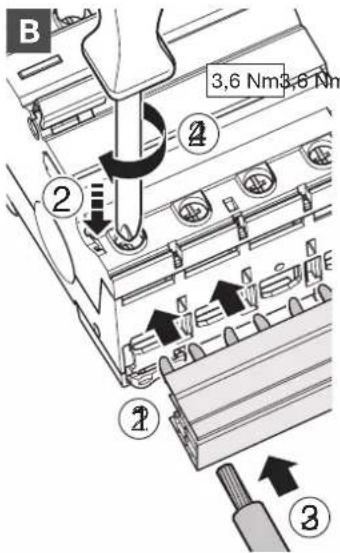
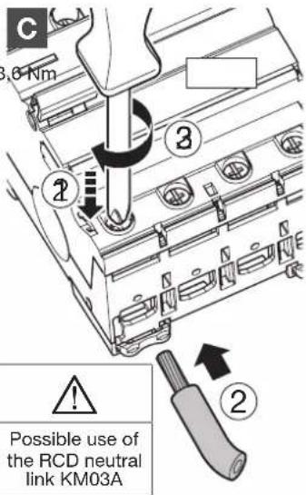
Electrical connection 2 pole.
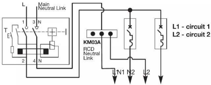
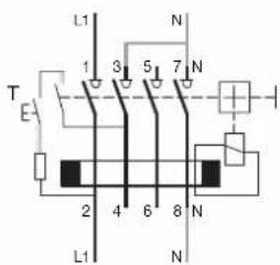
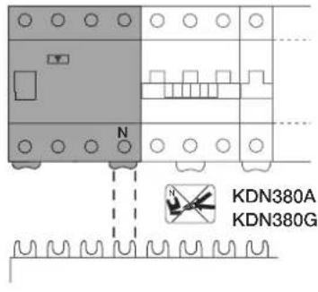
For an RCD where two or three circuits are to be protected, the Hager neutral link KM03A may be connected to the outgoing N terminal for the convenient splitting of the neutrals.
Please note the following
1 - The current rating per pole of the RCCB must not be exceeded by the maximum demand of the protected circuits.
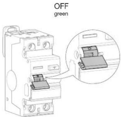
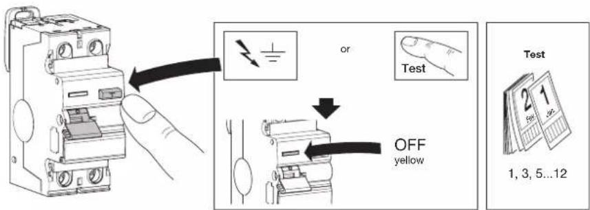
2 - If RCCB trips OFF after installation, locate and repair faulty appliances (cumulative leakage from a number of appliances may exceed the RCCB tripping current, causing RCCB to trip OFF).
3 - The "main neutral" and "main earth" should be checked to ensure good connection.
4 - If RCCB trips intermittently will not reset, or test button will not work, check for low insulation resistance between neutral & earth wiring.
5 - RCCB may be fed in any position:
LOAD and LINE circuits may be connected top or bottom.
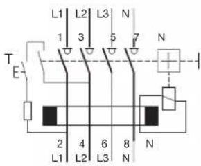
Electrical connection for P+N or for three phase only.
Three phase & neutral use or Three phase use
Single phase use Two circuits
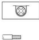
One circuit
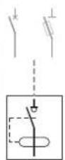
Position contact indication.
Earth leakage fault indication.
Single phase connection.
Three phase connection.
A
B
C
Auxiliary possibilities.
MZ201
MZ202
MZ203
MZ204
MZ205
MZ206
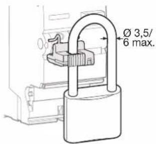
Locking device for handle MZN175.

Protection against dust
In case of work activities nearby, make sure that the electrical installation is protected against dust if the enclosure is not IP5x.


Kaubamärk : HAGER
Mudel : CEA525T
Kategooria : Kaitselüliti