
JPD2400S25DW - Lüliti HAGER - Tasuta kasutusjuhend
Leidke seadme juhend tasuta JPD2400S25DW HAGER PDF-formaadis.

Kasutajate küsimused teemal JPD2400S25DW HAGER
0 küsimus selle seadme kohta. Vastake nendele, mida teate, või esitage oma.
Esita uus küsimus selle seadme kohta
Laadige alla juhend oma Lüliti PDF-formaadis tasuta! Leidke oma juhend JPD2400S25DW - HAGER ja võtke oma elektrooniline seade uuesti kätte. Sellel lehel on avaldatud kõik teie seadme kasutamiseks vajalikud dokumendid. JPD2400S25DW kaubamärgi HAGER.
KASUTUSJUHEND JPD2400S25DW HAGER
natural_image
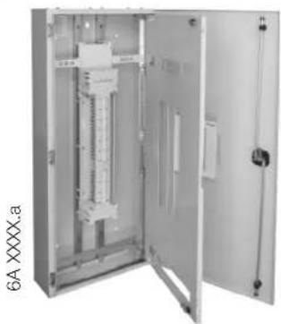
Interior view of an open electrical control cabinet (no visible text or symbols)performa 2 apex & apex PLUS
Note: Only registered Electrical Contractors are to do any installation to panelboards
The electrical contractor is to ensure that the panelboard meets site specific requirements. Final installation is to meet all rules as described in AS/NZS 3000:2007.
Switchboard Mounting
The electrical contractor must ensure that the support structure or wall is adequate to support the weight of the panelboard. All cables entering or exiting the switchboard are to be via a gland or sealed as required. All panelboards have lockable doors suitable for restricted areas as per AS/NZS 3439.3:2002.
Switchgear mounting in Panelboard
The electrical contractor is to ascertain that all installed devices are suitable to meet the appropriate fault current ratings required. The chassis on this panel board is suitable for Hager 10kA type of MCBs and RCBOs and was designed to suit only Hager MCBs. Hager's recommends fitting only Hager approved switchgear otherwise this may void warranty. If the fault level at the switchboard is greater than the MCB fault rating, they must be backed up by current limiting fuses or current limiting circuit breakers. For backup protection levels refer to Hager. Devices are to be mounted with the DIN clip toward the centre of the enclosure. Transportation may cause terminations, mechanical supports and other connections to become loose. The electrical contractor is to ensure all these connections are tightened prior to any energisation.
Final overview prior to Energisation
Review alignment of all devices and ensure there has been no damage during final terminations. The panelboard is to be cleaned and vacuumed from filings and other foreign objects after final terminations are completed.
Panelboard
Board mounting
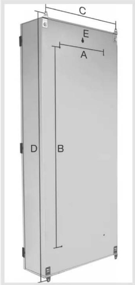
| Dimensions | A B C | D | ||
| apex 24 pole 350 500 | 560 | 820 | ||
| apex 36 pole 350 700 | 560 | 1020 | ||
| apex 48 pole 350 900 | 560 | 1020 | ||
| apex 60 pole 350 900 | 560 | 1220 | ||
| apex 72 pole 350 1100 | 560 | 1220 | ||
| apex 96 pole 350 1300 | 560 | 1420 | ||
| apex + 24 pole 350 700 | 560 | 1020 | ||
| apex + 36 pole 350 900 | 560 | 1220 | ||
| apex + 48 pole 350 900 | 560 | 1220 | ||
| apex + 60 pole 350 1100 | 560 | 1420 | ||
| apex + 72 pole 350 1100 | 560 | 1420 | ||
| apex + 96 pole 350 1300 | 560 | 1620 | ||
| apex extension 350 150 | 560 | 420 |
User Instructions
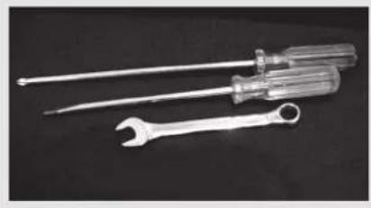
Tools needed
natural_image
Two types of screwdrivers displayed on a black surface, one with a wrench and the other with a flat screwdriver (no text or symbols visible)2 Phillips head screwdriver
Flat Blade screwdriver
8mm & 13mm spanner
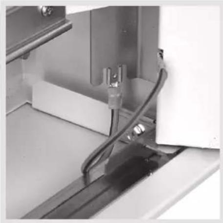
Earth wire fitted
natural_image
Close-up of a mechanical or electrical component with visible wiring and mounting brackets (no text or symbols)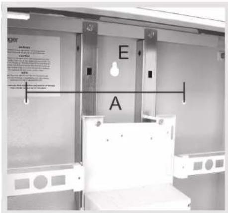
E = Central keyhole fixing point
Earth and Neutral links
| Neutral bars Integrated | neutral bars |
| Neutral bar size (mm) 12x9 | |
| Split neutral As standard | |
| Earth bars Earth bars both sides | |
| Earth bar size (mm) 12x9 | |
| Earth and neutral bar tunnels | Single screw tunnel 7mm (up to 25mm^2 cable) solid and stranded conductors ^1 |
| Earth and neutral bar connection | Single stud (M6 = 2.5Nm) |
| Earth and neutral bar rating | 250A |
1 Copper strands must be firmly twisted together using a tool i.e. pliers.
Door removal
natural_image
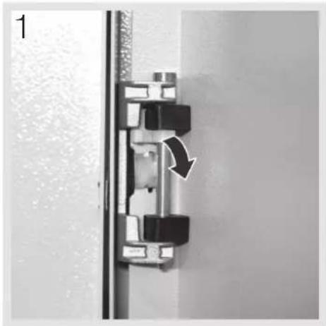
Mechanical assembly diagram showing a piston-like component with a rotating arrow, no text or symbols presentEscutcheon removal
Mounting a safety pole filler
natural_image
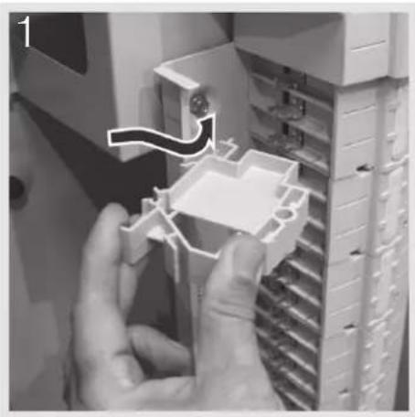
Close-up of hands installing or adjusting a plastic component into a rack cabinet (no visible text or symbols)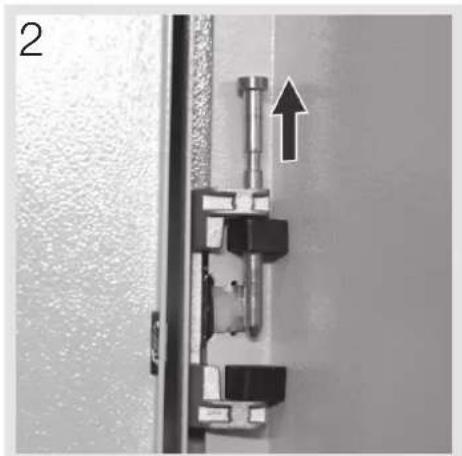
natural_image
Close-up of a mechanical assembly with a vertical rod and mounting bracket, showing a directional arrow (no text or symbols)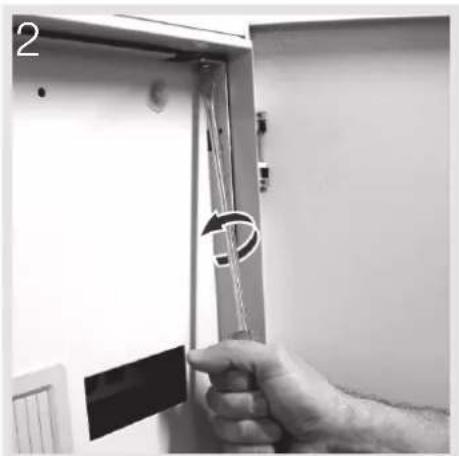
natural_image
Hand holding a vertical panel with a circular arrow indicating rotation (no text or symbols visible)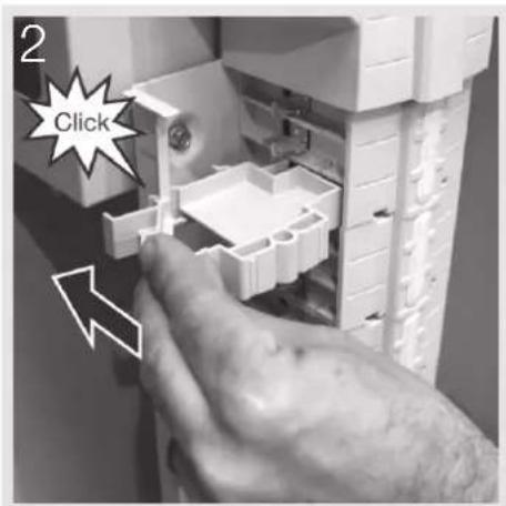
Note: for door reversal, the apex lock position is universal.


Kaubamärk : HAGER
Mudel : JPD2400S25DW
Kategooria : Lüliti