H-906SA - Järelevalvekaamera Joblotron - Tasuta kasutusjuhend
Leidke seadme juhend tasuta H-906SA Joblotron PDF-formaadis.

Kasutajate küsimused teemal H-906SA Joblotron
0 küsimus selle seadme kohta. Vastake nendele, mida teate, või esitage oma.
Esita uus küsimus selle seadme kohta
Laadige alla juhend oma Järelevalvekaamera PDF-formaadis tasuta! Leidke oma juhend H-906SA - Joblotron ja võtke oma elektrooniline seade uuesti kätte. Sellel lehel on avaldatud kõik teie seadme kasutamiseks vajalikud dokumendid. H-906SA kaubamärgi Joblotron.
KASUTUSJUHEND H-906SA Joblotron
WORKING MODES OF THE H-906SA
Armed (AWAY) In this mode, all connected detectors can trigger an alarm. Detectors in the Delay Zone will only trigger an alarm after the entrance delay.
Disarmed (HOME) In this mode, the system will not react to movement of people in the house. Detectors in the 24Hr zone can still trigger an alarm.
Alarm If alarm is triggered, the control panel will switch on the siren and other installed optional devices (telephone dialer, outdoor siren etc.). The alarm will reset automatically after a predetermined period. The alarm can be stopped by the key switch or by external controller if installed.
Service this mode can be selected only by using the key. You can service the system in this mode (set & test sensors, set control panel etc.). No alarm can be triggered while in this mode.
HOW TO OPERATE THE SYSTEM
The system is normally controlled by the key or by an external controller (digital keypad, remote control etc.). If an external controller is installed, the control panel should be switched to the STAND BY position in order to be able to accept the external controller instructions.
ARMING
To arm the system, switch the key to the ARM position (or use external controller if installed). The ARM LED will start blinking (and the siren will sound once if the chirp function is enabled). A slow blinking of the ARM LED indicates that the exit delay is activated. During the exit delay, any sensor in the Delay zone can be activated without triggering the alarm. After the exit delay, the ARM LED lights permanently and all zones are armed.
Note: No animal can stay in an area covered by motion detectors.
DISARMING
To disarm the system, switch the key to the STAND BY position (or use external controller if installed). The ARM LED will switch off (and the siren will sound twice if the chirp function is enabled). If you trigger any detector in the Delay zone before disarming, the system will provide an entrance delay. The entrance delay is indicated by the fast blinking of the ARM LED and sounding of the optional chime buzzer, if installed.
Note: If the disarming is confirmed by three chirps instead of two, check the control panel's LEDs for important system information (alarm memory).
Zone location
| Zone: | ||
| Delay | ||
| Instant | ||
| Instant | ||
| 24 hr. L4 | ||
| Exit/Entry delay: Alarm duration: | ||
| If troubles, call your installer phone: | ||

JABLOTRON
JASIKRON
Poc Stinkou 3.1
406 01 | ablone: nad Nispu
Czech Republic
tel: 470-428-346911, lnx: 470-428-313-83
export@oblotron.cz
L1 L2 L3
Alarm Control panel H-906SA
2/4
MCV51902
Alarm Control panel H-906SA
Description
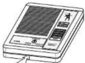
The Hestia H-906SA is a wire operated home alarm system designed for easy installation and use. The control panel provides four protection zones (24h, delay and two instant inputs). An assortment of detectors can be connected to the control panel to suit your needs. Refer to the Jablotron catalog for more details on optional detectors.
The control panel can be operated with the built-in key switch, or with an external controller (digital keypad, remote control, hidden switch etc.). The H-906SA outputs can be connected to an external siren (SA-105,SA-107), outdoor siren (OS-300), telephone dialer (TD-101, TD110) or a wireless pager (PG 2) to alert of an alarm. Pre-alarm and Chirp signals are also available on H-906SA outputs.
SPECIFICATIONS
power required: 15VAC/10VA (DE-20-15 adapter can be used)
backup battery required: 12V, 1.3Ah (SA-214/1.3)
stand-by consumption: 30mA
back-up power output: 12V, max. 400mA
four zones: 24h, delay an two instant, all N.C. inputs
external ARM control input: pulse N.O. input
output rely: over-switching contact, 1A at 60 V
internal siren: 118 dB/1m
external siren output: 0.3A at 12 V
backup siren outou!: +BS
arm output: 0.2A to GND
chime output: 0.2A to GND
CE
Complies with the essential requirements of: 89/336/EC EMC Directive - Protection concerning electromagnetic compatibility when is used for its intended purpose. Original of the conformity assessment can be found at the web page www.jablotron.cz, section Technical support.
Note: Dispose of batteries safely depending on the type of the batteries and local regulation. Although this product does not contain any harmful materials we suggest you to return the product to the dealer or directly to the producer after usage.
FRONT PANEL
POWER (Green LED) continuously lit indicates that the power supply is properly functioning. A blinking
led means that the system is powered only by the back up battery. If this LED is off, the system has no A.C. power and the back-up battery is discharged.
ARM
(Yellow LED) if this LED is off, the system is disarmed. If it is slowly blinking, it indicates an Exit delay. A continuously lit LED indicates that the system is fully armed. A rapidly blinking LED indicates an Entrance delay.
ZONE STATUS LEDs: (DELAY, INSTANT, INSTANT, 24hr.). When in the normal operating mode, a lit LED indicates a triggered input. A slow blinking zone LED indicates that there is some alarm memory information. It can be reset by rearming. A rapidly blinking zone means an alarm condition on the control panel.
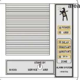
CONTROL KEY SWITCH has three positions: SERVICE - you can service the system in this position (set control panel, test sensors, etc.).
Alarm Control panel H-906SA
3/4
MCV51902
No alarm can be triggered in this position. STAND BY - is the normal operating position (only 24hr zone is armed). System in STAND BY can be controlled by an external device if connected. ARM - this position can be used for manual arming of the system by the key.
INSTALLATION
The Control panel should be fixed to a wall using two screws. Open the front panel by pressing the lock located on the bottom of the H-906SA. Place a narrow screwdriver into the small slot and press the plastic tab inside. Remove the panel slowly and disconnect the cable from the back panel by pulling the connectors from the rear board. Find a suitable location for the control panel. Be sure that the surface of the wall is level. There are two slots for screws on the back side of the rear panel. To mount the panel, first partially screw in the top screw, leaving part of the head sticking out. Slide the screw head through the round hole in the upper half of the back side of the rear panel. Once the screw is in, slide the plastic housing down so that screw slides to the middle of the slot. Now mark the position of the lower screw and again take down the rear panel. Make a hole in the wall for the second screw.
Now replace the rear panel on the wall again and place all the cables through the hole for cables in the rear panel. When all wiring is finished, screw in the top and bottom screws tightly.
Wiring
ACCU. the cable with two female flat connectors (red + and black -) are ready to connect to a back-up battery 12V, 1.3Ah (suitable model SA-214/1.3). In normal operating mode the control panel charges the battery. The battery input is protected by a FU3 (1.6A) fuse. Do not connect the battery before the installation is finished!
15 VAC input - these two terminals are for the A.C. power supply connection. Use a transformer with 15VAC output (min. 10VA), or you can use the Jablotron DE-20-15 adapter. This Input is protected by a FU1 (1.6A) fuse. Do not switch the power on before the installation is finished!
+/- 12V back up voltage output for optional devices (motion detectors, telephone dialers etc.). The maximum current consumption is 400mA. The +12V output is protected by a FU2 (1.6A) fuse.
BS this terminal is for connection with an outdoor back-up siren (OS-300). There is a positive potential supplied by this terminal when there is no alarm condition.
C,NO,NC over switching dry contact of alarm output relay, max. load 1A/60V
+/- SIR external siren output, 12V/max. 0.3A (suitable model SA-105).
CHM chime output is switched to the GND (max. 0.2A/12V) during the entry delay. It can be used for an external pre-alarm buzzer. Connect BUZ-12 buzzer to CHM and +12V terminals when a pre-alarm function desired. The buzzer should be installed close to the entrance, and away from the control panel. The chime output also provides chirp signal as audible confirmation of arming and disarming.
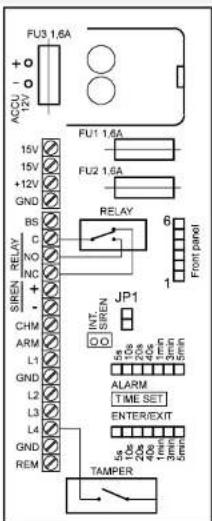
ARM output is switched to the GND while the control panel is armed (max. 0.2A/12V). It can be used for external indication of control panel status.
Alarm Control panel H-906SA
2/4 MCV51902 Alarm Control panel H-906SA 3/4 MCV51902
L1 to L4 and GND terminals = Zone inputs: All zone inputs are N.C. (Normally Closed) circuits. Each input must be closed to one of the GND terminals. An input will be triggered if a normally closed contact (or any of contacts wired in series) is opened. The 24hr zone can also be triggered by the control panel's built in tamper switch. (L1=Delay, L2=Instant, L3=Instant, L4=24hr.)
REM external arm control input. This input works as N.O. (Normally Open) circuit for external arming and disarming. If you close this input to the GND for a moment, the control panel will arm or disarm (depends on current status). Any controller with pulse output can be used (hidden push-button, wireless remote control UC-216, digital keypad KB-1051, 2051 etc.). If you need more external controllers, connect their NO pulse outputs parallel. If you do not use any external arm control, do not connect the REM terminal.
Note: To accept external control instructions, the H-906 panel must be switched into STAND BY position. See the wiring example diagrams for more details.
Procedure for Turning on the Power:
First, check all the connections you have made. Then, connect the A.C. power supply and the green LED on the board should light up. Then connect and place the back up battery (12V, 1.3Ah) to the battery compartment (the red terminal = positive pole). Fix the battery to the adhesive tape inside the housing.
Prepare the front panel of the H-906SA and check that the lock on front panel is switched to the SERVICE position. Connect the cable to the DISPLAY connector on the PCB. To close the control panel housing, put the top side of the front panel over the back panel and then push the bottom side of the front panel against the wall (the tab will click). The POWER LED should light permanently and the control panel will be in Service Mode. You can test the function of all connected detectors now (zone LEDs indicate if an input is triggered). In the end switch the key to the STAND BY position and the H-906 system is installed.
Control panel setting
Your system functions were preset at the factory to facilitate installation. However, you can easily modify some functions. When you want to make a control panel setting or some modification of the system, you must first switch the control panel to the SERVICE mode. Then open the front panel and disconnect the front panel cable. The A.C. adapter should remain plugged in and the back up battery should remain connected as well.
ENTRY/EXIT delay setting the duration of this delay is preset for 20 seconds. To change the duration of this delay, change the position of the ENTER/EXIT jumper on the board (see the scale printed on the board). If you leave the jumper disconnected, the minimum delay of 5 seconds will be set.
ALARM duration setting the duration of this delay is preset for 3 minutes. To change the duration, change the position of the ALARM jumper on the board (see the scale printed on the board). If you leave the jumper disconnected, the minimum duration of 5 seconds will be set.
CHIRP if you close the JP1 link on the board, arming and disarming will be audibly confirmed by the siren (one chirp for arming, two chirps for disarming and three chirps for disarming with alarm memory on the display).
Note: Chirp signal is also provided on CHIME output (no matter what position of JP1 link). When all settings are finished, replace the front panel (the key must be in SERVICE position).