JA-80IR - Järelevalvekaamera Joblotron - Tasuta kasutusjuhend
Leidke seadme juhend tasuta JA-80IR Joblotron PDF-formaadis.

Kasutajate küsimused teemal JA-80IR Joblotron
0 küsimus selle seadme kohta. Vastake nendele, mida teate, või esitage oma.
Esita uus küsimus selle seadme kohta
Laadige alla juhend oma Järelevalvekaamera PDF-formaadis tasuta! Leidke oma juhend JA-80IR - Joblotron ja võtke oma elektrooniline seade uuesti kätte. Sellel lehel on avaldatud kõik teie seadme kasutamiseks vajalikud dokumendid. JA-80IR kaubamärgi Joblotron.
KASUTUSJUHEND JA-80IR Joblotron
JA-80IR wireless optical barrier
The JA-80IR optical barrier is designed for the indication of a breach into a protected area by crossing the IR line between the transmitter and the receiver. The barrier is a product by Optex supplemented with transmitters compatible with OASiS systems, this being both in the transmitting and receiving part of the barrier. The device power supply is ensured by high-capacity lithium batteries. The signal indicating that a transmitter and receiver battery is low is transmitted to the control panel. The barrier occupies two enrollment positions in the system. Barrier activation is reported by the receiving part of the barrier (the position where its radio transmitter is enrolled in the system). Both parts of the barrier can send a tamper signal to the control panel. The transmitters regularly perform automatic tests and report their status to the system.
Barrier installation
The following instructions should be observed when selecting a place for barrier installation:
- Both units must be installed onto a stationary construction (e.g. a wall or a thick post) at the same height and should face each other.
- The area between the barrier units must not be blocked by any bushes or tall grass.
• There can be up to a 60 m distance between the units. - The receiver unit must not be affected by direct sunlight.
- The units should be installed 0.7 – 1 m above the ground.
- If the IR beam is parallel to a wall, there must be at least a 1 m distance between the beam and the wall.
- If multiple barriers are used, their IR beams should not interfere with each other.
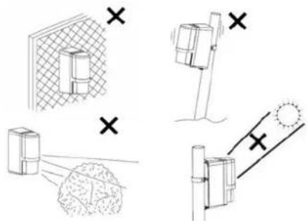
Fig. 1 Undesirable locations
Installation steps:
The transmitting unit (marked TRANSMITER) and the receiving unit (marked RECEIVER) are of identical mechanical construction.
Cover Optical part Rear part Base
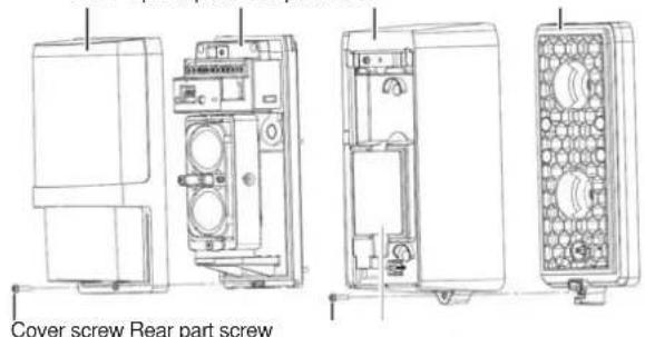
Fig 2 Barrier parts (identical for transmitter and receiver)
- Unscrew the rear part screws and remove the unit bases.
- Install the bases onto the selected places, either directly on a surface (wall) – in such a case punch two holes through the base – or onto a post 43 – 48 mm in diameter using the supplied clips and clips.
- When installing the base, always check whether the rubber tamper contact pin is functional.
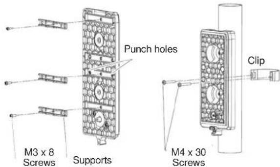
Fig. 3 Preparation for installation onto a post
- Enroll the transmitters into the system – see below.
- Perform optical adjustment and unit transmitter setting.
- Screw the upper covers back in and test the barrier functioning.
Enrolling the barrier transmitters into the system
The transmitters for wireless communication are located in the rear part underneath the optical section. The barrier occupies two enrollment positions in the system. Barrier activation is reported by the receiving part of the barrier (the position where its radio transmitter is enrolled in the system). Both parts of the barrier can send a tamper signal to the control panel.
Always use two SAFT LSH20 lithium batteries to power the barriers (they are included in the package). The batteries should be inserted very carefully to avoid damage to the transmitter wiring. When the first battery has been installed, the transmitter sends a signal which enrolls it to the control panel (the control panel must be in enrollment mode at that time – see the manual). Use switch no. 2 to set the required system reaction to movement (ON = instant or OFF = delayed). Switch no. 1 should be left in the OFF position
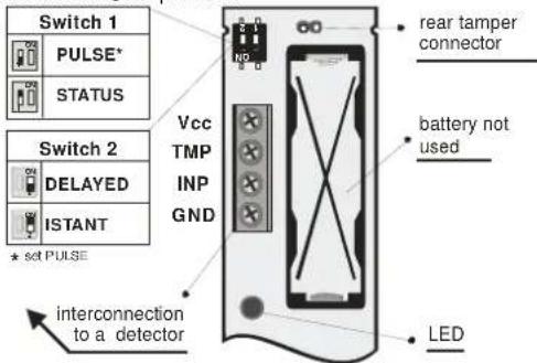
Fig 4 Radio transmitter (identical for transmitter and receiver)
Setting up the optical part of the barrier
The optical part of the barrier must be adjusted so that the optical parts facing each other are physically aligned. Both units are equipped with adjusting elements for the adjustment of direction and a view-finder for precise adjustment. The unit opposite the one you want to adjust must be in the centre of the aiming cross and the cross must be in the centre of the view-finder.
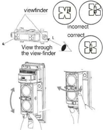
Fig. 5 Setting up the optical part
When the setting is complete, it is followed by adjustment of the receiver unit:
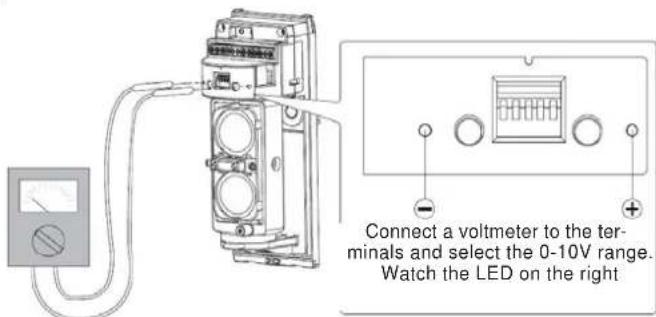
Fig. 6 setting up using a multimeter
A permanently lit LED on the right indicates that the beam has been interrupted (or wrongly adjusted). The better the beam reception, the longer the breaks between the LED flashes. When the LED stops flashing, continue looking for the ideal position indicated by the highest voltage measured on the voltmeter.
Setting up the electronic part of the barrier
Both units are equipped with setting switches. The switch located on the side of the units (on the optical part) allows barrier beam modulation frequency adjustment from 1 to 4. This setting is useful only for a combination of multiple JA-80IR barriers where a problem with interference might appear. For more information see the original user.
There is a DIP switch with five switches. The first two positions are used to set the reaction time to an interruption of the beam. The shorter the time, the more precise the interruption detection, but also the greater the susceptibility to false alarms during worsened optical conditions (snow, fog, ...)
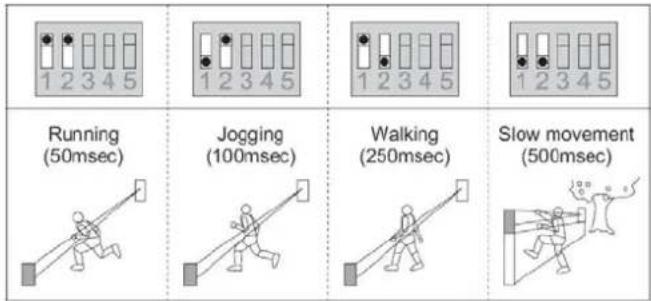
Fig. 7 Reaction time setting
It is possible to set a 2-minute sleep time after an alarm (beam interruption) in order to save batteries. This setting is done by switching switch no. 3 (receiver unit), or no. 1 (transmitter unit) to the ON position. Switches 4 and 5 (receiver unit), or better 2 and 3 (transmitter unit) are set as a default and you should leave them in the OFF position for the correct functioning of the device.
Operation testing
The LEDs on the barrier have the following indication functions
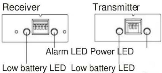
Fig 8 LEDs on the units
The signal battery low LEDs flash when the batteries in the unit are low. Both batteries (SAFT LSH20 lithium batteries) should always be replaced at the same time.
The alarm LED flashes during beam blocking.
The power LED flashes when the battery in the transmitting unit is OK.
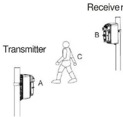
Fig. 9 Barrier function test
Perform a barrier test in three places (A B and C). The setting is completed only if the barrier reacts successfully in all three positions. You should also check the signal transmission to the system control
panel. Only then is it possible to put back the unit covers and secure them.
Checking the status of and replacing batteries
The detector checks battery status automatically and if the batteries are running low, it informs the system. The detector remains fully functional. The batteries should be replaced as soon as possible (within 1 week). Use SAFT LSH20 batteries exclusively and always replace both at the same time.
Technical specifications
Power supply 4x LSH20 type lithium batteries (3.6 V 13 Ah)
Average battery lifetime approx. 3 years (with 120 s energy saving mode)
Operating frequency 868 MHz
Radio range – distance from the control panel up to 300 m with direct visibility
Optex barrier parameters
Distance (max.) between the barrier units 60 m
Barrier installation height 0.7 - 1.0 m
Object motion speed as set by user
Battery saving timer
Enclosure
Max. relative humidity of the environment
Weight
Environment according to EN 50131-1
Operating temperature range
Security grade
Comply with
Can be operated according to
120 s
IP55
95%
1620 g
class IV
-20°C to +60°C
according to OPTEX
ETSI EN 300220, EN 50130-4, EN 55022, EN 60950-1
ERC REC 70 03

JABLOTRON ALARMS Inc. hereby declares that the JA-80IR wireless optical barrier is in compliance with the essential requirements and other relevant provisions of Directive 1999/5/EC. The original of the conformity assessment can be found at www.jablotron.com - Technical Support section

Note: Although this product does not contain any harmful materials we suggest you return the product to the dealer or directly to the producer after use.
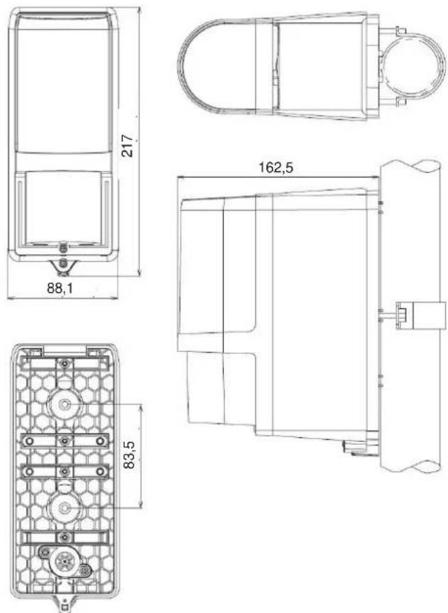
Fig. 10 Unit dimensions
JABLOTRON
JABLOTRON ALARMS a.s.
Pod Skalkou 4567/33
lonec nad Nisou Czech Republic
Tel: +420 483 559 911
Fax: +420 483 559 993
Internet: www.jablotron.cz