3579-GML - Kontor Bretford - Tasuta kasutusjuhend
Leidke seadme juhend tasuta 3579-GML Bretford PDF-formaadis.

Kasutajate küsimused teemal 3579-GML Bretford
0 küsimus selle seadme kohta. Vastake nendele, mida teate, või esitage oma.
Esita uus küsimus selle seadme kohta
Laadige alla juhend oma Kontor PDF-formaadis tasuta! Leidke oma juhend 3579-GML - Bretford ja võtke oma elektrooniline seade uuesti kätte. Sellel lehel on avaldatud kõik teie seadme kasutamiseks vajalikud dokumendid. 3579-GML kaubamärgi Bretford.
KASUTUSJUHEND 3579-GML Bretford

BRETFORD
3579 3589
INSTRUCTION CENTER WITH SHELF
Assembly Instructions
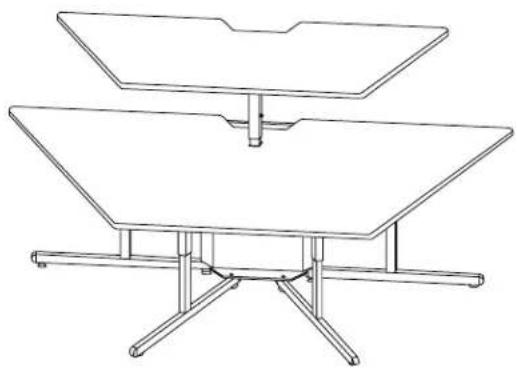
natural_image
Line drawing of a two-tiered table with legs and supports (no text or symbols)PARTS LIST HARDWARE LIST
Qty Part# Description
4 022-1904 Lower Legs (3579)
022-1902 Lower Legs (3589)
4 022-1903 Upper Legs
1 022-1905 Lower Shelf Support
1 022-1906 Upper Shelf Support
1 010-3156 Upper Bin Cover
1 010-3157 Upper Bin
1 010-3158 Lower BinCover
1 010-3159 Lower Bin
1 010-3155 Crosstie, Extension Mount
1 SA2161 3579 Table Top
SA2163 3589 Table Top
1 SA2160 3579 Shelf Surface
SA2162 3589 Shelf Surface
Ref Qty Part# Description
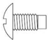
AA 48 030-0304 1/4-20 x 5/8" Combo Screw
BB 12 030-0396 3/8-16 x 1/2" Set Screw
CC 8 015-0084 3/8-16" Glides
DD 12 030-0325 1/4-20 x 1/2" Combo Truss Screw
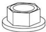
EE 2 030-0256 1/4-20 Flange Hex Nut
1 030-0397 Allen Wrench
TOOLS REQUIRED
Phillips Screwdriver
Allen Wrench (provided)
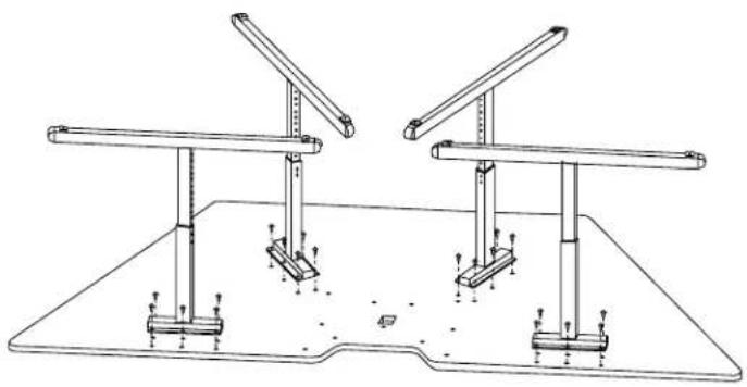
natural_image
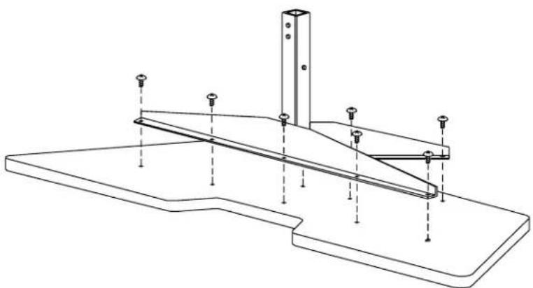
Technical line drawing of two identical support structures mounted on a base plate, with no text or symbols present.STEP 1
Lay table top down with mounting holes facing up. Attach legs to table top with 1/4-20 x 5/8" combo screws (AA) as shown.
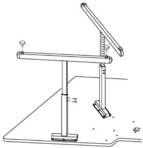
natural_image
Technical line drawing of a mechanical support structure with no visible text or symbolsSTEP 2
Set desired height on legs and insert screws (BB) and tighten with Allen wrench to lock legs in place. Also screw glides into all legs as shown.
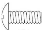
AA
BB
natural_image
Technical line drawing of a mechanical assembly with brackets and mounting feet (no text or symbols)STEP 3
Set table on its front edge and attach lower shelf support stem through the cutout and secure with 1/4-20 x 5/8" combo screws (AA) as shown.
natural_image
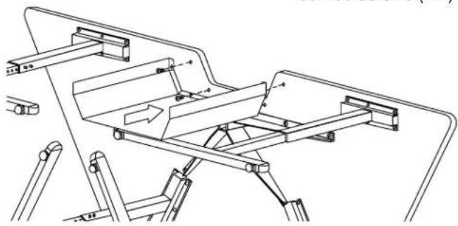
Technical line drawing of a mechanical assembly with no visible text or symbolsSTEP 4
Install Upper Bin with 1/4-20 x 5/8" combo screws (AA) as shown.
natural_image
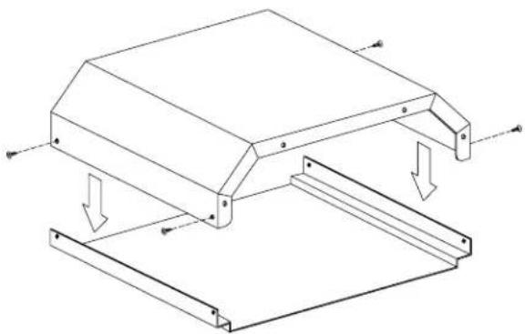
Technical line drawing of a mechanical frame assembly with downward force arrows indicating load or compression (no text or symbols)STEP 6
Assemble Lower Bin and Upper Bin with 1/4-20 x 1/2" combo screws (DD) as shown.
DD
EE
natural_image
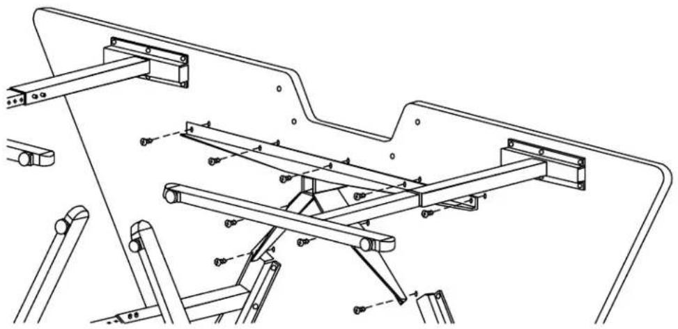
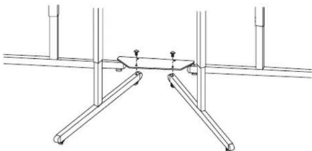
Technical line drawing of a structural support frame with vertical and horizontal beams (no text or symbols)STEP 5
Stand the table upright and attach Crosstie, Extension Mount with 1/4-20 x 1/2" combo screws (DD) as shown.
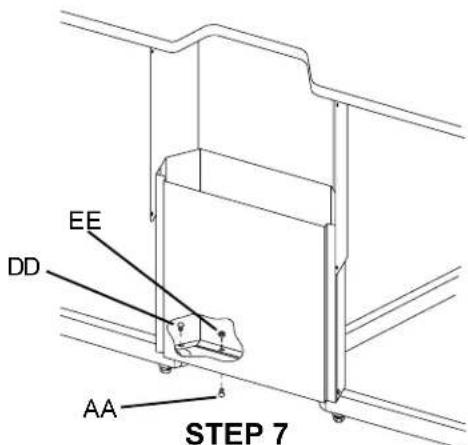
Install Lower Bin assembly with 1/4-20 x 5/8" combo screws (AA), 1/4-20 x 1/2" combo truss screw (DD) and 1/4-20 nut (EE) as shown.
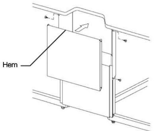
STEP 8
Install Upper Bin Cover (hem at top) with 1/4-20 x 1/2" combo screws (DD) as shown.
natural_image
Technical line drawing of a structural support frame with mounting holes and vertical supports (no text or symbols)STEP 9
Lay shelf down with mounting holes facing up. Attach upper shelf support to shelf with 1/4-20 x 5/8" combo screws (AA) as shown.
natural_image
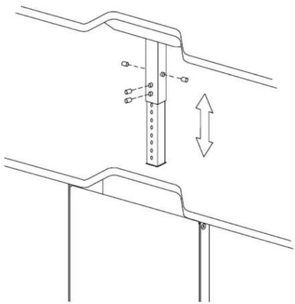
Technical line drawing of a structural support frame with mounting holes and a vertical beam, showing dimension arrows (no text or symbols)STEP 10
Slide upper shelf support onto lower shelf support. Align the holes for the desired height, insert screws (BB) and tighten with Allen wrench to lock in place.
Bretford Bretford Ltd.
11000 Seymour Avenue Technology House
Franklin Park, IL 60131 7 Lake End Court, Taplow
TEL: 847.678.2545 Bucks SL6 0JQ England
800.521.9614 TEL: 01628 603558
FAX: 847.678.0852 FAX: 01628 604923
800.343.1779
www.bretford.com
Part #031-3180
Rev. 01.15.99 BW