NXF-MINI - Controller AMX - Free user manual and instructions
Find the device manual for free NXF-MINI AMX in PDF.


| Product Type | Control System/Controller |
| Brand | AMX |
| Model | NXF-MINI |
| Dimensions (approx) | 4.5 x 2.5 x 1 in (114 x 64 x 25 mm) |
| Weight (approx) | 0.5 lb (227 g) |
| Power Supply | 5V DC via USB or AC adapter (not included) |
| Power Consumption | < 5W |
| Main Functions | Control AV devices, automation, system integration, custom programming |
| Connectivity | Ethernet, RS-232, IR, relay, I/O ports |
| Operating Temperature | 32°F to 104°F (0°C to 40°C) |
| Storage Temperature | -4°F to 140°F (-20°C to 60°C) |
| Humidity Range | 10% to 90% non-condensing |
| Mounting | Desktop or rack-mount kit (optional) |
| Maintenance | Keep dry; clean with soft, dry cloth; avoid liquids |
| Safety | Indoor use only; low voltage; no user-serviceable parts |
| Spare Parts & Repairability | No user-replaceable parts; contact AMX support for service |
| General Information | Designed for commercial and residential AV control |
Frequently Asked Questions - NXF-MINI AMX
User questions about NXF-MINI AMX
0 question about this device. Answer the ones you know or ask your own.
Ask a new question about this device
Download the instructions for your Controller in PDF format for free! Find your manual NXF-MINI - AMX and take your electronic device back in hand. On this page are published all the documents necessary for the use of your device. NXF-MINI by AMX.
USER MANUAL NXF-MINI AMX
The NXF-MINI NetLinx Mini CardFrame (FG2104) provides up to 4 expansion card slots that accept any combination of compatible NetLinx Control Cards (see Specifications table below).
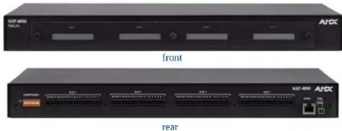
FIG. 1 NXF-MINI NetLinx Mini CardFrame
The NXF-MINI is compatible with any NetLinx Controller or Master. The unit is one rack unit high and connects via ICSNet communications to the controller system.
This unit is ideal for expansion or distributed systems needing additional IR, Relay, and Volume Control capabilities. Current features include:
• Flexibility and custom control options.
• Supports for up to four NetLinx Control Cards.
- Front access to all four card slots.
- Ease of use and installation.
Multiple MINIs can be connected using ICSNet Hubs.
Specifications
| NXF-MINI Specifications | |
| Dimensions (HWD): • 1.75" x 17.00" x 9.56" (4.45 cm x 43.18 cm x 24.28 cm)• 1 R U | |
| Power: • 25 mA @ 12 VDC | |
| Weight: • 6.20 lbs (2.81 kg) | |
| Enclosure: • Metal with black matte finish | |
| Front Panel: • NetLinx Control Card Slots 1- 4: Accept up to 4 compatibleNetLinx Cards: such as the NXC-COM2, NXC-I/O10, etc.• Rack-mount brackets: Provides an installation option for the NXF-MINI to be mounted into an equipment rack. | |
| Rear Panel: • CardFrame Number DIP Switch: Sets the starting address for the Control Cards in the CardFrame. The 8-position DIP switch address range is 1-3064. (Factory default CardFrame DIP switch value = 0). The Control Card address range is 1-3064.• NetLinx Control Card Connectors (1-4): Four 20-pin (male) connectors that bridge the gap between the Control Cards in the CardFrame and external equipment.• ICSNet Connector: Single RJ-45 connector for ICSNet interface.• Power Port: 2-pin 3.5 mm mini-Phoenix (male) connector. | |
| Included Accessories: | • Removable rack ear set (62-2104-03). Allows for tabletop, under-counter, and front/rear rack mounting• Quick Start Guide (93-2104)• Three faceplate screws (80-0181)• One 2-pin mini-Phoenix PWR connector (41-5025)• Installation Kit (KA2104):- 4 screws (#10-32 x 0.625)- 4 washers (#10 Black Nylon) |
| Optional Accessories: | • PSN6.5 power supply (FG423-41)• Accepts up to 4 compatible NetLinx Control Cards:NXC-COM2 Dual COM Port Control Card (FG2022)NXC-I/O10 Input/Output Control Card (FG2021)NXC-IRS4 4-Port IR/S Control Card (FG2023)NXC-REL10 Relay Control Card (FG2020)NXC-VAI4 Analog Voltage Control Card (FG2025)NXC-VOL4 Volume Control Card (FG2024) |
Note: The NXF-MINI requires a local 12 VDC Power Supply.
Connections and Wiring
FIG. 2 shows the layout of the connectors and components on the rear of the NXF-MINI.
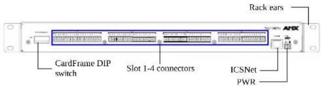
FIG. 2 Rear NXF-MINI connectors and components
Inserting NetLinx Cards into the NetLinx Control Card Slots
The optional NetLinx Cards can be installed horizontally into the NXF-MINI through the card slot openings on the front of the enclosure.
To install a NetLinx Card:
-
Discharge the static electricity from your body by touching a grounded metal object and unplug all the connectors from the unit.
-
Remove the three (3) screws by turning them in a counter-clockwise direction and remove the front faceplate.
-
Align the edges of the card with the internal guide slots and gently slide the card all the way in until you feel the rear edge of the card lightly snap into place.
-
Re-secure the faceplate by inserting the three (3) screws by turning them in a clockwise direction and securing the front faceplate to the NXF-MINI.
-
Re-apply power and other connections as necessary.
Setting the MINI's Control Card starting Card Address
The 8-position CardFrame Number DIP switch, located on the lower-left rear of the CardFrame, sets the starting address (the device number in the D:P:S specification) for the Control Cards installed in the unit.
The Control Card address range is 1-3064. The factory default CardFrame DIP switch value = 0 (All CardFrame DIP switches in the OFF position).
The formula for setting the starting address is:
(DIP switch value) + Card slot Number (1-4) = Card Address
For example:
For DIP switch setting, 00010101:
(0 + 0 + 0 + 96 + 0 + 384 + 1536) + SLOT #(ex:1) = 2017.
A card in slot number 1 = device address 2018.
Set the CardFrame Number DIP switch based on the table below.
| Position 1 | 2 | 3 | 4 | 5 | 6 | 7 | 8 | |
| Value | 12 | 24 | 48 | 96 | 192 | 384 | 768 | 1536 |
Cycle power to the unit for approximately 5 seconds. This allows the unit to read the new device number settings.
Using the PSN NetLinx connector for power
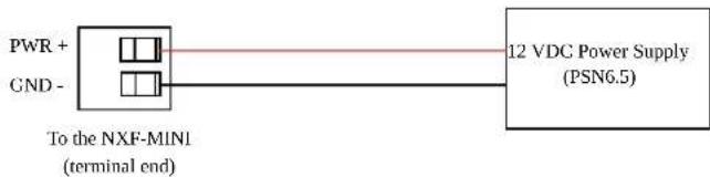
To supply power from the local power supply to the rear 2-pin mini-Phoenix power jack; the incoming PWR and GND cables from the power supply must be connected to the corresponding location on the NXF-MINI 2-pin 3.5 mm mini-Phoenix connector (FIG. 3).
flowchart
graph LR
    A["PWR + GND"] --> B["To the NXF-MINI (terminal end)"]
    B --> C["12 VDC Power Supply (PSN6.5)"]
FIG. 3 NetLinx power connector wiring diagram
- Insert the PWR and GND wires into the terminal end of the PSN 2-pin 3.5 mm mini-Phoenix cable.
- Tighten the clamp to secure the two wires.
- Verify the connection of the other end to the mini-Phoenix connector on the power supply.
ICSNet Connections/Wiring
This connector uses a standard CAT5 Ethernet cable to provide communication between the CardFrame and the NetLinx control system processor. The following table shows the signal and pinout information associated with the ICSNet connections.
ICSNet Signals and Pinouts
| Pin Signal-Master Signal-Device | |||||||
| 1 | T | X | + | R | X | + | |
| 2 | T | X | - | R | X | - | |
| 3 | N | / | A | N | / | A | |
| 4 | G | N | D | G | N | D | |
| 5 | N | / | A | N | / | A | |
| 6 | N | / | A | N | / | A | |
| 7 RX + | TX + | ||||||
| 8 RX - | TX - | ||||||
Note: ICSHub cable information is used when connecting an NXF-MINI (from the rear ICSNet connector) to an external Hub (ex: ICSHub connector port on an NXC-NH).
ICSHub Connections/Wiring
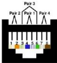
The following table shows the ICSHub pinout wiring, coloring, and functionality.
ICSHub Pinout Information (EIA/TIA 568 B)
| Pin Wire Color Polarity | Function | ||
| 1 Orange/White + | Transmit | ||
| 2 Orange - | Transmit | ||
| 3 Green/White - | - | ||
| 4 | Blue | - | - |
| 5 | White/Blue | + | - |
| 6 | Green | + | - |
| 7 White/Brown + | Receive | ||
| 8 Brown - | Receive | ||
flowchart
graph TD
    A["Pair 3"] --> B["Pair 2"]
    A --> C["Pair 1"]
    A --> D["Pair 4"]
    E["1"] --> F["2"]
    G["2"] --> H["3"]
    I["3"] --> J["4"]
    K["5"] --> L["6"]
    M["6"] --> N["7"]
    O["7"] --> P["8"]
TIA 568B
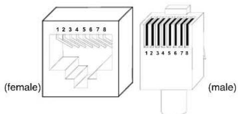
RJ-45 connector - pin configurations
Brand : AMX
Model : NXF-MINI
Category : Controller