
Axess Elite SX-AX20E - Energy Management System SurgeX - Free user manual and instructions
Find the device manual for free Axess Elite SX-AX20E SurgeX in PDF.


| Product Type | Energy Management System / Web-Enabled Power Conditioner |
| Brand | SurgeX |
| Model | Axess Elite SX-AX20E |
| Load Rating | 20 Amps at 120 Volts |
| Power Consumption (No Load) | 5 Watts |
| Number of AC Outlets | 8 (NEMA 5-15R) |
| Auxiliary Relay Outputs | 2 (Form C, NO/NC/COM) |
| Surge Protection | Advanced Series Mode® surge elimination, 0V let-through (6000V surge) |
| EMI/RFI Filtering | Impedance Tolerant®; up to 50 dB attenuation (normal mode) |
| Inrush Current Elimination (ICE) | On outlets 1 and 2 |
| Network Interface | 10/100 Ethernet (RJ-45), auto-negotiating |
| Serial Interface | RS-232 (DB9 female, DCE), 9600 baud default |
| Remote Control Protocols | Web (HTTP/HTTPS), Telnet, CLI, SNMP v2c, SDxP API |
| Sensor Inputs | Temperature sensor (2-pin screw terminal), Contact closure input (2-pin screw terminal) |
| Metering Accuracy | Voltage ±1%, Current ±1%, Power ±5% (resistive) |
| Dimensions (W x D x H) | 19 x 12.25 x 1.75 inches (1U rack mount) |
| Weight | 13 lb (5.9 kg) |
| Operating Temperature Range | 5°C to 35°C (41°F to 95°F) |
| Safety Certifications | ETL listed to UL 1449 (3rd Ed.), UL 1283 (5th Ed.), CSA 22.2 No. 8-M1986 |
| Maintenance | No user-serviceable parts; firmware upgrade via utility |
Frequently Asked Questions - Axess Elite SX-AX20E SurgeX
User questions about Axess Elite SX-AX20E SurgeX
0 question about this device. Answer the ones you know or ask your own.
Ask a new question about this device
Download the instructions for your Energy Management System in PDF format for free! Find your manual Axess Elite SX-AX20E - SurgeX and take your electronic device back in hand. On this page are published all the documents necessary for the use of your device. Axess Elite SX-AX20E by SurgeX.
USER MANUAL Axess Elite SX-AX20E SurgeX
Web-Enabled Power Conditioning and Energy Management System
User Manual
This product may be covered by one or more claims of the following patents or published patent application:
U.S. Patent Nos.: RE39,466; 2,461,332; 4,870,528; 4,870,534; 5,136,455; 6,040,969; 6,728,089; 6,744,613; 6,947,266;
7,068,487; 7,184,252; 7,511,934; 7,541,696; and 7,551,412; 8,482,885; 8,520,349; 8,547,672; 8,614,866; 9,166,396;
9,225,534; 9,310,870; 10,014,680; 10,090,622; 10,114,395
U.S. Patent Application Publication Nos.: 2012/0221161; 2013/0073232
Canadian Patent Nos.: 1,332,439; 1,333,191; 2,461,332 and 2,511,695
Table of Contents
- Introduction 5
- Initial Set Up 6
- Installation 7
3.1 120 Volt Connections 7
3.2 Ethernet Connections 7
3.3 RS232 (Serial) Port Connection 7
3.4 Temperature Sensor 8
3.5 Contact Closure Input 8
3.6 Auxiliary Relay Outputs 8
-
LED Indicators 8
-
Web Server 9
5.1 Login 9
5.2 Administration 9
5.2.1 Reset Factory Defaults 9
5.2.2 Backup/Restore 9
5.2.3 System Info 9
5.3 Device View 10
5.4 Global View 11
5.5 Setup 11
5.5.1 Device Setup 12
5.5.2 Network Setup 13
5.5.3 Network Reporting Setup 15
5.5.4 Users Setup 16
5.5.5 Triggers Setup 17
5.5.6 User Defined Triggers 18
5.5.7 Sequences Setup 19
5.5.8 Links Setup 20
- Command Line Interface (CLI) Protocol 21
6.1 Prompts 21
6.2 Syntax 21
6.3 Responses 21
6.4 CLI Documentation Notation 21
6.5 Device Commands 22
6.6 Network Commands 23
6.7 Calibration Commands 23
- Email Notification 24
8 SNMP 24 - SDxP Protocol 25
9.1 Overview 25
9.2 Hello Handshake 25
9.3 SDxP Packet 26
9.4 Types 27
9.5 Descriptors 27
9.6 Payloads 30
- Device Management Utility 32
- Syslog 33
- Rear Panel Reset Button 33
13 Firmware Upgrade 33 - Specifications 34
1. Introduction
The SurgeX® Axess Elite is a single rack-space, 120V, 15 (20) amp, AC power conditioner that can be controlled over a network or the internet, through a direct serial connection, or through a contact closure input. The simple web server structure allows basic control of the outlets and viewing of status information all from the home page. The extensive programming and setup capabilities are accessed in seven other pages or through a Command Line Interface (CLI).
The Axess Elite incorporates SurgeX Advanced Series Mode® power conditioning and surge elimination, SurgeX Impedance Tolerant® EMI/RFI filtering, and SurgeX ICE® Inrush Current Elimination circuitry (on receptacles 1 and 2). SurgeX ICE eliminates problems associated with inrush currents from large loads such as amplifiers. With SurgeX ICE, it is not necessary to take inrush currents into account when designing the AC power for a system. Special time-delay circuit breakers are not required – it is necessary only to ensure that the average currents of all products plugged into the Axess Elite are within the 15 (20) Amp product rating.
Telnet and serial access use the same Command Line Interface (CLI) structure and syntax to configure, monitor, and control the Axess Elite. The Axess Elite may also be monitored and controlled via SNMP and/or the SDxP API, and may be configured to report to a Syslog server. The internal web server may be secured with Secure Sockets Layer (SSL) encryption.
Two Auxiliary Relay outputs are provided for simple control of other equipment. Connection terminals are provided for each relay's Common, Normally Open, and Normally Closed connections.
Up to 16 Axess Elites can be linked together and controlled from a single web interface. One master Axess Elite provides the communication to the users and receives status information from the rest of the Axess Elites in the cluster. Up to 128 outlets can be controlled in this manner from one IP address.
Up to 16 users can be assigned administrator or user only rights, plus access to specific outlets.
The extensive programming capabilities of the Axess Elite allow sequencing and scheduling to be set up. User Triggers can be programmed to activate on an "if X then do Y then do Z when no longer X" basis. Triggers include: AC line voltage, total unit current draw, individual receptacle current draw, temperature, Net Test, and Contact Closure Input. Actions include: turning receptacles on and off, cycling a receptacle, executing previously-defined sequences, and sending emails. For example, an action can be created to send an email if the rack temperature exceeds 95oF.
The eight rear-mounted receptacles can each be individually controlled, and the current, power, and energy consumption of each receptacle can be obtained through the web page interface and CLI. The metering includes the AC line voltage and current draw, and all measurements (voltage, current and power) are true RMS readings. Thus, the current draw and energy consumption of non-linear electronic loads which have a power factor of less than unity will be correctly reported.
Located on the rear panel are the input power cord, circuit breaker (15A or 20A), 8 NEMA 5-15 AC outlets, Serial connection (DCE, 9 pin D-subminiature), Network connection (RJ-45), Temperature Sensor input, Contact Closure input, Auxiliary Relay A/B output connections, and recessed Reset button.
| Temperature Sensor | Contact Closure | Auxiliary Relay A | Auxiliary Relay B | ||||||
| Red | Black | CC1 | CC2 | NO | COM | NC | NO | COM | NC |
The thirteen front panel LEDs provide indications for eight AC outlet On/Off status (green), two Auxiliary Relay Latched/Unlatched status (green), surge protection status (green), Shutdown status (amber), and AC mains power (red).
| 1 | 2 | 3 | 4 | 5 | 6 | 7 | 8 | A | B | Self-Test | Shutdown | Mains | ||||
2. Initial Set Up
*Default user name and password: admin / admin
DHCP
*Beginning with firmware version 2.04.281, the factory default IP Mode will be DHCP (previously Static).
A DHCP Server will automatically assign an IP address (dynamic address) as well as Subnet Mask and Gateway to the Axess Elite.
To find the IP address of the Axess Elite, you will need to use the Discover function of the DMU, query your DHCP server and locate the MAC address of the Axess Elite in the DHCP server's IP/MAC table, or access the CLI via serial and use the get network command.
Command Line Interface (CLI)
Many configuration parameters may be set using the Command Line Interface (CLI). The CLI is accessed through the network using a telnet client, or through the serial port.
Open a telnet client and point it to the current IP Address of the Axess Elite. The factory default telnet port is 23.
Connect to the serial port. The factory default settings are 9600, 8, n, 1.
Upon connection, press Enter and then enter the user name and password when prompted. The factory default user name and password are admin / admin.
These are the basic commands to set the network parameters via CLI. After setting these parameters, the Axess Elite will need to be rebooted for the settings to take effect. Any command that requires rebooting of the Axess Elite will provide a prompt to do so. All commands may be entered as required before rebooting.
Example: Telnet to DHCP-Assigned IP Address 192.168.1.199 on Port 23 and change to Static IP Address 192.168.1.3.
Axess ELITE
Connected to Telnet Session 1

User> admin
Password> ****

Axess ELITE> set ipmode static

OK
Axess ELITE Reboot Required > set ipaddress 192.168.1.3

OK
Axess ELITE Reboot Required> set subnet 255.255.255.0

OK
Axess ELITE Reboot Required> set gateway 192.168.1.7

OK
Axess ELITE Reboot Required> reboot
3. Installation
The SurgeX Axess Elite is designed to be installed in a 19 inch equipment rack and requires one unit (1-U) of rack space. Use the four screws provided with the product to secure the rack ears to the rack rails. These screws can be tightened by hand and do not require tools. Connect power to the unit by plugging the cord into a 120V AC, 15 (20) amp wall or floor receptacle. Do not plug the unit into a relocatable power tap.
3.1 120 Volt Connections
The Axess Elite has a total of 8 receptacles. Each receptacle is rated for a maximum load of 15 amps, but the total load of the Axess Elite must not exceed 15 (20) amps. Plug the equipment cords into the receptacles as needed. The receptacles are numbered 1 through 8. This same numbering is used in the control interface.
3.2 Ethernet Connection
The RJ45 connector for Ethernet is situated on the rear panel beside the Serial connector. The default IP Address is DHCP assigned.
3.3 RS232 (Serial) Port Connection
The Axess Elite has a 9 pin D subminiature connector for RS-232 serial control. The connector is configured as DCE for direct connection to a laptop or other terminal device. Default serial parameters are 9600 bps, 8 data, no parity, 1 stop bit (9600,8,n,1).
3.4 Temperature Sensor
In order to obtain a temperature reading, the external temperature sensor must be connected to the first (far left) terminal block. The sensor has two wires: red and black. Connect the red wire to pin 1 and the black wire to pin 2. The sensor can be positioned to read air temperature at any location in the rack, although the top of the rack would be optimal since heat rises; it can also be placed in contact with the chassis of a particular piece of equipment that you want to monitor.
| Temperature | Contact Closure | Auxiliary Relay A | Auxiliary Relay B | ||||||
| Red | Black | CC1 | CC2 | NO | COM | NC | NO | COM | NC |
3.5 Contact Closure Input
Connect a contact closure control input (if any) to the 2 pins of the second terminal block. Relays, switches, and push buttons are all suitable input types. The actions to be executed upon closing or opening of the contact closure input may be defined as various User Triggers on the Triggers Setup web page.
3.6 Auxiliary Relay Outputs
Two auxiliary relay outputs are provided at the third (Aux Relay A) and fourth (Aux Relay B) terminal blocks. Access to the Common, Normally Open, and Normally Closed positions is provided for each relay. The auxiliary relays are controlled in the same manner as the AC outlets, and may be controlled by Sequences, Schedules, and User Triggers.
4. LED Indicators
There are thirteen LED indicators located on the front panel. Their function is as follows:
| 1 | 2 | 3 | 4 | 5 | 6 | 7 | 8 | A | B | Self-Test | Shutdown | Mains | ||||
| LED Indicators | ||
| Indicator | Color | Description |
| Outlets | Green | When illuminated, the corresponding AC outlet is on. |
| Aux Relays | Green | When illuminated, the corresponding auxiliary relay is latched. |
| Self-Test | Green | When illuminated, the surge suppression circuitry is functioning correctly. |
| Shutdown | Amber | When illuminated, the Axess Elite is in shutdown mode due to out of range line voltage, current, or temperature. |
| Mains | Red | When illuminated, the Axess Elite is connected to a live wall or floor outlet. |
5. Web Server
The web server is built around 4 pages: Login, Device View, Global View, and Setup. Each page is discussed in detail below.
5.1 Login
The Login page is the first page displayed when a web browser makes a connection to the Axess Elite. Enter a valid user name and password in the "User Name" and "Password" fields, and press "Login" to log in to the Axess Elite.
A mobile login page is available at IPAddress/mobile_login.html

5.2 Administration
5.2.1 Reset Factory Defaults
- Allows resetting of factory defaults from the web interface.
- Options to keep or reset network IP settings.
- Options to keep or reset calibration data.

- Provides Configuration Management via *.conf files.
- Backup current configuration to file.
- Restore configuration from previously saved file.
- Option to keep current network IP settings or use those in configuration file.
- Option to keep current calibration data or use calibration values in configuration file.
- If restoring the calibration values stored in a configuration file, there is an option to only restore the values if the MAC address of the unit and the MAC address in the configuration file match.

5.2.3 System Info
- Displays number of logged in web users, time each user has been logged in, and System uptime. Also provides a Reboot button

5.3 Device View
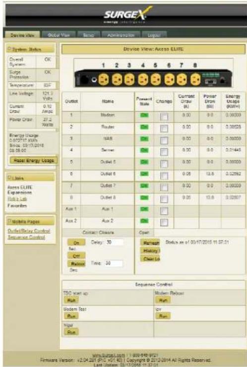
The Device View page provides information and status for the whole unit and individual outlets, as well as basic control of outlets. The top left section of the page provides system status. To refresh the status information, click the "Refresh" button.
For each outlet the Outlet Name, Present State, Current Draw, Power Draw, and Energy Usage are displayed.
Mobile Page links are at the bottom left below the Links section.
Contact Closure input status is displayed.
| Device View | |
| Item | Description |
| Overall System | Indicates that the surge protection, rack temperature, line voltage, and current draw are at acceptable levels. |
| Surge Protection | Indicates that the surge protection is fully functional. |
| Rack Temperature | Displays the temperature of the sensor that is connected to the rear terminal block. If the temperature sensor is not connected, the display will read “NC” |
| Line Voltage | Displays the true-RMS AC voltage. |
| Current Draw | Displays the total current draw of all 8 receptacles in true-RMS Amps. |
| Power Draw | Displays the total power draw of all 8 receptacles in Watts. |
| Energy Used | Displays the total energy consumption of the equipment plugged into the unit in KW- Hours since the last counter reset. Pressing “Reset Energy Usage” will reset the KW- Hours count. |
| On | Turns the selected outlets on, staggered by the Delay time. |
| Off | Turns the selected outlets off. |
| Reboot | Turns the selected outlets off for the length of the Reboot Time, and then back on. |
| History Log | Displays the internal history log (if enabled). |
5.4 Global View
The Global View page displays the current outlet states and system status for the Axess Elite and expansion units. Up to 15 expansion units may be set up on the Links Setup page.
Outlets and Aux Relays may be commanded to turn On, Off, or Reboot for up to 16 Axess Elite units (1 master and 15 expansions).

In order to have rights to control expansion unit outlets, the user's identical user name and password must be programmed into each expansion Axess Elite to be managed.
5.5 Setup
Complete setup and configuration of the Axess Elite is provided via 7 Setup web pages. Each setup page is described in the following sections.
| Setup | |
| Setup Page | Description |
| Device | Configure basic device parameters |
| Network | Configure network settings, including the network adapter, email, and time keeping |
| Network Reporting | Configure SNMP, SDxP, and Syslog reporting |
| Users | Configure user accounts |
| Triggers | Configure System TriggersCreate and modify User Triggers |
| Sequences | Create and modify custom Sequences |
| Links | Create and modify Expansion units and Favorite links |
5.5.1 Device Setup
The Device Setup page allows for the specification of basic device parameters.
Saving any change which requires a reboot to take effect will result in the addition of a "Reboot Required" button at the bottom of the page.

| Device Setup | |
| Item | Description |
| On Power Up | Specify whether to set outlets to Initial States or run a predefined Sequence when the Axess Elite powers up, or the Reset button is pushed, or a soft reboot is commanded. |
| Device Name / Hostname | Specifies the name label to be associated with the Axess Elite. This name also serves as the Hostname. |
| Power Up Delay Time | Specifies the amount of time in seconds by which to stagger the manual turning on of multiple outlets. |
| Reboot Time | Specifies the amount of time an outlet is to remain off during a Reboot operation. |
| Temperature Display | Specifies whether to display temperature in degrees Fahrenheit or Celsius. |
| User Accounts May Clear Shutdown | Specifies whether or not a non-administrative user account is allowed to manually clear a persistent shutdown state. |
| Serial Baud Rate | Specifies the baud rate to be used with the serial interface. |
| Serial Port Requires Login | Specifies whether or not a serial CLI session requires login. |
| Auto Logout | Specifies the web and telnet security timeout in minutes. |
| Use History Logging | Specifies whether or not to keep an internal log file. |
| Allow Firmware Upgrade | Specifies whether or not the Axess Elite is in an upgradeable state. |
| Outlet Name | Allows for the specification of name labels for each outlet. |
| Initial State | Specifies the state the outlet will take following a loss of power or the clearing of a shutdown event. |
| ICE | Specifies whether or not to activate Inrush Current Elimination for outlets 1 and 2. |
| On Shutdown Clear | Specify whether to set outlets to Initial States or run a predefined Sequence when a Shutdown State clears. |
| Aux 1 Confirmation | Enables/disables "Confirmation Mode" for Aux Relay 1, wherein Aux 1 will be latched only when all AC outlets are On. |
5.5.2 Network Setup
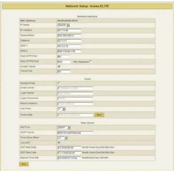
The Network Setup page allows for the specification of network settings, including the network adapter, email, and time keeping.
Saving any change which requires a reboot to take effect will result in the addition of a "Reboot Required" button at the bottom of the page.
| Network Setup | |
| Item | Description |
| IP Setup | Specifies whether to use Static or DHCP mode. |
| IP Address | Specifies the address to be used when in Static mode, and displays the assigned address when in DHCP mode. |
| Subnet Mask | Specifies the subnet mask to be used when in Static mode, and displays the assigned mask when in DHCP mode. |
| Gateway | Specifies the gateway address to be used when in Static mode, and displays the assigned gateway address when in DHCP mode. |
| DNS1 | Specifies the first DNS server address to be used when in Static mode, and displays the acquired address when in DHCP mode. |
| DNS2 | Specifies the second DNS server address to be used when in Static mode, and displays the acquired address when in DHCP mode. |
| Web HTTP Port | Specifies the port that the web server will communicate on. If the port number is changed from the default value of 80, the Axess Elite's web pages may be accessed by navigating to "http://IPADDRESS:PORTNUMBER"; for example, "http://192.168.1.199:72". |
| Web HTTPS Port | Specifies the port that the web server will communicate on when using secure SSL encryption. |
| SSL Required | Specifies whether or not the internal web server is to use secure SSL encryption. |
| Enable Telnet | Specifies whether or not to enable the internal telnet server. |
| Telnet Port | Specifies the port the internal telnet server will communicate on. |
| Enable Email | Specifies whether or not to enable the sending of email messages. |
| Email Server | Specifies the IP Address of the SMTP or ESMTP server to be used. |
| Login Name | Specifies the user name for the mail server. |
| Login Password | Specifies the password for the mail server. |
| Return Address | Specifies the return address of the internal email client. |
| Auto Retry | Specifies the number of retries for failed email reporting. |
| Test Email | Sends a test email message to the specified address. |
| Set Time | Specifies whether to use Manual or internet SNTP timekeeping. |
| SNTP Server | Specifies the address of the internet time server when using SNTP mode. |
| Time Zone Offset | Specifies the time zone the Axess Elite is in. |
| Use DST | Specifies whether or not to automatically adjust for Daylight Savings Time |
| DST Start Date | Specifies the Month, Week, Day, and Time that DST starts. |
| DST Stop Date | Specifies the Month, Week, Day, and Time that DST ends. |
| Manual Time Set | Specifies the starting date and time when using Manual mode. |
5.5.3 Network Reporting Setup
The Network Reporting Setup page allows for the configuration of SNMP, SDxP, and Syslog reporting.
Saving any change which requires a reboot to take effect will result in the addition of a "Reboot Required" button at the bottom of the page.

| Network Reporting Setup | |
| Item | Description |
| Enable SNMP | Specifies whether or not to enable the SNMP v2c agent. |
| Read Community | Specifies the read community string. |
| Write Community | Specifies the write community string. |
| SNMP Managers | Specifies IP addresses for up to 4 SNMP managers. |
| Traps Sent | Specifies which specific traps are to be sent. |
| SDxP Port | Specifies the port to be used with the SDxP exchange protocol.The SDxP protocol is the means of communication between master and expansion units (all of which must use the same SDxP port), and is also the API to be used with the Axess Elite. |
| SDxP Manager | Specifies the IP address of the SDxP manager. |
| SDxP Status Broadcast | Specifies whether or not to enable a status broadcast and the frequency of the broadcast messages in minutes. |
| SDxP Event Reporting | Specifies which items are accessible by the SDxP protocol. |
| SDxP Encryption | Specifies whether or not to use AES encryption with a shared passphrase. |
| Syslog Port | Specifies the port to be used with a Syslog server. |
| Syslog Server | Specifies the IP address of a Syslog server. |
5.5.4 Users Setup
The Users Setup page allows for the creation, deletion, and editing of up to 8 user accounts. Each user will have a unique user name, password, and email address, and may be assigned access to specific outlet(s).
User accounts may be of the Administrator or User type.
Administrators have access to all functions; Users do not have access to Setup functions.

User authentication is supported for Web, Serial, Telnet, and SDxP interfaces.
| Users Setup | |
| Item | Description |
| New User | Allows for the creation of a new user account. |
| Save | Saves the updated user information. |
| Close | Closes the edit dialogue without saving any changes. |
5.5.5 Triggers Setup
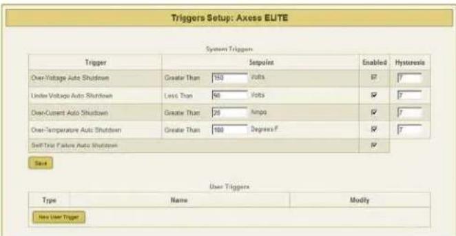
The Triggers Setup page allows for the modification of System Triggers and creation of User Triggers.
System Triggers define the protective shutdown points for the AC outlets, and take precedence over all other actions, including User Triggers.
| Triggers Setup | |
| Item | Description |
| Hysteresis | Specifies the amount by which the associated parameter must return closer to nominal following the activation of a System Trigger for the shutdown to be considered clear. For example using an over voltage shutdown point of 150V and a hysteresis of 7: The Axess Elite will enter a shutdown state when the line voltage exceeds 150V and will not leave the shutdown state until the line voltage drops below 150 - 7 = 143V. |
| Over-Voltage Auto Shutdown | Immediately shuts off all outlets if the AC line voltage rises above the set value. May not be disabled. |
| Under-Voltage Auto Shutdown | Shuts off all outlets if the AC line voltage falls below the set value. May be disabled. |
| Over-Current Auto Shutdown | Shuts off all outlets if the total current draw exceeds the set value. Once this has been triggered, the unit will stay in a persistent shutdown state until manually cleared by pressing “Clear Shutdown” on the Device View page or by issuing the CLI commandclear shutdown. The over-current shutdown point should not be set too close to the anticipated normal operating current draw, as this could cause an inadvertent shutdown. May be disabled. |
| Over-Temperature Auto Shutdown | Shuts off all outlets if the temperature sensed by the external temperature sensor exceeds the set value. Once this has been triggered, the unit will stay in a persistent shutdown state until manually cleared by pressing “Clear Shutdown” on the Device View page or by issuing the CLI commandclear shutdown. May be disabled. |
| Self-Test Failure Auto Shutdown | Shuts off all outlets in the unlikely event that the internal surge protection circuitry fails.Once this has been triggered, the unit will stay in a persistent shutdown state until manually cleared by pressing “Clear Shutdown” on the Device View page or by issuing the CLI commandclear shutdown. May be disabled. |
| Persistent Shutdown State: | The Axess Elite will enter a Persistent Shutdown State upon registering an Over- Current, Over-Temperature, or Self-Test Failure event. While in this state, all 8 receptacles will be turned Off, and the front panel amber LED labeled “Shutdown” will be illuminated. Outlet control will not be restored until the shutdown is manually cleared by pressing one of the “Clear Shutdown” buttons located on the Device View page or by issuing the CLI commandclear shutdown. Before clearing the shutdown state, it is advised to verify that the combined current requirement of all equipment powered by the Axess Elite is less than the value specified by the Over-Current System Trigger, and that the measured temperature is less than the value specified by the Over- Temperature System Trigger. Note that Over-Voltage and Under-Voltage shutdown events will clear automatically when the line voltage returns to an acceptable level. |
5.5.6 User Defined Triggers
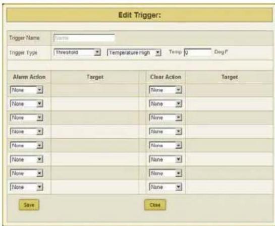
User defined triggers that have previously been created are displayed in a list. The name of the trigger is the name that was given to the trigger when it was created. Pressing "Test Alarm" will activate the trigger alarm action, and pressing "Test Clear" will activate the trigger clear action; use these test functions to verify that the trigger will operate as intended.
Pressing "Edit" will open the trigger for editing, and pressing "Delete" will delete the trigger. New triggers may be created by pressing the "New Trigger" button
| Type | Trigger Executes When: | Trigger Clears When: | |
| Threshold | Temperature High | Temperature > Set Point | Temp < Set - Hysteresis |
| Temperature Low | Temperature < Set Point | Temp > Set + Hysteresis | |
| Voltage High | Voltage > Set Point | Voltage < Set – Hysteresis | |
| Voltage Low | Voltage < Set Point | Voltage > Set + Hysteresis | |
| Line Current High | Total Current > Set Point | Current < Set – Hysteresis | |
| Line Current Low | Total Current < Set Point | Current > Set + Hysteresis | |
| Outlet Current High | Outlet X Current > Set Point | Current < Set – Hysteresis | |
| Outlet Current Low | Outlet X Current < Set Point | Current > Set + Hysteresis | |
| Net Test | IP Address Ping Fails | IP Address Ping Succeeds | |
| Schedule | Set Date and Time | NA | |
| Contact Closure | Contact Closure Input Closes | Contact Closure Input Opens | |
| Alarm/Clear Actions | Outlet On | Outlet Off | Outlet Reboot | Run Sequence | None |
5.5.7 Sequences Setup
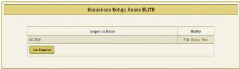
The Sequences Setup page allows for the creation and modification of sequences. A sequence is a list of outlets, including Auxiliary Relays, that will be turned On, Off, or Rebooted in a predetermined way with a specified delay time between each step. Using sequences avoids manually turning each outlet on or off individually.
A sequence, as defined for this product, is purely a one-way sequence. That is, you do not use the same sequence to turn outlets on as you use to turn the same outlets off in reverse order. One
sequence must be created for the turn-on function, and then a second sequence must be created for the turn-off function.
To create a new sequence, press the "New Sequence" button. The new sequence must be given a unique name. This name should clearly indicate what the sequence will do, such as "All On", "All Off" or "Stage Equipment On". There may be up to 16 steps in a single sequence. Select the time delay from
the "Pause" column. Select the outlet from the "Outlet" column. Select whether the outlet is to turn off, turn on, or reboot from the "Action" column. Press the "Save" button to save the sequence.
To run a sequence to test it, press "Run". To edit an existing sequence, press "Edit". To delete a sequence, press "Delete".
After a sequence has been saved, it will be available at the bottom of the Device View page, and when creating or editing a User Trigger when a sequence is selected as an action.

*Time delay is specified from the previous sequence item, not from the initial starting point. For example, creating a sequence with "Step 1, 1 second, Outlet 1, On" and "Step 2, 1 second, Outlet 2, On" will turn on Outlet 1 after 1 second, and Outlet 2 on 1 second after Outlet 1 has turned on. This sequence will not turn on both Outlets 1 and 2 at the same time.
5.5.8 Links Setup
The Links Setup page allows for the setup of Axess Elite Expansion units and Favorites.
Expansion units are other Axess Elite units which will be available for monitoring and control on the Global View page of the master unit. Up to 15 Expansion units may be defined.
Favorites may be any internet address. Use Favorites to set up shortcuts to earlier versions of the Axess Elite product, other equipment web servers, or Internet web pages.

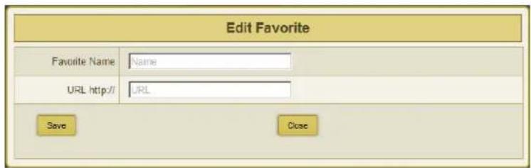
Addresses may be specified with a port number in this format: "http://IPADDRESS:PORTNUMBER"; for example, http://192.168.1.199:72.
Saved Expansions and Favorites are available in the Links subsection of the Device View page.
6. Command Line Interface (CLI) Protocol
The Command Line Interface provides complete setup of all functions of the Axess Elite. The CLI may be accessed either via the network interface using Telnet, or via the serial port using a terminal emulator program. Some commands of the CLI require administrative rights; these are indicated in the following tables.
6.1 Prompts
| Prompt | Description |
| User> | Prompt to enter a valid User Name. Not case sensitive. |
| Password> | Prompt to enter the Password associated with the User Name. Case sensitive. |
| Axess ELITE> | Standard prompt while logged in. |
| Axess ELITE Reboot Required> | Prompt after making a change which requires a reboot to take effect. |
6.2 Syntax
| Command | Description | Standard Syntax |
| Set | This command is used to change a parameter. | set |
| Get | This command is used to return the value of a parameter. | get |
| Add | This command adds an entry row to any array of variables. | add |
| Ren | This command renames an entry in an array. | ren |
| Del | This command deletes an entry from an array. | del |
6.3 Responses
| Response | Description |
| OK | The command was received and the syntax was validated. |
| Error | The syntax could not be validated. |
| Bad command or parameter | An incorrect command or parameter was received. |
| Invalid Command | An invalid command was received. |
6.4 CLI Documentation Notation
| Notation | Description |
| Text without brackets | Items you must type as shown |
| Placeholder for which you must supply a value | |
| Hyphen: - | Range of acceptable numeric values |
| Vertical Bar: | | Separator for mutually exclusive items; choose one |
6.5 Device Commands
| Command | Description | Admin | Fact Def |
| get allget outletsget status | Returns the status of all AC outlets and the following system level measurements:Device NameLine VoltageTotal Current DrawTotal Power DrawTotal Energy UsedReboot Time Currently in UseDelay Time Currently in UseTemperatureOn/Off Status of Each OutletCurrent Draw of Each OutletPower Draw of Each Outlet | No | |
| get outlet <1-10> | Returns the status of the specified outlet. AC outlets are numbers 1-8. Aux Relays A and B are numbers 9 and 10. | No | |
| set outlet <1-10><on/off/reboot> | Sets the selected outlet to the selected state. The user must have rights to the selected | No | |
| get devicename | Returns the device name. | No | Axess ELITE |
| set devicename | Sets the device name. | Yes | |
| get reboot | Returns the Reboot Time. | No | |
| set reboot <1-99> | Sets the Reboot Time in seconds. | No | 5 |
| get delay | Returns the Delay Time. | No | |
| set delay <0-99> | Sets the Delay Time in seconds. | No | 1 |
| get console | Returns the current console timeout and baud rate. | No | |
| set autologout <0-99> | Sets the automatic logout timeout of web and CLI in minutes. 0 = no timeout. | Yes | 2 |
| set baud < 2400 | 9600 | 57600 | 115200 > | Sets the serial port baud rate. | Yes | 9600 |
| clear shutdown | Clears a persistent shutdown state. | No | |
| set clear shutdown by user < yes | no > | Sets the ability of a user account to clear a persistent shutdown state. | Yes | Y |
| get upload enable | Returns the status of the ability to accept a firmware upload. | No | |
| set upload enable < yes | no > | Sets the ability to accept a firmware upload. | Yes | Y |
| clear log | Clears history text log file. | Yes | |
| set factory defaults | Resets all parameters, except Network Settings, to their factory default settings.Confirmation is required. Note: This command may take up to 30 seconds to execute. | Yes | |
| logout | Ends the session. | No | |
| reboot | Reboots the unit. Will not affect the status of the outlets. | No |
6.6 Network Commands
| Command | Description | Admin | Fact Def |
| get network | Returns the network settings. | Yes | |
| get mac | Returns the MAC address of the network adapter. | Yes | |
| set ipmode < static | dhcp > | Sets the IP Mode. | Yes | DHCP |
| set ipaddress < dotted decimal > | Sets the IP Address in dotted decimal. | Yes | DHCP Assigned |
| set subnet < dotted decimal > | Sets the subnet mask in dotted decimal. | Yes | 255.255.255.0 |
| set gateway < dotted decimal > | Sets the gateway in dotted decimal. | Yes | 0.0.0.0 |
| set dns1 < dotted decimal > | Sets the DNS server 1 address. | Yes | |
| set dns2 < dotted decimal > | Sets the DNS server 2 address. | Yes | |
| set web http port < 1 – 65535 > | Sets the web server port. | Yes | 80 |
| set web use ssl < yes | no > | Enable or Disable the web server's SSL capabilities. | Yes | No |
| set web https port < 1 – 65535 > | Sets the SSL web server port. | Yes | 443 |
| set telnet enable < yes | no > | Enable or disable the telnet server. | Yes | Yes |
| set telnet port < 1 – 65535 > | Sets the telnet port. | Yes | 23 |
6.7 Calibration Commands
IMPORTANT: Each Axess Elite is fully calibrated at the factory. Improper calibration may result in a Persistent Shutdown State!
| Command | Description | Admin | Standard Value |
| set voltage calibration < 105 – 130 > | Sets the voltage calibration. AC Volts. | Yes | 120 |
| set voltage offset < 0 – 130 > | Zeroes the voltage calibration. AC Volts. | Yes | 0 |
| set current < 1-8 | all > calibration < 1 – 20 > | Sets the individual outlet current calibration. AC Amps. | Yes | |
| set current < 1-8 | all > offset < -20 – 20 > | Zeroes the individual outlet current calibration. AC Amps. | Yes | 0 |
| set power < 1-8 | all > calibration < 1 – 2400 > | Sets the individual outlet power calibration. AC Watts. | Yes | |
| set power < 1-8 | all > offset < -20 – 20 > | Zeroes the individual outlet power calibration. AC Watts. | Yes | 0 |
| set temperature offset < -999 – 999 > | Sets the temperature calibration offset. Degrees F. | Yes | -460 |
7. Email Notification
Email can be automatically sent for System Triggers and User Triggers.
Emails generated by the Axess Elite will display the device name and information related to the System Trigger or User Trigger.
Examples:
Subject : Axess ELITE Cabinet_1
Date : Sat, 7 Jul 2012 09:41:00 - 0500
From : AxessElite@surgex.com To : networkadmin@yourco.com
Axess ELITE Cabinet_1 at 192.168.1.199
System Trigger Over Temperature at 115 degrees Alarm
Subject : Axess ELITE Cabinet_3
Date : Sat, 7 Jul 2012 09:46:00 - 0500
From : AxessElite@surgex.com
Axess ELITE Cabinet_3 at 192.168.1.199 schedule1 processed at 09:46 on 07/07/2012
8. SNMP
Axess Elite Setup and Control functions can be linked to any SNMP v2c manager. Up to four SNMP managers may be set. Each manager can perform all Setup and Control functions, and may receive Trap notifications for System Triggers, User Triggers, and Manual outlet control.
The Axess Elite MIB is available at surgex.com.
9. SDxP Protocol
9.1 Overview
The SDxP Protocol is a packet-based protocol designed to be extensible. This protocol is transmitted over TCP on a user-defined port. The factory default SDxP port is 9100.
The protocol uses a Hello handshake to establish unique sequence numbers to allow for advanced security when AES encryption is used. With AES enabled, all messages must be encrypted with the AES Passphrase set in the device.
After the Hello, a Command and Response sequence follows. Any number of Command → Response sequences are permitted after Hello.
9.2 Hello Handshake
The client sends a Hello message in the form of a text string "hello-000". The SDxP enabled Axess Elite will respond with a packet containing the unsigned 16 bit sequence number. This sequence number is incremented by the client and server with each correct packet sent.
Example:
| Client | Server |
| hello-000 → | |
| ← 1234 (seq 1234) | |
| Command → (seq 1235) | |
| ← Response | |
| Command → (seq 1237) | |
| ← Response |
9.3 SDxP Packet
The packet is broken up into 2 parts: the Header and the Payload
Header
The header is used to carry general information, such as is shown in the C programming structure below:
typedef struct { eType
    type; char[21]
    uName; char[21]
    password; uChar
    desc;
    uChar param;
    uint16 seq;
} THeader
| Variable | Description |
| type | Enumerated type that tells the SDxP server what type of packet is being sent. See the Types subsection for a full list of packet types. |
| uName | This variable MUST contain a valid user on the target Axess Elite. |
| password | This variable MUST contain the password for the specified user. |
| desc | This variable is the type descriptor that describes the type of data that is being sent. By extension, it lets the server know what the payload is. There is a different set of descriptors for each type class. See the Descriptors subsection for a full list of descriptors by type. |
| param | Reserved for future use. Optional parameter that may be passed to the server in addition to the descriptor. |
| seq | The packet's sequence number. Used as part of the security scheme. |
Payload
The payload is determined by a combination of the type class and the descriptor. The payloads are described by the descriptor; see the Descriptors subsection for details.
9.4 Types
There are currently 2 types. All classes are defined in the C programming enumerated type definition below:
typedef enum {
    eType_null,
    eType_inform,
    eType_commands
} eCmnd;
| Command | Description | |
| 0 | eType_null | This is a null command and should not be sent to the server. |
| 1 | eType_inform | Informs are similar to SNMP traps. They are sent from the managed device to the manager on a periodic basis. |
| 2 | eType_commands | Used to control and query the managed device. |
9.5 Descriptors
Descriptors are used to describe the individual commands within a command class and the payload that the packet contains. All of the descriptors and their payloads are outlined by command class below:
eType_Informs
    Informs are similar to SNMP traps. They are sent from the managed device to the manager on a periodic basis.

typedef enum { eInform_null,
    eInform_outletStatus,
    eInform_auxRelayStatus,
    eInform_lineVoltage,
    eInform_lineCurrent,
    eInform_linePower,
    eInform_ouletCurrent,
    eInform_outletPower,
    eInform_sysStatus,
    eInform_poll,
    eInform_overVoltager,
    eInform_underVoltage,
    eInform_overCurrent,
    eInform_overTemperature,
    eInform_selfTestFail,
    eInform_userTriggerClear,
    eInform_userTriggerFail,
    eInform_manualControl
    eInform_systemTriggerClear
}eInform;
Descriptors
| Inform | Description | Payload |
| eInform_outletStatus | This inform is used to tell the manager the status of all 8 outlets. It is also the response to the getOutletStatus and setOutletStatus commands. | tOutletStatus |
| eInform_auxRelayStatus | This inform is used to tell the manager the status of the 2 auxiliary relays. It is also the response to the getAuxRelayStatus and setAuxRelayStatus commands. | tAuxStatus |
| eInform_lineVoltage | This inform is used to tell the manager the line voltage. It is also the response to the getLineVoltage command. | tLineVoltage |
| eInform_lineCurrent | This inform is used to tell the manager the total line current. It is also the response to the getLineCurrent command. | tLineCurrent |
| eInform_linePower | This inform is used to tell the manager the total line power. It is also the response to the getLinePower command. | tLinePower |
| eInform_outletCurrent | This inform is used to tell the manager the current draw of each of the individual outlets. It is also the response to the getOutletCurrent command. | tOutletCurrent |
| eInform_outletPower | This inform is used to tell the manager the power draw of each of the individual outlets. It is also the response to the getOutletPower command. | tOutletPower |
| eInform_sysStatus | This inform is used to tell the manager the entire system status (all above metrics). It is sent every X minutes by the managed device to keep the manager in sync. It is also the response to the getSysStatus command. | tSysStatus |
| eInform_poll | This inform is used as the response to the Poll command. The Poll command is used by the Axess Elite to poll Expansion units. | tPoll |
| eInform_overVoltage | This inform is sent whenever a System Trigger: Over Voltage occurs. | tInformOverVoltage |
| eInform_underVoltage | This inform is sent whenever a System Trigger: Under Voltage occurs. | tInformUnderVoltage |
| eInform_overCurrent | This inform is sent whenever a System Trigger: Over Current occurs. | tInformOverCurrent |
| eInform_overTemperature | This inform is sent whenever a System Trigger: Over Temperature occurs. | tInformOverTemperature |
| eInform_selfTestFail | This inform is sent whenever a System Trigger: Self Test Failure occurs. | None |
| eInform_userTriggerClear | This inform is sent whenever any User Trigger clears. | tInformUserTriggerClear |
| eInform_userTriggerFail | This inform is sent whenever any User Trigger fails. | tInformUserTriggerFail |
| eInform_manualControl | This inform is sent whenever a manual outlet state change is made. | tInformManualControl |
| eInform_systemTriggerClear | This inform is sent whenever any System Trigger clears. | tInformSystemTriggerClear |
eType_Commands
Commands are used to control and query the managed device.
typedef enum {
eCommands_null,
eCommands_setOutletStatus,
eCommands_getOutletStatus,
eCommands_getOutletCurrent,
eCommands_getOutletPower,
eCommands_setAuxRelayStatus,
eCommands_getAuxRelayStatus,
eCommands_getLineVoltage,
eCommands_getLineCurrent,
eCommands_getLinePower,
eCommands_getSysStatus,
eCommands_poll
}eCommands;
| Command | Description | Payload | Response |
| eCommands_null | This is a null command and should not be used. | None | None |
| eCommands_setOutletStatus | This command is used to control an individual outlet. Note: The inform returned as a result of the command will reflect the current outlet state, and will not reflect the requested change. | tOutletCommand | elnforms_OutletStatus |
| eCommands_getOutletStatus | This command is used to get the status of all outlets. | None | elnforms_OutletStatus |
| eCommands_getOutletCurrent | This command is used to get the current draw of all outlets (Amps). | None | elnforms_OutletCurrent |
| eCommands_getOutletPower | This command is used to get the power draw of all outlets (Watts). | None | elnforms_OutletPower |
| eCommands_setAuxRelayStatus | This command is used to set the status of the selected Aux Relay. | tOutletCommand | elnforms_AuxRelayStatus |
| eCommands_getAuxRelayStatus | This command is used to get the status of both Aux Relays. | None | elnforms_AuxRelayStatus |
| eCommands_getLineVoltage | This command is used to get the line voltage (AC Volts). | None | elnforms_LineVoltage |
| eCommands_getLineCurrent | This command is used to get the total line current (Amps). | None | elnforms_LineCurrent |
| eCommands_getLinePower | This command is used to get the total power draw (Watts). | None | elnforms_LinePower |
| eCommands_getSysStatus | This command is used to get the system status. | None | elnforms_sysStatus |
| eCommands_poll | This command is used to poll Expansion units. | None | elnforms_poll |
9.6 Payloads
| Payload | |
| tOutletStatus | typedef struct {eOutletStatus status[8];}tOutletStatus;typedef enum {eOutletStatus_null,}eOutlet |
| tAuxStatus | typedef struct {eAuxStatus status[2];}tAuxStatus;typedef enum {eAuxStatus_null,eAuxStatus_energized |
| tLineVoltage | typedef struct {float lineVoltage;}tLineVoltage; |
| tLineCurrent | typedef struct {float lineCurrent;}tLineCurrent; |
| tPoll | typedef struct {u8outletStatus[8]; u8auxStatus[2]; floatlineVol tage; float |
| tLinePower | typedef struct {float linePower;}tLinePower; |
| tOutletCurrent | typedef struct {float outletCurrent[8];}tOutletCurrent; |
| tOutletPower | typedef struct { float outletPower[8]; }tOutletPower; |
| tSystemStatus | typedef struct { eOutletStatus outletStatus[8]; eAuxStatus auxStatus[2]; float lineVoltage; float line Current; float linePower; |
| tOutletCommand | typedef struct { U8 outlet; //1-8 eOutletStatus status;}tOutletCommand; typedef struct { char relay; //A or B eAuxStatus; //N or F }tAuxCommand; |
| tAuxCommand | typedef struct{ unsigned char outlet; //id of outlet to change unsigned char status; //the state to change to typedef struct{ float voltage;}tInformOverVoltage; |
| tInformManualControl | |
| tInformOverVoltage | |
| tInformUnderVoltage | typedef struct{ float voltage;}tInformUnderVoltage; |
| tInformOverCurrent | typedef struct{ float current;}tInformOverCurrent; |
| tInformOverTemperature | typedef struct{ int temperature;}tInformOverTemperature; |
| tSystemStatus | typedef struct { eOutletStatus outletStatus[8]; eAuxStatus auxStatus[2]; float typedef struct { U8 outlet; //1-8 eOutletStatus status;}tOutletCommand; |
| tOutletCommand | |
| tAuxCommand | typedef struct {char relay; //A or B eAuxStatus; //N or F}tAuxCommand; |
| tInformManualControl | typedef struct{unsigned char outlet; //id of outletto change unsigned char status;//the state |
| tInformOverVoltage | typedef |
| tInformUnderVoltage | typedef |
| typedef | |
| tInformOverTemperature | typedefstru |
10. Device Management Utility
The Device Management Utility (DMU) is compatible with SurgeX Axess Elite / Axess Ready products and provides the easiest means to find and configure your Axess Elite unit to:
• Automatically discover multiple Axess Elite and Axess Ready units on a local network
- Display the current IP address of each unit
- Allows the settings of a new IP address for each connected device
- Return a connected Axess Elite or Axess Ready device to Factory Defaults
The Device Management Utility is available for download at https://www.ametekesp.com/surgex/axess-elite/axess-elite-120-208v.
Note: The IP address can only be set within the first 2 minutes after powering up the Axess Elite. The utility will only work with an Axess Elite on the same local subnet as the PC.
Device: Discover: Automatically discover all Axess Elite products on the network. The DMU will display the location name of the unit, the product ID and version number, the current IP address, and the MAC address. Factory defaulted Axess Elites will display with the name Axess Elite and network settings will not be affected. Add: Manually add an Axess Elite by IP address Clear: Clear the list
Set: IP Address: Changes the IP address of the selected Axess Elite Factory Defaults: Return the selected Axess Elite to a Factory Default state. This action must be performed within the first 2 minutes after powering up the unit Local Address: Select the IP address to Discover on. This may be necessary for computers with multiple network connections
Exit: Exits the DMU program
Help: Online Help: Opens a web browser to online help resources
About: Displays DMU version information
11. Syslog
The Axess Elite contains a built in Syslog client. When enabled, it will send Syslog formatted UDP messages on port 514. Messages will be sent for the following System Triggers:
• Over-Voltage Auto Shutdown Trigger
• Over-Voltage Auto Shutdown Clear
• Under-Voltage Auto Shutdown Trigger
• Under-Voltage Auto Shutdown Clear
• Over-Current Auto Shutdown Trigger
• Over-Current Auto Shutdown Clear
• Over-Temperature Auto Shutdown Trigger
• Over-Temperature Auto Shutdown Clear
• Self-Test Failure Auto Shutdown Trigger
• Self-Test Failure Auto Shutdown Clear
Example: 02-24-2012 13:55:14 System4.Alert 10.1.2.69
02/24/2012 13:55:15 Cabinet 1 System Trigger Over Temperature Alarm
12. Rear Panel Reset Button
The recessed reset pushbutton located on the rear panel to the right of the Network connection performs three functions: Reboot, Password Reset, and Factory Default Reset.
Pressing the reset button once quickly will reboot the Axess Elite. The outlets will be set to the states specified by their Initial State parameters. This operation will also clear a Persistent Shutdown State.
Holding the reset button for 5 seconds or longer will initiate a recovery mode. Once the reset button is released, the user has 30 seconds to log in to the CLI using the username admin and password admin. After logging in during recovery mode, the command set password
Holding the reset button for 5 seconds or longer while powering up the unit will enter factory default reset mode. When the button is released, the unit will be reset to factory defaults, including Network Settings.
13. Firmware Upgrade
Refer to the Firmware Upgrade Utility user manual on the downloads tab at https://www.ametekesp.com/surgex/axess-elite/axess-elite-120-208v for details.
- Specifications
| Parameter | Specification | ||
| Load Rating | 15/20 Amps at 120 Volts (SX-AX15E / SX-AX20E) | ||
| Power Requirement (no load) | 5 Watts | ||
| Surge Let-through Voltage (6000 Volt Surge) | 0 Volts | ||
| UL 1449 Adjunct Classification Test Results | 1000 Surges, 6000 Volts, 3000 Amps, B3 pulse; measured suppressed voltage, 170 Volts; no failures | ||
| Maximum Applied Surge Voltage | 6000 Volts * | ||
| Maximum Applied Surge Current | Unlimited (due to current limiting) * | ||
| Maximum Applied Surge Energy | Unlimited (due to current limiting) * | ||
| Endurance (C62.41-1991 category B3 pulses) | 1 KV > 500,000; 3 KV > 10,000; 6 KV > 1000 | ||
| EMI/RFI Filter | Normal mode (50Ω load) | 40 dB@100 KHz, 50dB@300 KHz, 50 dB@3 MHz, 50 dB@30 MHz | |
| Common Mode (50Ω load) | 18dB@300 KHz, 30 dB@1 MHz, 50 dB@5 MHz, 50 dB@20 MHz | ||
| Under-Voltage Auto Shutdown | Adjustable from 80V to 110V, or disabled. | ||
| Over-Voltage Auto Shutdown | Adjustable from 130V to 160V | ||
| Over-Current Auto Shutdown | Adjustable from 1A to 20A, or disabled. | ||
| Over-Temperature Auto Shutdown | Adjustable from 70 to 100°F, or disabled. | ||
| Measurement Accuracy | Voltage | ± 1% from 90 – 160 VRMS | |
| Current | ± 1% from 0.1 – 20 ARMS (Resistive) | ||
| Power | ± 5% from 0.1 – 2400 WRMS (Resistive) | ||
| Energy | ± 5% kWh | ||
| Temperature | ± 5.3C from -25 – 105C | ||
| Network Port | 10/100 Ethernet connection on Female RJ-45, Auto Negotiating with 10/100/1000 network connections with Link and Activity LEDs | ||
| Serial Port | RS-232 on Female 9-pin D-subminiature, DCE | ||
| Temperature Sensor Input | 2 x screw terminal | ||
| Auxiliary Relay Outputs | (2) 3 x screw terminal | ||
| Contact Closure Input | 2 x screw terminal | ||
| Dimensions | 19" W x 12.25" D x 1.75" H (Single Rack Space) | ||
| Weight | 13 lb. | ||
| Temperature Range: | 5C to 35C | ||
| Humidity Range | 0% to 95% R.H. Non-condensing | ||
| Agency Listings | ETL Certified to UL 1449 3rd EditionETL Certified to UL 1283 5th EditionETL Certified to CSA 22.2 No. 8-M1986 (R2008) | ||
| * 1.2 x 50 microsecond industry standard combination wave surge as per IEEE C62.41 | |||
| *CAUTION: Do not install this device if there is not at least 10 meters (30 feet) or more between the electrical outlet and the electrical service panel. | |||
- WEB-ENABLED POWER CONDITIONING AND ENERGY MANAGEMENT SYSTEM
- USER MANUAL
- TABLE OF CONTENTS
- INTRODUCTION
- INITIAL SET UP
- INSTALLATION
- 3.1 120 VOLT CONNECTIONS
- 3.2 ETHERNET CONNECTION
- 3.3 RS232 (SERIAL) PORT CONNECTION
- 3.4 TEMPERATURE SENSOR
- 3.5 CONTACT CLOSURE INPUT
- 3.6 AUXILIARY RELAY OUTPUTS
- LED INDICATORS
- WEB SERVER
- 5.1 LOGIN
- 5.2 ADMINISTRATION
- 5.2.1 RESET FACTORY DEFAULTS
- 5.2.3 SYSTEM INFO
- 5.3 DEVICE VIEW
- 5.4 GLOBAL VIEW
- 5.5 SETUP
- 5.5.1 DEVICE SETUP
- 5.5.2 NETWORK SETUP
- 5.5.3 NETWORK REPORTING SETUP
- 5.5.4 USERS SETUP
- 5.5.5 TRIGGERS SETUP
- 5.5.6 USER DEFINED TRIGGERS
- 5.5.7 SEQUENCES SETUP
- 5.5.8 LINKS SETUP
- COMMAND LINE INTERFACE (CLI) PROTOCOL
- 6.5 DEVICE COMMANDS
- 6.6 NETWORK COMMANDS
- 6.7 CALIBRATION COMMANDS
- EMAIL NOTIFICATION
- SNMP
- SDXP PROTOCOL
- 9.1 OVERVIEW
- 9.2 HELLO HANDSHAKE
- 9.3 SDXP PACKET
- PAYLOAD
- 9.4 TYPES
- 9.5 DESCRIPTORS
- DEVICE MANAGEMENT UTILITY
- SYSLOG
- REAR PANEL RESET BUTTON
- FIRMWARE UPGRADE
Brand : SurgeX
Model : Axess Elite SX-AX20E
Category : Energy Management System