ALF-SCK51TS-D - Switch Alfatron - Free user manual and instructions
Find the device manual for free ALF-SCK51TS-D Alfatron in PDF.


| Product Type | 5x1 Seamless Presentation Switch with HDBaseT Receiver |
| Input Ports | 3x HDMI, 2x USB-C (DP Alt mode, USB 2.0, 100M Ethernet, 60W charging) |
| Output Ports | 1x HDMI, 1x HDBaseT (PoE, mirrored), 1x Analog Audio, 1x Dante 2ch |
| Video Bandwidth | 18 Gbps |
| Maximum Video Resolution | 4K@60Hz 4:4:4 (HDMI 2.0b, DP 1.2) |
| HDBaseT Transmission Distance | 4K60 up to 40m (131ft), 1080P/4K30 up to 70m (230ft) via CAT6A |
| Multiview Modes | Single, PIP, PBP, Triple, Quad |
| Audio Support | LPCM 2.0, Dante 2x2, Analog line in/out, 3x3 audio matrix with EQ/volume/delay |
| USB KVM | Local USB 2.0 switching and pass-through over HDBaseT |
| Control Methods | Front panel buttons, IR remote, RS-232, TCP/IP, Web GUI |
| HDCP Compliance | HDCP 2.2 |
| Power Supply | DC 24V / 8A (desktop adapter), Max 150W |
| Dimensions (Transmitter) | 220mm (W) x 150mm (D) x 44mm (H) |
| Dimensions (Receiver) | 140mm (W) x 105mm (D) x 21.5mm (H) |
| Weight (Transmitter) | 1.21 kg |
| Weight (Receiver) | 424 g |
| Enclosure Material | Aluminum front panel, metal rear case |
| Operating Temperature | 0°C to 40°C (32°F to 104°F) |
| Storage Temperature | -20°C to 60°C (-4°F to 140°F) |
| ESD Protection | ±8kV air-gap discharge, ±4kV contact discharge |
| Surge Protection | Recommended for sensitive components |
| Cleaning and Maintenance | Wipe with a dry, soft cloth; avoid liquids and abrasives |
| Safety | Use only included power supply; do not open casing; disconnect power when not in use |
Frequently Asked Questions - ALF-SCK51TS-D Alfatron
User questions about ALF-SCK51TS-D Alfatron
0 question about this device. Answer the ones you know or ask your own.
Ask a new question about this device
Download the instructions for your Switch in PDF format for free! Find your manual ALF-SCK51TS-D - Alfatron and take your electronic device back in hand. On this page are published all the documents necessary for the use of your device. ALF-SCK51TS-D by Alfatron.
USER MANUAL ALF-SCK51TS-D Alfatron
Thank you for purchasing this product
For optimum performance and safety, please read these instructions carefully before connecting, operating or adjusting this product. Please keep this manual for future reference.
Surge protection device recommended
This product contains sensitive electrical components that may be damaged by electrical spikes, surges, electric shock, lighting strikes, etc. Use of surge protection systems is highly recommended in order to protect and extend the life of your equipment.
Caution
The product requires the use of UTP connectors. Please connect in direct interconnection method and do not cross connect.
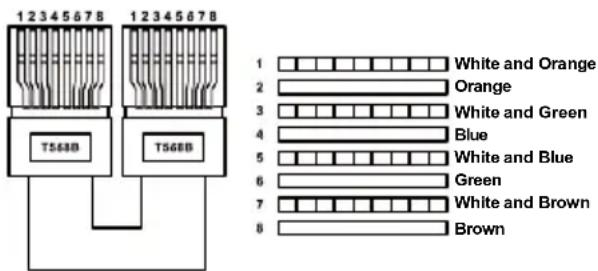
Direct Interconnection Method
Table of Contents
- Introduction....1
- Features....1
- Specifications....2
- Operation Controls and Functions .... 4
4.1 Switch Panel....4
4.2 HDBaseT Receiver Panel 6
4.3 IR Cable Pin Assignment....9 - IR Remote....9
- Web GUI User Guide....10
- Dante Web GUI User Guide....20
- RS-232 Control Command....23
- Connection Diagram....24
1. Introduction
This 5x1 seamless presentation switch features 3 HDMI inputs, 2 USB-C inputs (DP Alt mode, USB 2.0, 100M Ethernet and 60W charging), 1 HDMI output and 1 HDBT mirrored output. HDBT supports standard PoE power supply and can extend uncompressed signal up to a distance of 230ft/70m (4K@30Hz 4:4:4) or 131ft/40m (4K@60Hz 4:4:4) via a single CAT6A (F/FTP) cable. This 5x1 seamless presentation switch output supports single full screen or various Multiview display modes (Single/PIP/PBP/Triple/Quad). This product supports USB 2.0 local KVM switching and local Hub/HDBT USB pass-through function (from TX to RX). It also supports bi-directional RS-232 and IR control signal pass-through function.
This presentation switch is featured with 1 analog audio input, 1 analog audio output, and Dante 2x2 audio input and output. It built-in 3x3 audio matrix with independent audio EQ/volume/delay adjustment.
2. Features
HDCP 2.2 and DP 1.2 compliant
Support 18Gbps video bandwidth
Support video resolution up to 4K@60Hz 4:4:4, as specified in HDMI 2.0b
Uncompressed 4K60 over HDBT 3.0 up to 132ft/40m via single CAT6A (F/FTP) cable
Uncompressed 1080P&4K30 over HDBT 3.0 up to 230ft/70m via single CAT6A (F/FTP) cable
Up to 5 categories of Multiview display modes: Single/PIP/PBP/Triple/Quad
Support 5x1 seamless switching (single screen) and fast switching (Multiview) function
Input: 2x USB-C, 3x HDMI, 1x Analog audio, 1x Dante 2ch
Output: 1x HDMI and 1x HDBT mirrored, 1x Analog audio, 1x Dante 2ch
HDMI and HDBaseT (PoE) outputs (Mirrored)
Dante 2x2 audio input and output
USB-C supports DisplayPort Alt mode for A/V, USB 2.0, 100M Ethernet and 60W charging
Local USB 2.0 KVM switching and extending USB 2.0 over HDBT 3.0
Signal input supports manual switching and automatic switching modes
Support analog/Dante audio embedding, analog/Dante audio de-embedding output
CEC/RS-232 control external devices ON/OFF
Advanced EDID management
Flexible control via front panel buttons, IR remote, RS-232, TCP/IP or Web GUI
Package Contents
1 x 5x1 Seamless Presentation Switch
1 x HDBaseT Receiver
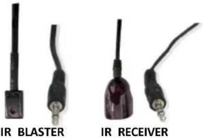
1 x IR Blaster Cable (1.5 meters)
1 x IR Wideband Receiver Cable (1.5 meters)
2 x 3pin-3.5mm Phoenix Connector (male)
3 x 5pin-3.5mm Phoenix Connector (male)
4 x Mounting Ear
8 x Machine Screw
1 x 24V/8A Desktop Power Supply & 1 x AC Power Cord (1.5 meters)
1 x IR Remote
- Specifications
| Technical | |
| HDMI Compliance | HDMI 2.0b |
| HDCP Compliance | HDCP 2.2 |
| DP Version | DP 1.2 |
| Video Bandwidth | 18Gbps |
| USB Bandwidth | TX USB DEVICES to TX HOST/USB-C: 480MbpsRX USB DEVICES to TX HOST/USB-C: 350MbpsRX USB DEVICES to RX HOST: 480Mbps |
| Network Bandwidth (LAN and USB-C Connection) | 100Mbps |
| Input Video Resolution | 4K2K@50Hz/60Hz 4:4:4, 4Kx2K@24/30Hz, 480i ~1080p50/60Hz. |
| Output Video Resolution | Auto, 3840x2160p60, 3840x2160p50, 4096x2160p60, 4096x2160p50, 3840x2160p30, 3840x2160p25, 1920x 1200p60RB, 1920x1080p60, 1920x1080p50, 1360x768p60, 1280x800p60, 1280x720p60, 1280x720p50, 1024x768p60 |
| IR Level | 12Vp-p |
| IR Frequency | Wideband 20K-60KHz |
| Color Depth | Input: 8/10/12-bit, 8-bit (4K60Hz 4:4:4)Output: 8-bit |
| Color Space | RGB, YCbCr 4:4:4 / 4:2:2, YUV 4:2:0 |
| Audio Formats | LPCM 2.0 |
| Audio Sample Rate | 48KHz |
| Transmission Distance | 1080P&4K30 -- 230ft/70m; 4K60 -- 131ft/40m |
| HDR | Input supports HDR, output does not support HDR. |
| ESD Protection | Human-body Model: ±8kV (Air-gap discharge), ±4kV (Contact discharge) |
| TX Analog Audio | |
| Input Impedance | 10K Ohms |
| Output Impedance | 330 Ohms |
| Line Input Level (Maximum) | 8.2dBu (2Vrms) @ balanced or unbalanced audio |
| Line Output Level (Maximum) | 8.2dBu (2Vrms) @ balanced audio2.2dBu (1Vrms) @ unbalanced audio |
| Frequency Response | (+0.5 dB, -1 dB) 20 Hz to 20 kHz |
| Audio Output Sync Delay | 0 to 50ms |
| Audio S/N Ratio | 93dB @ 2Vrms, 1kHz A-weighted |
| Audio THD+N | <0.1% @ 0dBV, 1kHz |
| RX Analog Audio | |
| Output Impedance | 330 Ohms |
| Line Output Level (Maximum) | 8.2dBu (2Vrms) @ balanced audio2.2dBu (1Vrms) @ unbalanced audio |
| Frequency Response | (+0.5 dB, -1 dB) 20 Hz to 20 kHz |
| Audio Output Sync Delay | 0 to 50ms |
| Audio S/N Ratio | 93dB @ 2Vrms, 1kHz A-weighted |
| Audio THD+N | <0.1% @ 0dBV, 1kHz |
| Dante Audio | |
| Audio Formats | LPCM2.0 |
| Sample Rate | 44.1, 48, 88.2 and 96KHz at 24 bits |
| Audio Delay | 2ms, 3ms, 4ms, 5ms, 10ms |
| Network Bandwidth | 100Mbps |
| Connection | |
| Transmitter | Input: 3 x HDMI INPUT [Type A, 19-pin female]2 x USB-C [24-pin female]1 x LINE IN [5pin-3.5mm phoenix connector]1 x DANTE [RJ45]Output: 1 x HDMI OUTPUT [Type A, 19-pin female]1 x HDBT OUTPUT [RJ45]1 x LINE OUT [5pin-phoenix connector]Control: 1 x RS-232 [3pin- phoenix connector]1 x LAN [RJ45]1 x USB HOST [USB Type B]2 x USB DEVICES [USB Type A]1 x IR IN [3.5mm stereo mini-jack]1 x IR OUT [3.5mm stereo mini-jack] |
| Receiver | Input: 1 x HDMI IN [Type A, 19-pin female]1 x HDBaseT IN [RJ45]Output: 1 x HDMI OUT [Type A, 19-pin female]1 x LINE OUT [5pin- phoenix connector]Control: 1 x RS-232 [3pin-phoenix connector]1 x USB HOST [USB Type B]2 x USB DEVICES [USB Type A]1 x SERVICE [Micro USB]1 x IR IN [3.5mm stereo mini-jack]1 x IR OUT [3.5mm stereo mini-jack] |
| Mechanical | |
| Housing | Front panel: Aluminum; Rear case: Metal Enclosure |
| Color | Black |
| Dimensions | Transmitter: 220mm [W]×150mm [D]×44mm [H]Receiver: 140mm [W]×105mm [D]×21.5mm [H] |
| Weight | Transmitter: 1.21Kg; Receiver: 424g |
| Power Supply | Input: AC100 - 240V 50/60HzOutput: DC 24V/8A (US/EU standard, CE/FCC/UL certified) |
| Power Consumption | 150W (Max) |
| Operating Temperature | 0°C ~ 40°C / 32°F ~ 104°F |
| Storage Temperature | -20°C ~ 60°C / -4°F ~ 140°F |
| Relative Humidity | 20%~90% RH (non-condensing) |
4. Operation Controls and Functions
4.1 Switch Panel
Front Panel
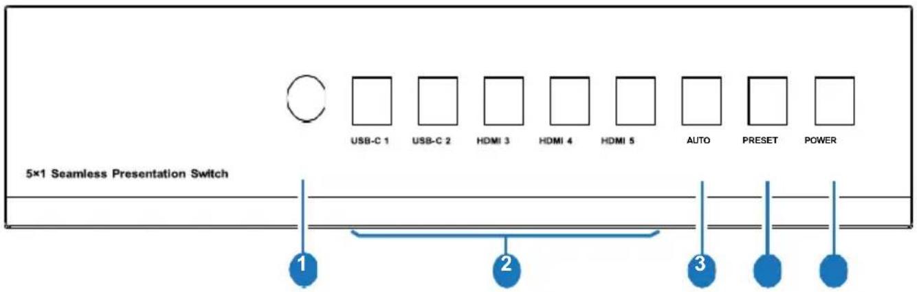
| No. | Name | Function Description |
| 1 | IR Window | IR signal receiving window, receiving the IR remote signal. |
| 2 | USB-C 1 /USB-C 2 /HDMI 3 / HDMI 4 /HDMI 5 buttons | In single screen display mode, press the USB-C 1 / USB-C 2 / HDMI 3 / HDMI 4 / HDMI 5 button to select the signal input channel, and the corresponding button light will be on.In Multiview mode, input button lights indicate the outputs, for example, when USB-C 1, HDMI 3 and HDMI 5 port are the signal /input channels for triple display mode, the corresponding USB-C 1, HDMI 3 and HDMI 5 button lights will be on. When USB-C 1 port is the shared signal input channel for triple display mode, only the corresponding USB-C 1 button light will be on.It can be set through the Web GUI. Press any input button will switch back to the single screen display mode. The button light will turn off automatically after 1 second each time. |
| 3 | AUTO button | Press this button to enable/disable the auto switching function. When the auto switching function is enabled, the button light will be on. |
| 4 | PRESET button | Press this button to cycle through the preset application scenes. The button light will automatically turn off after 1 second each time. The scenes can be preset through the Web GUI. |
| 5 | POWER button | Press and hold this button for 3 seconds, the product will enter standby mode, and the button light will be on. In standby mode, short press this button, the product will be turned on and the button light will be off. |
Rear Panel
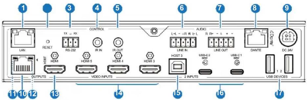
| No. | Name | Function Description |
| 1 | LAN port | Connect to a router or Switch for USB-C Internet access or Web GUI control. |
| 2 | RESET button | Press and hold this button for 5 seconds to restore to factory default settings. |
| 3 | RS-232 port | RS-232 serial port, used for RS-232 signal pass-through or controlling this product via RS-232 commands. |
| 4 | IR IN port | Connect the IR receiver cable, used for IR signal pass-through or controlling this product via the IR remote. |
| 5 | IR OUT port | Connect the IR blaster cable, the IR signal is from the IR IN port of the HDBaseT Receiver. |
| 6 | LINE IN port | Analog audio input port, supporting balanced/unbalanced audio input, with a maximum support of 2Vrms.Balanced connection method: L+, L-, 12 , R+, R-Unbalanced connection method: L+, 12 , R+ |
| 7 | LINE OUT port | Analog audio output port, supporting balanced audio output (with a maximum support of 2Vrms) and unbalanced audio output (with a maximum support of 1Vrms).Balanced connection method: L+, L-, 12 , R+, R-Unbalanced connection method: L+, 12 , R+ |
| 8 | DANTE port | Dante Network port, connected to the Switch with other Dante receivers. This port supports receiving and transmitting signals. |
| 9 | DC 24V port | Power port, connected to the DC 24V power adapter. |
| 10 | HDBT OUTPUT port | HDBaseT output port, connected to the HDBaseT IN port of the receiver with a CAT6A (F/FTP) cable. |
| 11 | Data Signal Indicator (Yellow) | Light on: HDMI signal input with HDCP.Light flashing: HDMI signal input without HDCP.Light off: No HDMI signal input. |
| 12 | Link Signal Indicator (Green) | Light on: Transmitter and Receiver are in good connection status.Light flashing: Transmitter and Receiver are in poor connection status.Light off: Transmitter and Receiver are not connected. |
| 13 | HDMI OUTPUT port | HDMI signal output port, connected to HDMI display device such as TV or monitor with HDMI cable. |
| 14 | HDMI 3/4/5VIDEO INPUTS | HDMI signal input ports, connected to HDMI source device such as DVD, PC or Blu-ray player with HDMI cable. |
| 15 | HOST 3 port | USB Host port, connected to PC assigned with HDMI 3. |
| 16 | USB-C 1/2 ports | USB-C signal input port, connected to USB-C signal source device, this port has USB C Alt Mode video and USB ability with the function of 60W charging. |
| 17 | USB DEVICES ports | Two USB extension ports, connected to mouse, keyboard, USB camera or other USB devices. |
4.2 HDBaseT Receiver Panel
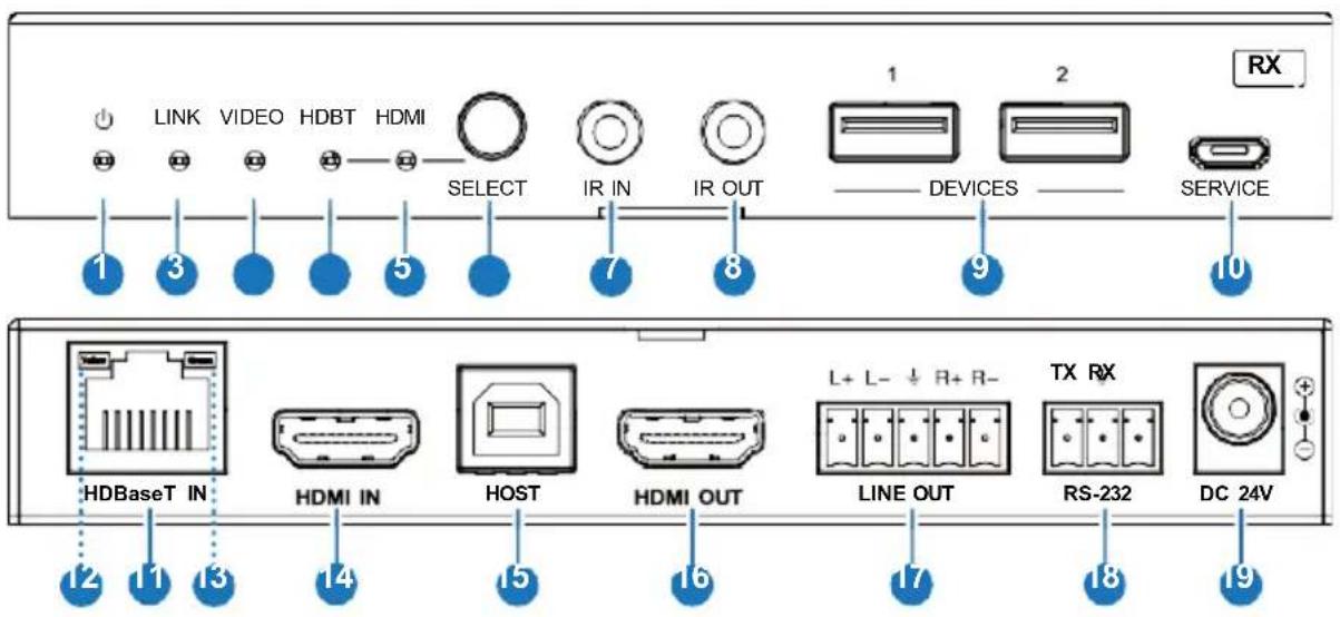
| No. | Name | Function Description |
| 1 | Power LED | When the receiver is powered on, the red power LED will be on. |
| 2 | LINK LED | Light on: Transmitter and Receiver are in good connection status.Light flashing: Transmitter and Receiver are in poor connection status.Light off: Transmitter and Receiver are not connected. |
| 3 | VIDEO LED | Light on: HDMI signal input with HDCP.Light flashing: HDMI signal input without HDCP.Light off: No HDMI signal input. |
| 4 | HDBT LED | When the HDBaseT IN port is selected as the signal input channel, the green HDBT LED will be on. |
| 5 | HDMI LED | When the HDMI IN port is selected as the signal input channel, the green HDMI LED will be on. |
| 6 | SELECT button | Press this button to select signal input channel. |
| 7 | IR IN port | Connect the IR receiver cable, the IR signal will be sent to the IR OUT port of the transmitter. |
| 8 | IR OUT port | Connect the IR blaster cable, the IR signal is from the IR IN port of the transmitter. |
| 9 | DEVICES ports | Two USB extension ports, connected to whiteboard, mouse, keyboard, USB camera or other USB devices. |
| 10 | SERVICE port | Firmware update port. |
| 11 | HDBaseT IN port | HDBaseT input port, connected to the HDBT OUTPUT port of the transmitter with a CAT6A (F/FTP) cable. |
| 12 | Data Signal Indicator (Yellow) | Light on: HDMI signal input with HDCP.Light flashing: HDMI signal input without HDCP.Light off: No HDMI signal input. |
| 13 | Link Signal Indicator (Green) | Light on: Transmitter and Receiver are in good connection status.Light flashing: Transmitter and Receiver are in poor connection status.Light off: Transmitter and Receiver are not connected. |
| 14 | HDMI IN port | HDMI signal input port, connected to HDMI source device such as DVD or Blu-ray player with HDMI cable. |
| 15 | HOST port | USB Host port, connected to PC. |
| 16 | HDMI OUT port | HDMI signal output port, connected to HDMI display device such as TV or monitor with HDMI cable. |
| 17 | LINE OUT port | Analog audio output port, supporting balanced audio output (with a maximum support of 2Vrms) and unbalanced audio output (with a maximum support of 1Vrms).Balanced connection method: L+, L-, ±, R+, R-Unbalanced connection method: L+, ±, R+ |
| 18 | RS-232 port | RS-232 serial port, used for RS-232 signal pass-through or controlling this receiver via RS-232 commands. |
| 19 | DC 24V port | Power port, connected to the DC 24V power adapter.Note: The receiver also can be powered by HDBT POE power (from the HDBaseT IN port of the TX unit). |
4.3 IR Cable Pin Assignment
The pin assignment of the IR Receiver cable and IR Blaster cable is as below:
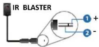
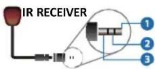
IR Signal Grounding Power 12V
Note: When the angle between the IR receiver and the remote control is ± 45^ , the transmission distance is 0-5 meters; when the angle between the IR receiver and the remote control is ± 90^ , the transmission distance is 0-8 meters.
5. IR Remote

① Power button: Press this button to power on the switch or set it to standby mode.
② VIDEO buttons:
USB-C 1 / USB-C 2 / HDMI 3 / HDMI 4 / HDMI 5: Press these buttons to select input source in single screen display mode, and the corresponding input button light on the front panel will light in blue.
◀▶: Press these buttons to circularly select the last or next input source in single screen display mode.
AUTO: Press this button to enable/disable the auto switching function.
PRESET: Press this button to cycle through the preset application scenes.
: Multiview display mode switching button. Short press this button to circularly select: Single - PIP - PBP-Triple - Quad.
RES.: Press this button to cycle through the output resolution.
FREEZE: Press this button to freeze/unfreeze the screen.
RX HDBT: Press this button to select the HDBaseT IN port as the signal source input channel of the receiver.
RX HDMI: Press this button to select the HDMI IN port as the signal source input channel of the receiver.
③ AUDIO buttons:
USB-C 1 / USB-C 2 / HDMI 3 / HDMI 4 / HDMI 5 / WIN 1 / AIN /
DANTE: Press these buttons to select the audio input channel for the HDMI/HDBT output.
Note: USB-C 1, USB-C 2, HDMI 3, HDMI 4, HDMI 5 and WIN 1 belongs to the audio input channels of Main In (HDMI/USB-C In).
Mute: Press this button to mute / unmute the audio of Master Out.
VOL-, VOL+: Press these buttons to increase / decrease the audio f er t.
6. Web GUI User Guide
The presentation switch can be controlled by Web GUI. The operation method is shown as below:
Step 1: Get the current IP Address.
The default IP address is a static address 192.168.1.100 Port: 8000 by default. You can get the current switch IP address via RS-232 command control. Send the ASCII command "r ip addr" through a Serial Command tool (Putty or Hercules), then you'll get the current IP address (The IP address is variable, depending on what the specific status it is in).
For the details of RS-232 control, please refer to "Section 9. RS-232 Control Command".
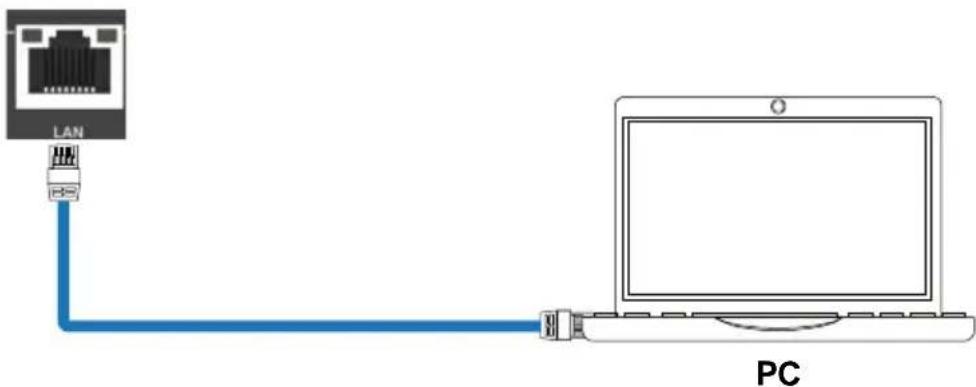
Step 2: Connect the LAN port of the presentation switch to a PC with an UTP cable (as shown in the below figure) and set the IP address of the PC to be in the same network segment with the presentation switch.
Step 3: Input the current IP address of switch into your browser on the PC to enter Web GUI interface.

After entering the Web GUI page, there will be a Login interface, as shown below:
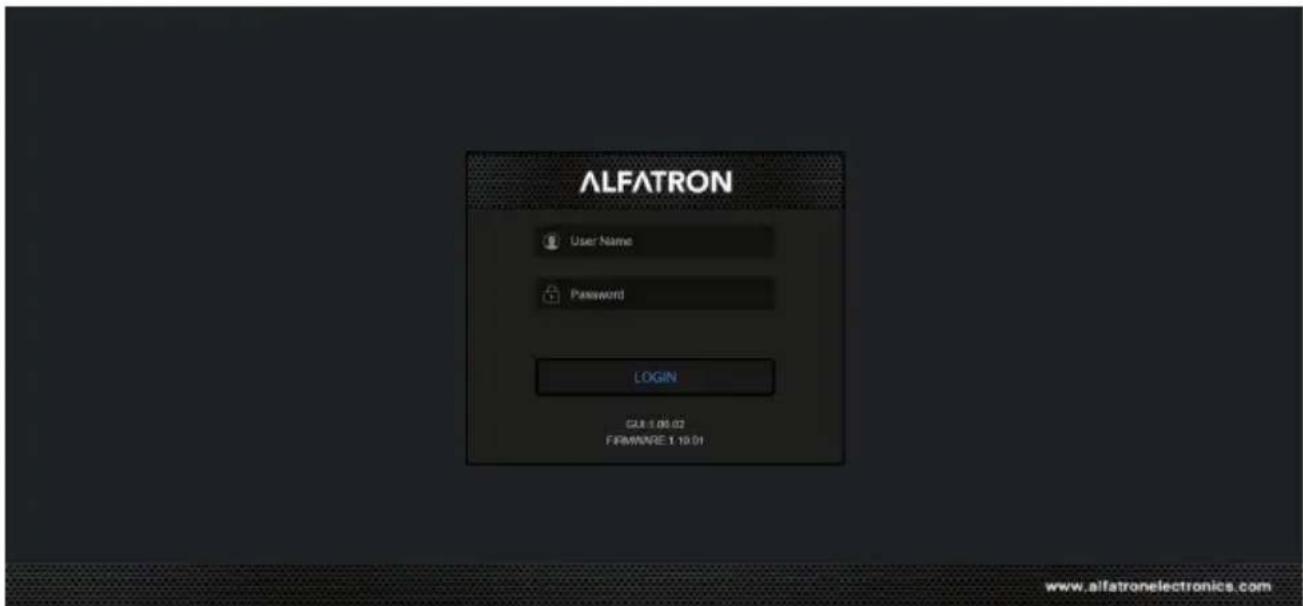
The default Admin username and password is as below:
| Username | User | Admin |
| Password | user | admin |
USER password:
Select the username "User" and input the password "user", then click the "LOGIN" button to enter the User page.
■ User Page
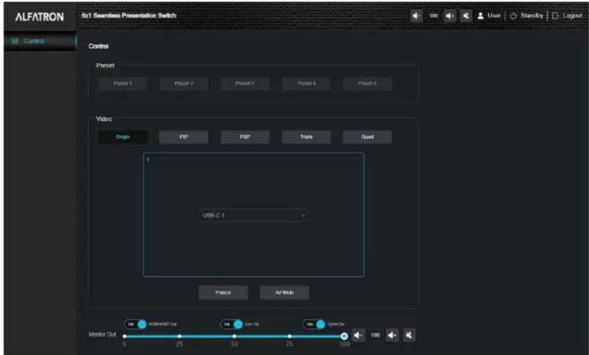
You can do the following operations on the User page:
① Preset: Recall the preset application scenes.
② Video: Set the Multiview display mode, select input source for each screen, freeze the screen or mute the audio.
③ Master Out: Set the audio volume or mute/unmute the audio for Master Out. You can respectively turn on/off the HDMI/HDBT Out, Line Out or Dante Out.
In the Login interface, select the username "Admin" and input the password "admin", then click the "LOGIN" button to enter the Information page of the admin interface.
■ Information Page
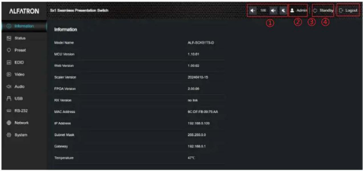
The Information page provides basic information about the model's name, software version, IP information and the current machine temperature.
Besides, you can do the following operations in the upper right corner of each page.
① Display and set the audio volume of Master Out. Click the volume icons to increase/decrease the audio volume of Master Out or click the mute icon to mute/unmute the audio of Master Out. When muted, the mute icon displays red.
② Display the current username (User or Admin).
③ Click the power icon to power on the switch or set it in standby mode.
④ Click the logout icon to logout and return to the login interface.
■ Status Page
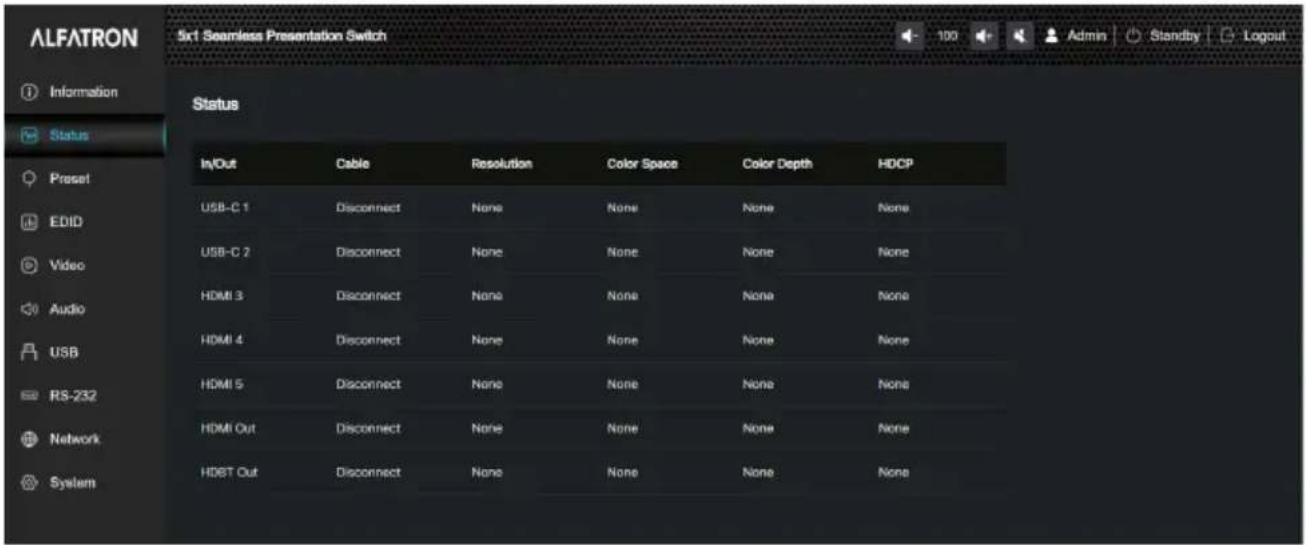
The Status page displays the input & output port connection status, input & output resolution, Color Space, Color Depth and HDCP.
■ Preset Page
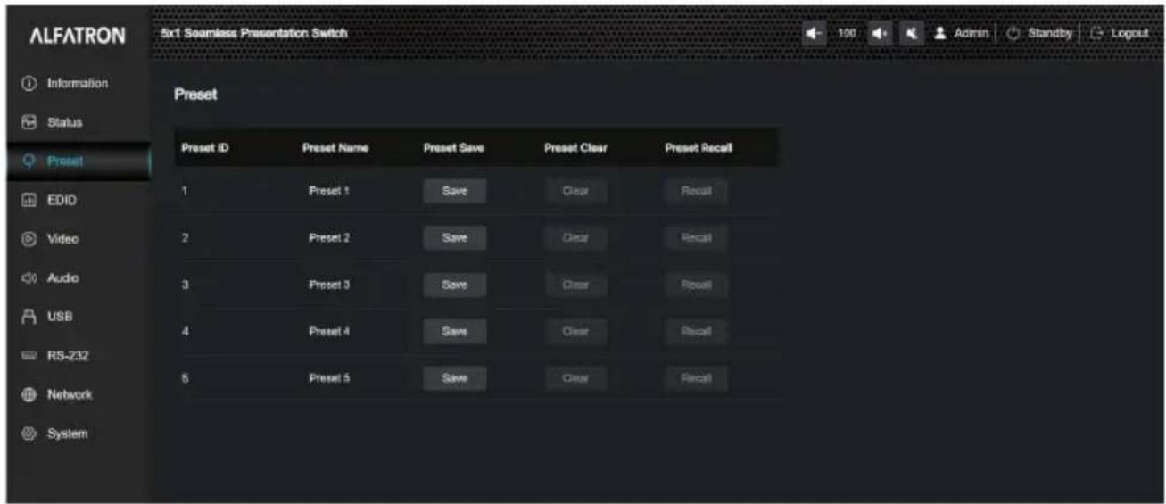
You can set up to 5 preset scenes on the Preset page.
① Preset Name: You can name the preset scene. (Chinese name is not supported.)
② Preset Save: Click the Save button to save the scene.
③ Preset Clear: Click the Clear button to clear the saved scene.
④ Preset Recall: Click the Recall button to recall the saved scene.
■ EDID Page
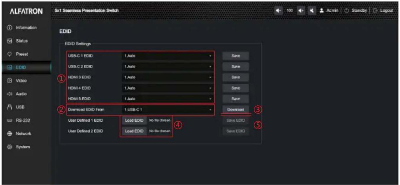
You can do the following operations on the EDID page.
① Click the drop-down list to set EDID for each input port. The EDID list is as below.
| No. | EDID Mode | No. | EDID Mode |
| 1 | Auto | 9 | 1680x1050, Stereo Audio 2.0 |
| 2 | Copy HDMI OUT | 10 | 1600x1200, Stereo Audio 2.0 |
| 3 | Copy HDBT OUT | 11 | 1440x900, Stereo Audio 2.0 |
| 4 | 4K2K60_444, Stereo Audio 2.0 | 12 | 1360x768, Stereo Audio 2.0 |
| 5 | 4K2K30_444, Stereo Audio 2.0 | 13 | 1280x1024, Stereo Audio 2.0 |
| 6 | 1080P, Stereo Audio 2.0 | 14 | 1024x768, Stereo Audio 2.0 |
| 7 | 720P, Stereo Audio 2.0 | 15 | User Defined 1 |
| 8 | 1920x1200, Stereo Audio 2.0 | 16 | User Defined 2 |
② Click the drop-down list to select USB-C 1\USB-C 2\HDMI 3\HDMI 4\HDMI 5\HDMI OUT\HDBT OUT for EDID download.
③ Click the Download button to download EDID and generate a .bin file.
④ Click the Load EDID button to download user-defined EDID. Please note that only (.bin) files are supported.
⑤ Click the Save EDID button to save the user-defined EDID.
■ Video Page
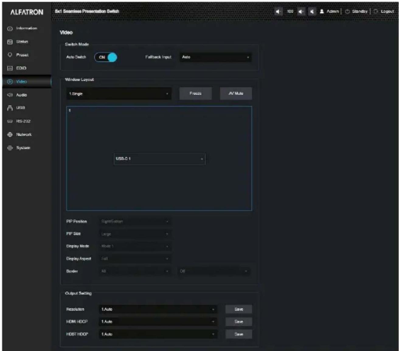
Switch Mode
① Auto Switch: You can turn on/off the auto switching function.
② Fallback Input: Click the drop-down list to select Auto\USB-C 1\USB-C 2\HDMI 3\HDMI 4\HDMI 5 as the signal source of Fallback input. When the auto switching function is turned on and the current input source is disconnected, the Fallback input signal source will be selected automatically. When the Fallback input is set to be Auto, the switch will detect and switch to the signal with the auto switching sequence of USB-C 1>USB-C 2->HDMI 3->HDMI 4->HDMI 5.
Note: The auto switching function is available only in single screen display mode.
Window layout
① Window layout: Click the drop-down list to select the display mode (1.Single\2.PIP\3.PBP\4.Triple\5.Quad).
② Freeze: You can freeze the screen.
③ AV Mute: You can mute the audio and video.
④ PIP Position: Click the drop-down list to select the display position in PIP display mode.
⑤ PIP Size: Click the drop-down list to select the display size in PIP display mode.
⑥ Display Mode: Click the drop-down list to select the display mode in PBP\Triple\Quad display mode.
⑦ Display Aspect: Click the drop-down list to select the display aspect in PBP\Triple\Quad
display mode.
⑧ Border: Click the drop-down list to select the border and border color in PBP\Triple\Quad display mode.
Output Setting
① Resolution: Click the drop-down list to select the output resolution. The output resolution list is as following.
| No. | Output Resolution | No. | Output Resolution |
| 1 | Auto | 9 | 1920x1080p60 |
| 2 | 3840x2160p60 | 10 | 1920x1080p50 |
| 3 | 3840x2160p50 | 11 | 1360x768p60 |
| 4 | 4096x2160p60 | 12 | 1280x800p60 |
| 5 | 4096x2160p50 | 13 | 1280x720p60 |
| 6 | 3840x2160p30 | 14 | 1280x720p50 |
| 7 | 3840x2160p25 | 15 | 1024x768p60 |
| 8 | 1920x1200p60RB |
Note: When the output resolution is set to Auto, the switch will output the matching resolution based on the EDID of the back-end TV.
② HDMI HDCP: Click the drop-down list to select the HDMI HDCP version.
③ HDBT HDCP: Click the drop-down list to select the HDBT HDCP version. After setting up, click "Save" to take effect.
■ Audio Page
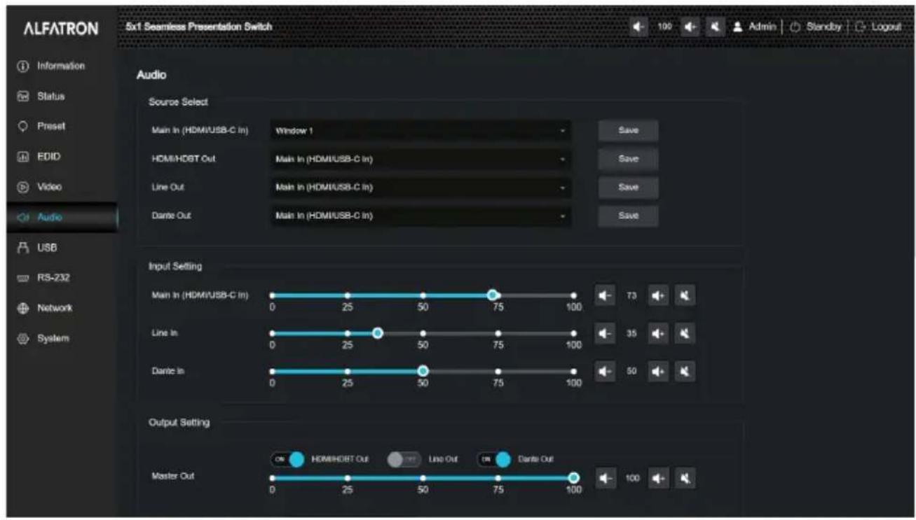
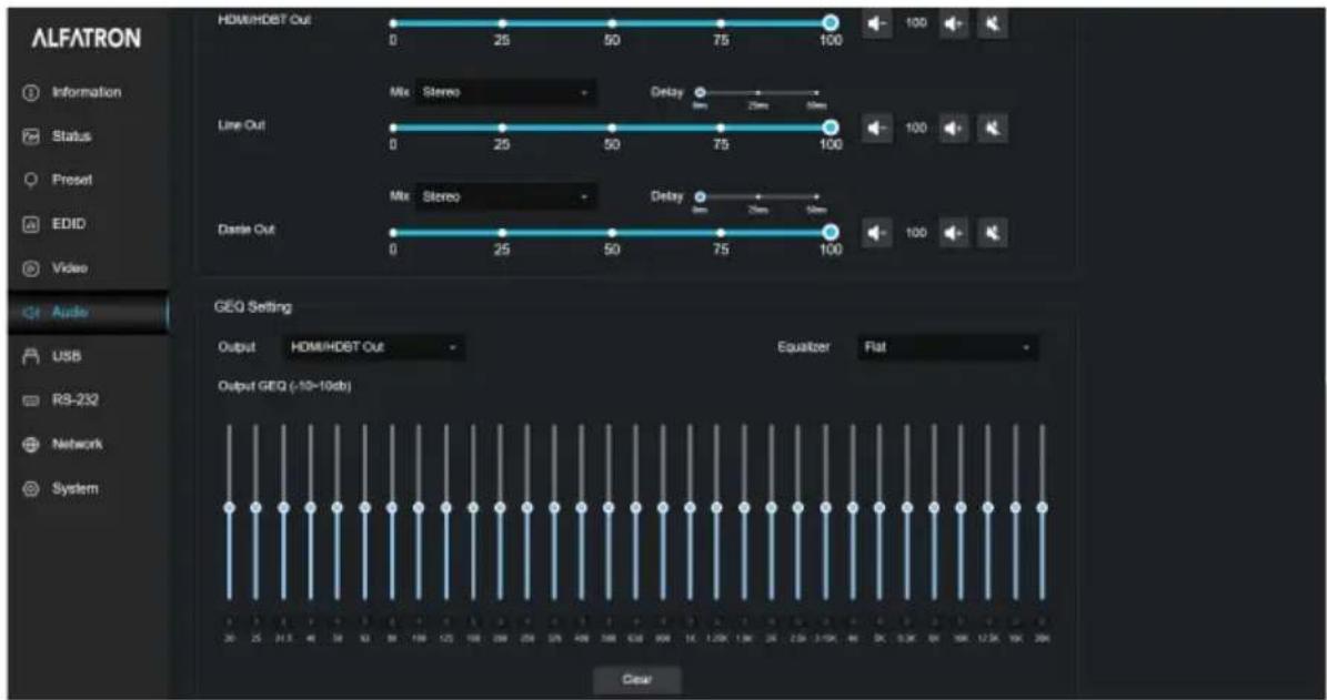
Source Select
① Main In: Click the drop-down list to select the signal source for Main In.
② HDMI/HDBT Out: Click the drop-down list to select the signal source for HDMI/HDBT Out.
③ Line Out: Click the drop-down list to select the signal source for Line Out.
④ Dante Out: Click the drop-down list to select the signal source for Dante Out.
After setting up, click "Save" to take effect.
Input Setting: You can respectively set the output volume or mute/unmute the audio for Main In (HDMI/USB-C In) \Line In\Dante In.
Output Setting
① Master Out: You can respectively set the output volume or mute/unmute the audio for HDMI/HDBT Out\Line Out\Dante Out or set together when turning on three options synchronously.
② HDMI/HDBT Out\Line Out\Dante Out: Click the drop-down list of Mix to select the audio output channel for the HDMI\HDBT Out\Line Out\Dante Out. You can set the delay, increase/decrease the audio or mute/unmute the audio.
GEQ Setting
① Output: Click the drop-down list to select the output channel.
② Equalizer: Click the drop-down list to set the equalizer.
Flat: Set all EG to 0db.
Custom1: Set EQ for custom 1.
Custom2: Set EQ for custom 2.
Custom3: Set EQ for custom 3.
Custom4: Set EQ for custom 4.
Custom5: Set EQ for custom 5.
■ USB Page
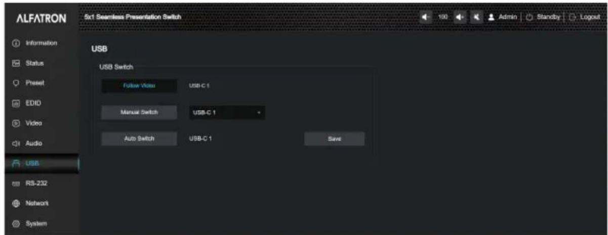
USB Switch
① Follow Video: Click this button to set the USB transmission to follow the video. It will follow the video output of window 1 in Multiview mode.
② Manual Switch: Switch to USB-C 1\USB-C 2\Host 3 manually.
③ Auto Switch: Detect and switch to USB-C 1\USB-C 2\Host 3 automatically.
After setting up, click "Save" to take effect.
■ RS-232 Page
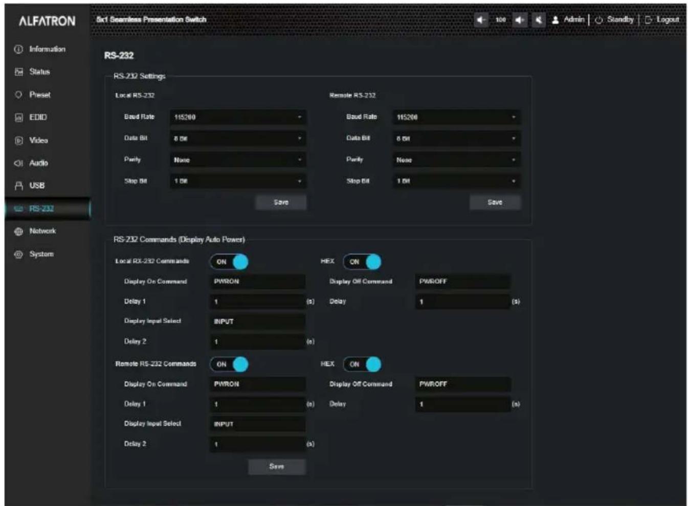
RS-232 Settings
① Local RS-232: You can set the Baud Rate, Data Bit, Parity and Stop Bit for the RS-232 port of the transmitter.
② Remote RS-232: You can set the Baud Rate, Data Bit, Parity and Stop Bit for the RS-232 port of the receiver.
RS-232 Commands (Display Auto Power)
① Local/Remote RS-232 Commands: You can turn on/off the local/remote RS-232 commands and hex.
② Display On/Off Command: You can input the display on/off command of the device.
③ Delay 1: You can set the delay time for the next action (such as send the Display Input Select command).
④ Display Input Select: You can input the command of switching the input channel for the display device.
⑤ Delay 2: You can set the delay time for the next action after sending the Display Input Select command.
After setting up, click "Save" to take effect.
■ Network Page
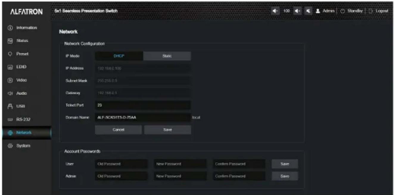
① Network Configuration: You can set the IP Mode (DHCP/Static), IP Address, Subnet Mask, Gateway, Telnet Port and Domain Name.
Note: The Domain Name "ALF-SCK51TS-D-75AA.local" can be used to login the Web GUI.
② Account Passwords: You can modify the login password for User and Admin. After setting up, click "Save" to take effect.
■ System Page
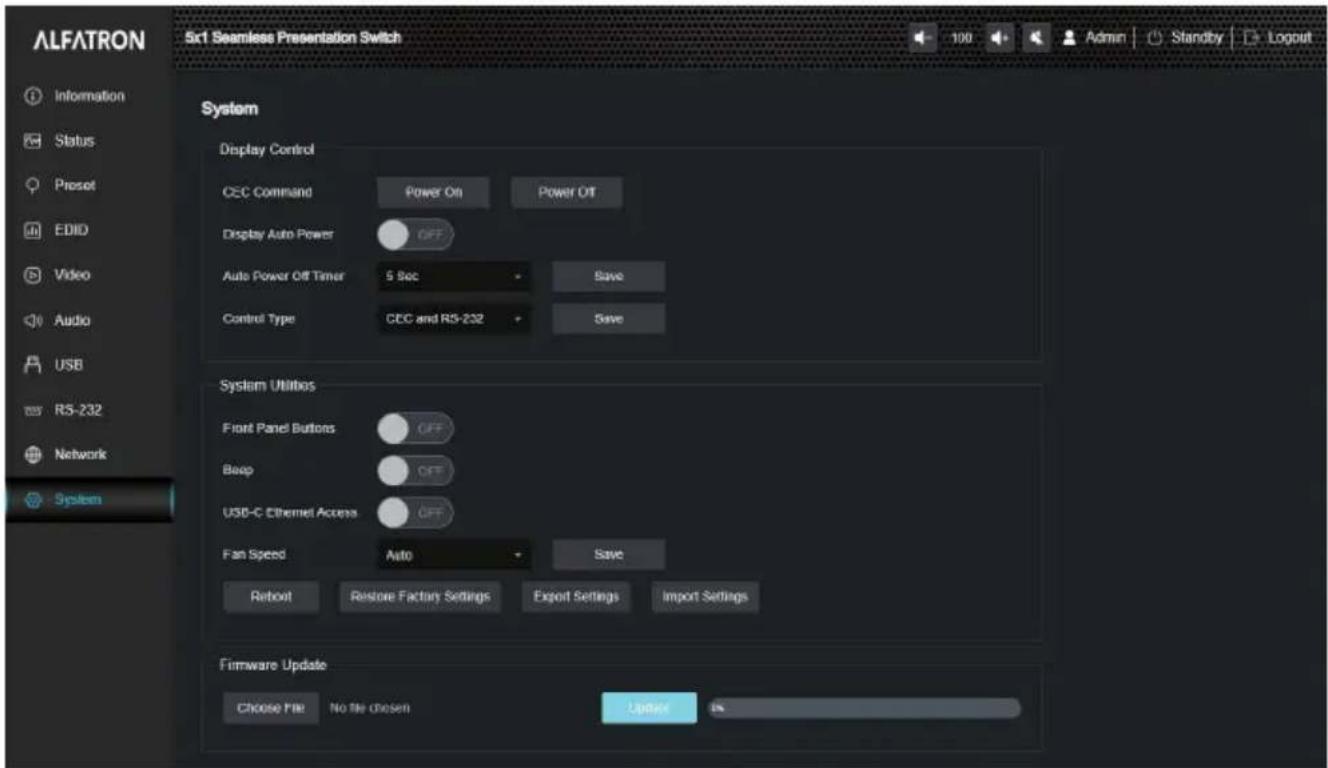
Display Control
① CEC Command: You can power on/off the CEC command.
② Display Auto Power: You can turn on/off the Display Auto Power. When it is set to ON, you can control the display device power on/off or switch the port based on the power status (power on/standby) or the signal input status of the transmitter by sending serial port or CEC
Power On/Off command.
③ Auto Power off Timer: Click the drop-down list to select the delay time for sending the command to turn off the display device when the transmitter is in standby mode or there is no signal input.
④ Control Type: Click the drop-down list to select the control type.
System Utilities
① Front Panel Buttons: Click "ON/OFF" to lock/unlock panel buttons. "On" indicates that panel buttons are available; "OFF" indicates panel buttons are unavailable.
② Beep: Click "ON/OFF" to turn on/off the beep.
③ USB-C Ethernet Access: Click "ON/OFF" to turn on/off the Ethernet access function of USB-C.
④ Fan Speed: Click the drop-down list to set the fan speed.
⑤ Reboot: Click "Reboot" to reboot the switch.
⑥ Restore Factory Settings: Click this button to restore the switch to factory settings.
⑦ Export Settings: Click this button to export configuration files.
⑧ Import Settings: Click this button to import configuration files.
Firmware Update: You can update the software of MCU, Web, Scaler or receiver. Click "Choose File" to select the update file, then click "Update" to start update. When the progress bar reaches 100%, the update is complete.
7. Dante Web GUI User Guide
There is a built-in Dante Web GUI for the presentation switch. The operation method is shown as below:
Step 1: Connect the presentation switch and PC to the same Ethernet Switch with two Network cables.
Step 2: Set the Network connection setting of PC to be "Obtain an IP address Automatically".
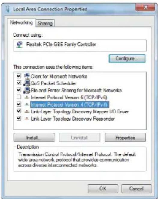
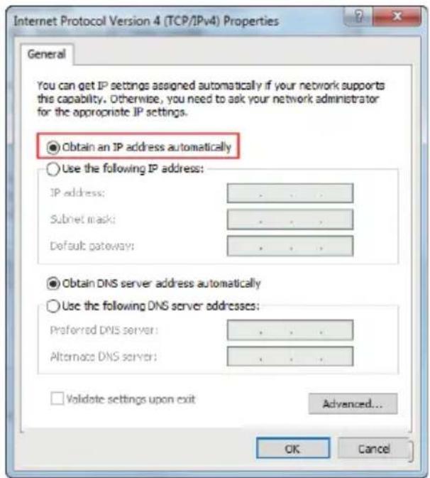
Step 3: Open the Dante Controller software on the PC, and find the Dante device on the Routing page, as shown in the figure below.
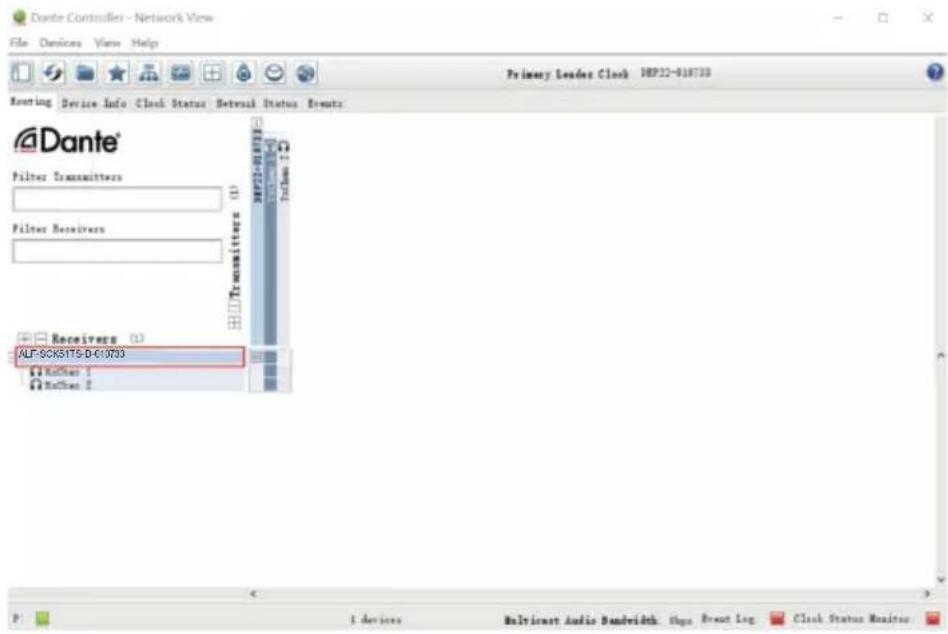
Step 4: Click the Device Info tab to check the IP address of the Dante device.
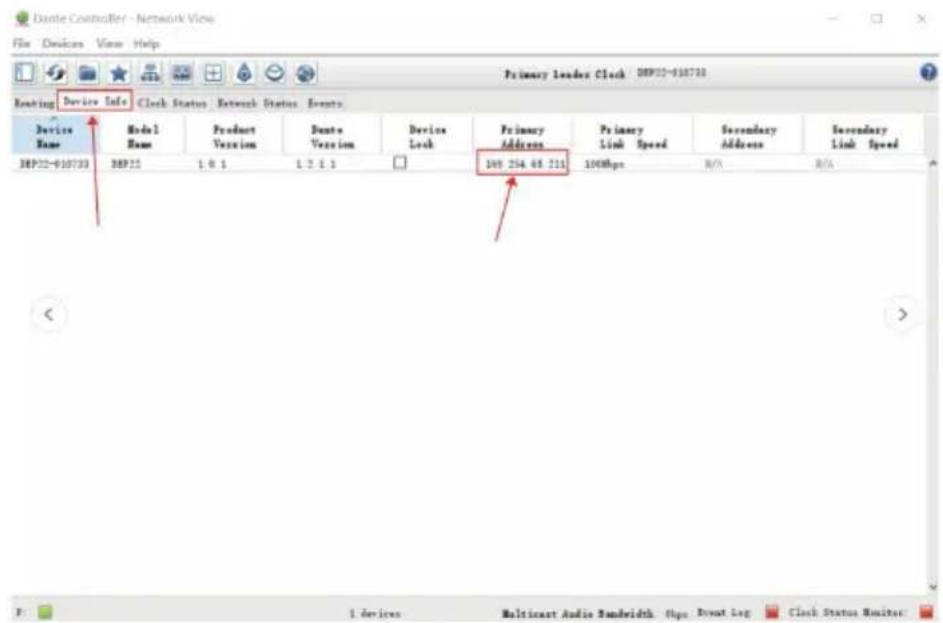
Step 5: Input the IP address of Dante device into your browser on the PC to enter the login interface of the Dante Web GUI.
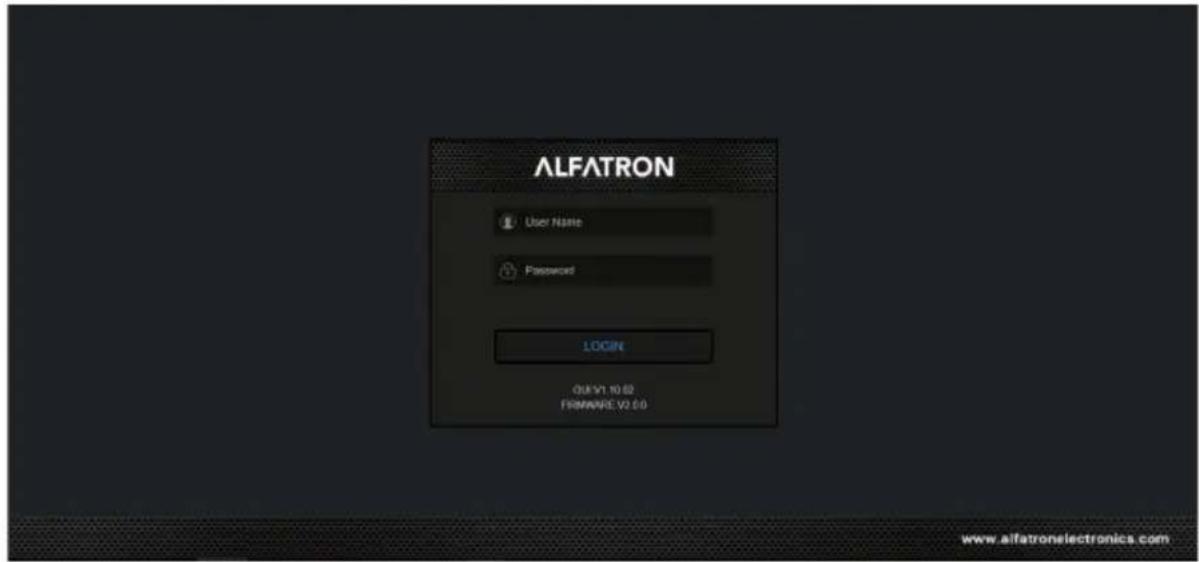
Step 6: Select the default username "Admin" and input the password "admin", then click the "LOGIN" button to enter the Information page of Dante Web GUI.
■ Information Page
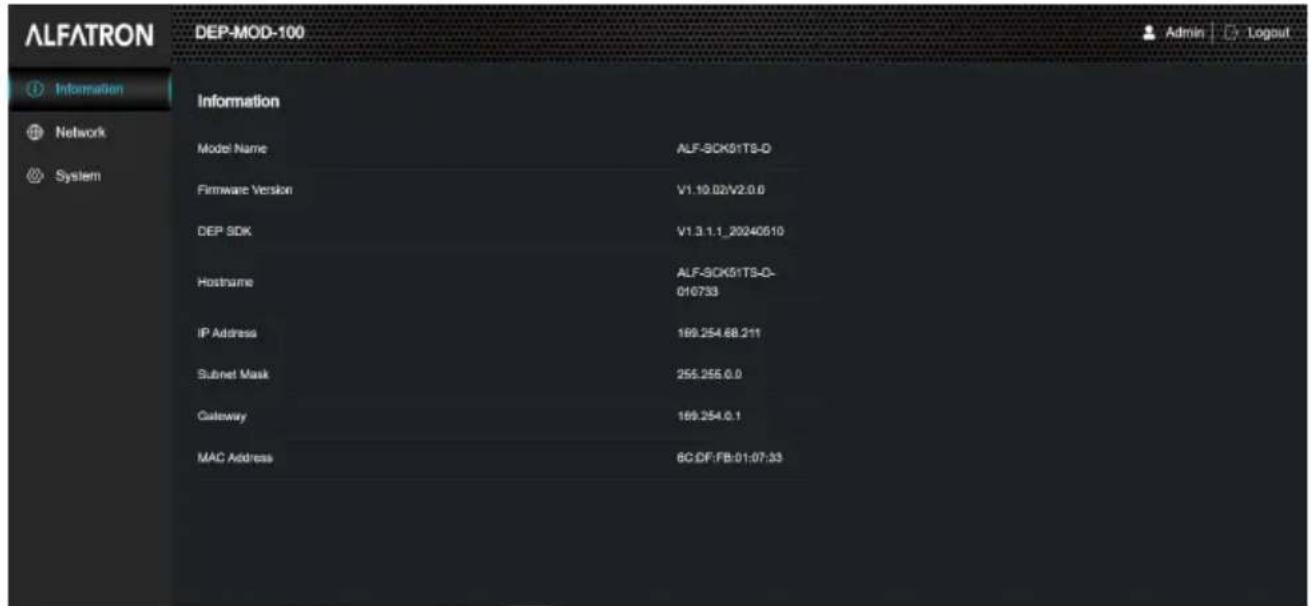
The Information page provides basic information about the model's name, software version and IP information.
■ Network Page
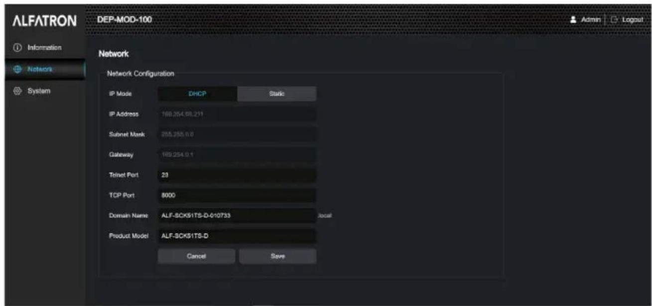
On the Network page, you can set the IP Mode (DHCP/Static), IP Address, Subnet Mask, Gateway, Telnet Port, TCP Port and Domain Name. The product model can be modified. Note: The Domain Name "ALF-SCK51TS-D-010733.local" can be used to login the Dante Web GUI.
■ System Page
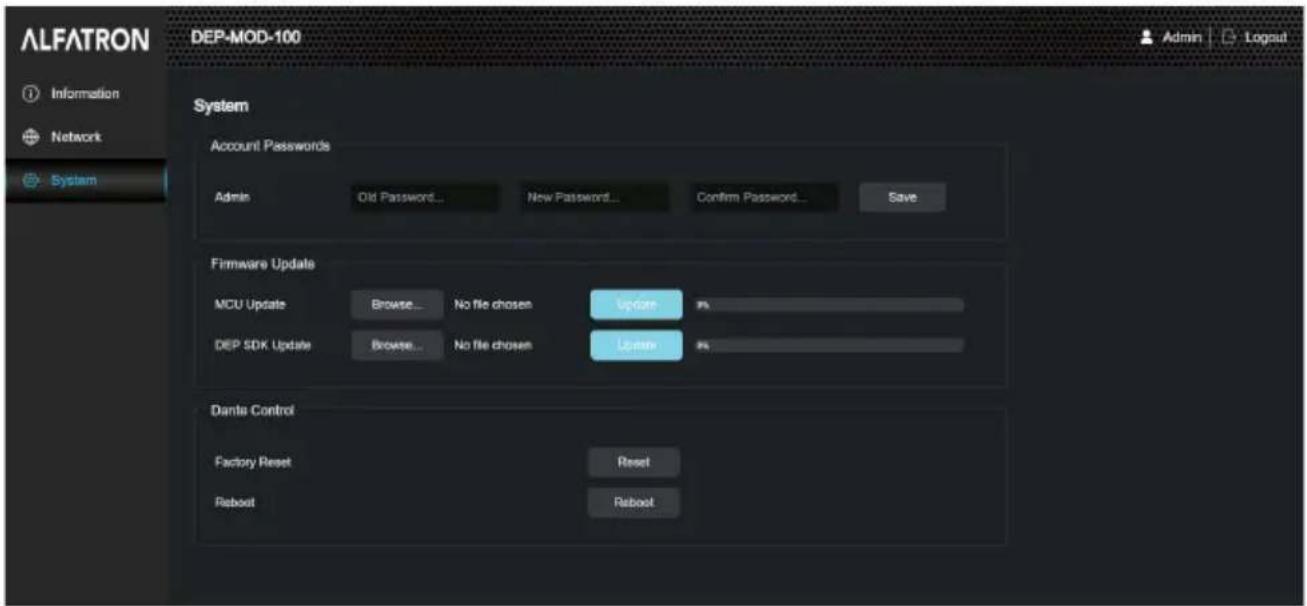
You can do the following operations on the System page:
① Account Passwords: You can modify the login password for Admin. After inputting the old password, new password and confirm password, click "Save" to take effect.
② Firmware Update: You can update the firmware and DEP SDK software. Click “Browse” to select the update file, and then click “Update”. When the progress bar reaches 100%, the update is complete.
③ Dante Control: Click "Reset" to restore to factory settings. Click "Reboot" to reboot the device.
8. RS-232 Control Command
The product also supports RS-232 command control. Connect the RS-232 port of the product to a PC with a 3-pin phoenix connector cable and an RS-232 to USB cable. The connection method is as follows.
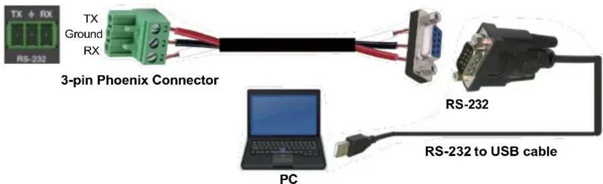
Then open a Serial Command tool on PC to send ASCII commands to control the product. The ASCII command list about the product is shown as below.
API GUIDE IS AVAILABLE IN A SEPARATE DOCUMENT.
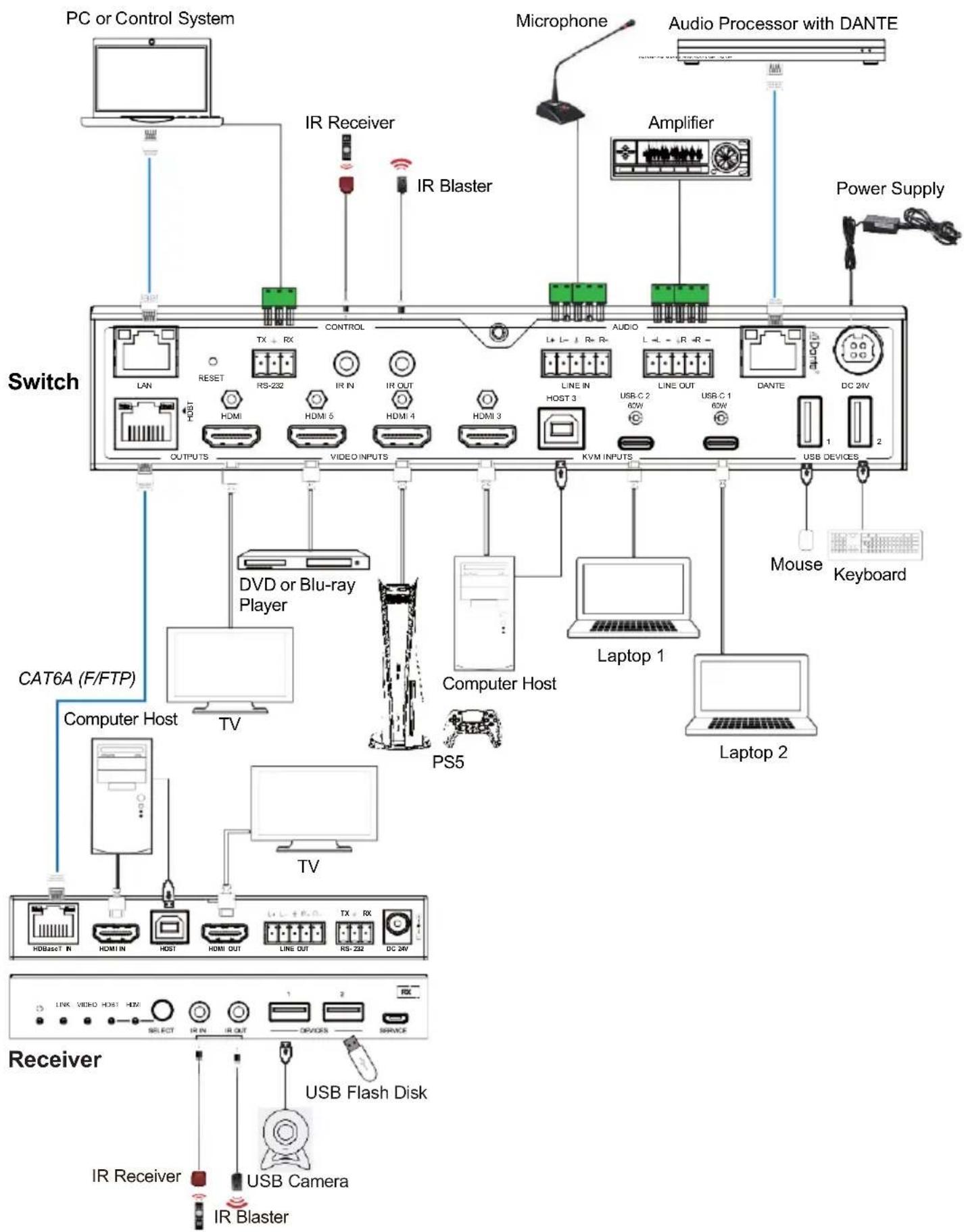
9. Connection Diagram
- Thank you for purchasing this product
- Surge protection device recommended
- Caution
- Table of Contents
- Introduction
- Features
- Package Contents
- Operation Controls and Functions
- Switch Panel
- HDBaseT Receiver Panel
- IR Cable Pin Assignment
- IR Remote
- Web GUI User Guide
- USER password:
- ■ User Page
- ■ Information Page
- ■ Status Page
- ■ Preset Page
- ■ EDID Page
- ■ Video Page
- Switch Mode
- Window layout
- Output Setting
- ■ Audio Page
- Source Select
- GEQ Setting
- ■ USB Page
- USB Switch
- RS-232 Settings
- RS-232 Commands (Display Auto Power)
- ■ Network Page
- ■ System Page
- Display Control
- System Utilities
- Dante Web GUI User Guide
- RS-232 Control Command
- API GUIDE IS AVAILABLE IN A SEPARATE DOCUMENT.
- Connection Diagram
Brand : Alfatron
Model : ALF-SCK51TS-D
Category : Switch