
WPC 220 A EU - Wall socket Extron - Free user manual and instructions
Find the device manual for free WPC 220 A EU Extron in PDF.


| Product Type | Wall Socket |
| Brand | Extron |
| Model | WPC 220 A EU |
| Usage | Indoor wall mounting |
| Rated Voltage | 250 V AC |
| Rated Current | 16 A |
| Frequency | 50/60 Hz |
| Material | Polycarbonate |
| Color | White |
| Dimensions (H x W x D) | 86 x 86 x 40 mm |
| Weight | 100 g |
| Protection Rating | IP20 |
| Mounting Type | Flush mounting |
| Number of Outlets | 1 |
| Outlet Type | Schuko (Type F, EU) |
| Earth Connection | Yes |
| Child Protection | Yes (shutters) |
| Operating Temperature | -5 °C to 40 °C |
| Safety Standard | IEC 60884-1 |
| Warranty | 2 years |
Frequently Asked Questions - WPC 220 A EU Extron
User questions about WPC 220 A EU Extron
0 question about this device. Answer the ones you know or ask your own.
Ask a new question about this device
Download the instructions for your Wall socket in PDF format for free! Find your manual WPC 220 A EU - Extron and take your electronic device back in hand. On this page are published all the documents necessary for the use of your device. WPC 220 A EU by Extron.
USER MANUAL WPC 220 A EU Extron
WPC 220 A Series • Installation Guide

The Extron WPC 220 A EU and WPC 220 A MK are wall mounted plates that accept video, audio, and HDMI signals through one female 15-pin HD connector, one 3.5 mm tip-ring-sleeve (TRS) connector, and one female HDMI connector. The signals pass through the units without modification and are output from the back via captive screw connectors (VGA and audio) and a female HDMI connector on a 6 inch (15.24 cm) pigtail. The rear panel captive screw connectors take 18 AWG (1.02 mm) to 26 AWG (0.40 mm) wires.
The two form factors are shown in the figure to the right:
- The WPC 220 A EU (left) mounts onto 80 mm one-gang European EU junction boxes. The plate is 3.1 inches x 3.1 inches (81 mm x 81 mm).
- The WPC 220 A MK (right) mounts onto MK type one-gang UK electric junction boxes. The plate is 3.35 inches x 3.35 inches (85 mm x 85 mm).
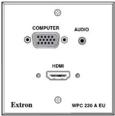
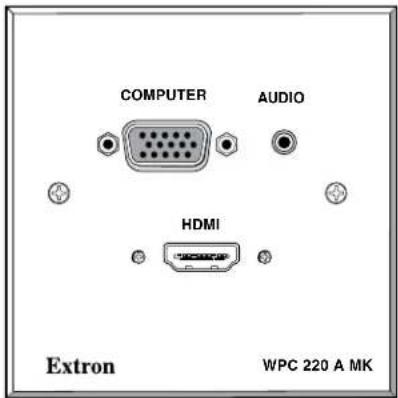
WPC 220 A EU WPC 220 A MK
VGA Wiring
NOTE: Extron recommends Extron MHRVGA bulk cable (part number 22-024-01) or assembled cables (part numbers 26-112-15, 26-112-36, 26-238-01, and 26-238-25). The wire colors for these products are shown in the VGA Connections table at the top of the next page. If other cable products are used, the colors may not correspond to those shown in the table.
The DDC and ID bit DIP switches, the +5 V pin, and the DDC pins are optional but they can affect the monitors supported by the system (see the table to the right of "DDC and ID Bit DIP Switch Settings" on the next page).
To connect wires from the VGA input to these modules, some wires must be cut shorter than others (see the table in the "VGA Connections" section on the next page). Follow these instructions:
- Run the unterminated end of the cable to the junction box.
- Strip away 3 inches (7.6 cm) from the end of the outer jacket of the cable.
- Unravel each of the coaxial shields and twist each, individually, to make 3 wires.
- Cut 1 inch (2.5 cm) from the end of the individual wires marked with an asterisk in the VGA Connections table on the next page.
- Strip 3/16 inches (5 mm) of the inner jacket from the end of each wire and secure the wire to the appropriate captive screw connector (see the VGA Connections and TRS Connections tables on the next page).
- Secure the faceplate to the junction box using the screws provided (see the figures at right).
- Connect the VGA input, audio input, or both.
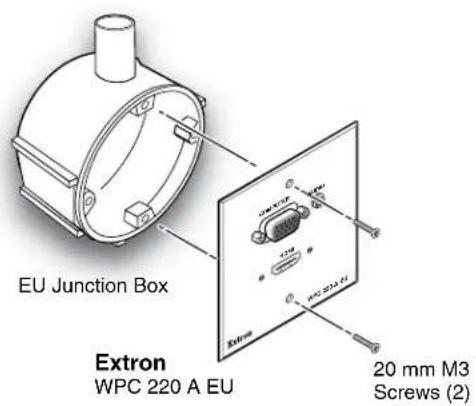
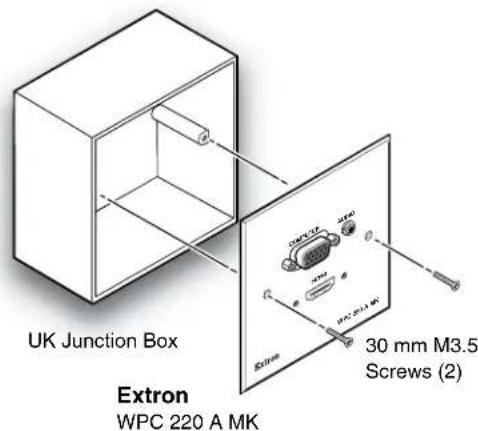
WPC 210 A Series • Installation Guide (Continued)
VGA and TRS Connections
| HD-15 Pin TRS Captive Screw Pin Color | |||
| 1 Red* R Red coax | |||
| 2 Green* G Green coax | |||
| 3 Blue* B Blue coax | |||
| 4 ID Bit 2 N/A Green (not used) | |||
| 5 Ground | 12 (right block) Violet | ||
| 6 Red Gnd* Rg Red coax shield | |||
| 7 Green Gnd* | Gg Green coax shield | ||
| 8 Blue Gnd* | Bg Blue coax shield | ||
| 9 DDC +5 V* (see note at right) | +5 | Gray | |
| 10 Sync Gnd* | 12 (main block) | Black (red/black pair) | |
| 11 ID Bit 0 | N/A Blue (not used) | ||
| 12 ID Bit 1 or DDC | D Yellow | ||
| 13 H sync* | H | Red (red/black pair) | |
| 14 V sync* | V | White (white/black pair) | |
| 15 ID Bit 3 or Clock C | Black (white /black pair) | ||
| * | Tip | Audio T (Left) | Orange |
| * | Ring | Audio R (Right) | Brown |
| * | Sleeve | Audio S (Ground) | Shield |
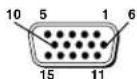
Female HD-15 Pin Locations
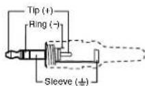
3.5 mm Stereo Plug Connector (balanced audio)
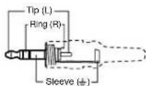
3.5 mm Stereo Plug Connector (unbalanced audio)
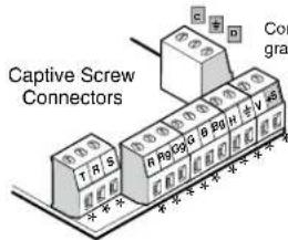
nectors labeled in are optional.
*Cut these wires 1 inch shorter. See the table at left.
NOTE: VGA pin 9 may be used to detect DDC availability. Check the manual for your display to see if this feature is required for DDC communication. If you are unsure, do not use the pin.
DDC and ID Bit DIP Switch Settings
The table at left below shows the function of the DIP switches. The table at right below shows how the switches affect the monitors supported and some of the more common ID bit settings. Check the manual supplied with your display to see if ID bit termination is required by your AV system. If you are unsure, set all switches to off.
NOTE: If DDC is to be used, switches 1 and 3 must be set to on and switches 2 and 4 must be set to off.
DIP Switches

| Switch | ID Bit Pin | Off | On | |
| 1 | ID 0 HD-1 | 5 pin 11 open | HD-1 | 5 pin 11 to ground |
| 2 | ID 1 HD-1 | 5 pin 12 pass-thru | HD-1 | 5 pin 12 to ground |
| 3 | ID 2 HD-1 | 5 pin 4 open | HD-1 | 5 pin 4 to ground |
| 4 | ID 3 HD-1 | 5 pin 15 pass-thru | HD-1 | 5 pin 15 to ground |
| Display Used | DIP Switch | |||
| 1 | 2 | 3 | 4 | |
| No ID bit required | Off | Off | Off | Off |
| Monochrome monitor (not XGA) | On | Off | Off | Off |
| Color monitor (not XGA) | Off | On | Off | Off |
| Color monitor (supports XGA) | Off | On | On | Off |
HDMI Connections
- Run a HDMI cable from the HDMI display to the junction box.
- Connect the cable to the rear panel HDMI connector. The rear panel HDMI connector is on a 6 inch (15.24 cm) pigtail, which provides extra flexibility to make the connection in the limited space of the junction box.
- Connect a HDMI source to the front panel HDMI connector.
| Extron Headquarters+1.800.633.9876 (Inside USA/Canada Only)Extron USA - West Extron USA - East+1.714.491.1500 +1.919.850.1000+1.714.491.1517 FAX +1.919.850.1001 FAX | Extron Europe+800.3987.6673(Inside Europe Only)+31.33.453.4040+31.33.453.4050 FAX | Extron Asia+65.6383.4400+65.6383.4864 FAX | Extron Japan+81.3.3511.7656+81.3.3511.7656 FAX | Extron China+86.21.3760.1568+86.21.3760.1566 FAX | Extron Middle East+971.4.299.1800+971.4.299.1880 FAX | Extron Korea+82.2.3444.1571+82.2.3444.1575 FAX | Extron India1800.3070.3777Inside India Only+91.80.3055.3777+91.80.3055.3737 FAX |
Brand : Extron
Model : WPC 220 A EU
Category : Wall socket