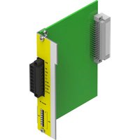
CAMC-G-S1 - Industrial electronic module Festo - Free user manual and instructions
Find the device manual for free CAMC-G-S1 Festo in PDF.


| Product Type | Servo Drive / Controller |
| Brand | Festo |
| Model | CAMC-G-S1 |
| Dimensions (approx.) | 200 x 150 x 80 mm |
| Weight (approx.) | 1.0 kg |
| Power Supply | 24 V DC |
| Main Functions | Position, velocity, and torque control; support for multiple communication protocols (CANopen, EtherCAT) |
| Communication Interfaces | CAN, EtherCAT, digital I/O |
| Control Mode | Closed-loop servo control |
| Operating Temperature | 0 °C to 55 °C |
| Protection Class | IP20 |
| Installation | Panel mount or DIN rail |
| Maintenance | Periodic inspection for dust and loose connections |
| Cleaning | Dry cloth, no solvents |
| Safety Features | Overcurrent protection, short-circuit protection, thermal shutdown |
| Safety Standards | CE, UL, RoHS |
| Spare Parts Availability | Available from Festo distributors |
| Reparability | Modular design; field-replaceable components |
| Warranty | Standard 24 months from Festo |
| General Information | Designed for industrial automation applications; supports various motor feedback types |
Frequently Asked Questions - CAMC-G-S1 Festo
User questions about CAMC-G-S1 Festo
0 question about this device. Answer the ones you know or ask your own.
Ask a new question about this device
Download the instructions for your Industrial electronic module in PDF format for free! Find your manual CAMC-G-S1 - Festo and take your electronic device back in hand. On this page are published all the documents necessary for the use of your device. CAMC-G-S1 by Festo.
USER MANUAL CAMC-G-S1 Festo
natural_image
Technical line drawing of an industrial control module with labeled ports (X40, Status) and internal components (no text or symbols beyond labels)FESTO
Manual | Safety function, STO

8179141
2022-07d
[8179143]
Translation of the original instructions
CANopen®, DEVICENET®, EtherCAT®, EtherNet/IP®, PI PROFIBUS PROFINET® are registered trademarks of the respective trademark owners in certain countries.
Table of contents
1 About this document.... 5
2 Safety and requirements for product use.... 8
2.1 Safety....8
2.1.1 General safety instructions....8
2.1.2 Intended use....8
2.1.3 Foreseeable misuse....8
2.1.4 Achievable safety level, safety function in accordance with EN ISO 13849-1/EN 61800-5-2....9
2.2 Requirements for product use....9
2.2.1 Technical prerequisites....9
2.2.2 Qualification of the specialist technicians (requirements for staff)....9
2.2.3 Diagnostic coverage (DC).... 10
2.2.4 Range of application and approvals.... 10
3 Product description of safety module CAMC-G-S1.... 11
3.1 Product overview.... 11
3.1.1 Purpose.... 11
3.1.2 Supported devices.... 11
3.1.3 Operating elements and connections.... 11
3.1.4 Scope of delivery.... 12
3.2 Function and application.... 12
3.2.1 Description of the STO safety function.... 12
3.2.2 Overview of interface [X40]. 14
3.2.3 Control inputs STO-A, 0V-A/STO-B, 0V-B [X40]. 15
3.2.4 Feedback contact C1, C2 [X40]. 16
3.2.5 24 V, 0 V auxiliary power supply [X40]. 16
3.2.6 Status indicator....16
3.2.7 DIL switch.... 16
3.3 Functions in the motor controller CMMP-AS-...-M3..... 16
3.4 Time response.... 18
3.4.1 STO basic time response.... 18
3.4.2 Time response of activation of STO in operation with restart.....19
3.4.3 Time response of activation of SS1 in operation with restart.....21
4 Assembly and installation.... 23
4.1 Mounting/removal....23
4.2 Electrical installation.... 24
4.2.1 Safety instructions.... 24
4.2.2 Connection [X40]. 24
4.2.3 Minimum wiring for initial start-up [X40]. 25
4.3 Sample circuits.... 26
4.3.1 Safe Torque Off (STO).... 26
4.3.2 Deceleration and Safe Torque Off (SS1, "Safe Stop 1"). 27
5 Commissioning....30
5.1 Prior to commissioning.... 30
5.2 DIL switch setting.... 30
5.3 Parameterisation with FCT.... 30
5.3.1 Setting the configuration.... 30
5.3.2 Apply module and status display of the module.... 31
5.3.3 Display permanent diagnostic memory of the motor controller....32
5.4 Function test, validation.... 34
6 Operation and use.... 37
6.1 Obligations of the operator.... 37
6.2 Maintenance and care....37
6.3 Protective functions....37
6.3.1 Voltage monitoring.... 37
6.3.2 Overvoltage and reverse polarity protection.... 37
6.4 Diagnostics and fault clearance.... 37
6.4.1 Status display.... 37
6.4.2 Error messages.... 38
7 Modification and module replacement.... 41
7.1 Replacement of the safety module.... 41
7.1.1 Repair....41
7.1.2 Disassembly and installation....41
7.2 Decommissioning and disposal.... 41
7.3 Replacement of the previous CMMP-AS series with the CMMP-AS-...-M3.....41
8 Technical appendix.... 43
8.1 Technical data.... 43
8.1.1 Safety engineering.... 43
8.1.2 General....44
8.1.3 Operating and environmental conditions.... 45
8.1.4 Electrical data.... 45
9 Glossary.... 48
1 About this document
Notes regarding this documentation
This documentation is intended to ensure that operators can work safely with the safety function STO – "Safe Torque Off" in accordance with EN 61800-5-2 by using the safety module CAMC-G-S1 for the motor controller CMMP-AS-...-M3.
- In addition, always observe the general safety regulations for the motor controller CMMP-AS-...-M3.
i
The general safety regulations for the CMMP-AS-...-M3 can be found in the hardware documentation, GDCP-CMMP-M3-HW-... → Tab. 6 Documentation for the motor controller CMMP-AS-...-M3.
Observe the information regarding safety and the requirements for product use in 2.2 Requirements for product use.
Product identification
i
This documentation refers to the following versions:
- Safety module CAMC-G-S1, from revision 03.
- Motor controller CMMP-AS-...-M3, firmware from version 4.0.1501.1.1.
• FCT plug-in CMMP-AS from version 2.3.x.
Rating plate (example) Meaning
CAMC-G-S11501330 XX #nnnnn  Rev XX Rev XX | Order reference CAMC-G-S1 |
| Part number 1501330 | |
| Production date XX | |
| Serial number #nnnnn | |
| Revision status Rev XX |
Tab. 1: Rating plate CAMC-G-S1
Service
Please consult your regional Festo contact if you have any technical problems.
Specified standards/directives
Version
| EN 61800-5-1:2007 + A1:2017 EN ISO 12100-1:2010 | |
| EN 61800-5-2:2007 EN ISO 13849-1:2015 | |
| EN 60204-1:2006 + A1:2009 + AC:2010 IEC 6113 | 1-2:2007 |
| EN 62061:2005 + AC:2010 + A1:2013 + A2:2015 | EC 61508-1/.../-7:2010 |
Tab. 2: Standards/directives specified in the document
Manufacturing period
The first 2 characters of the serial number on the rating plate indicate the manufacturing period in encrypted form Tab. 1 Rating plate CAMC-G-S1. The letter specifies the manufacturing year and the character after it (number or letter) indicates the manufacturing month.
Manufacturing year
| X = 2009 A = | 2010 B = 2011 | C = 2012 D = | 2013 E = 2014 | F = 2015 | ||
| H = 2016 J = | 2017 K = 2018 | L = 2019 M = | 2020 N = 2021 | P = 2022 | ||
| R = 2023 S = | 2024 T = 2025 | U = 2026 V = | 2027 W = 2028 | X = 2029 |
Tab. 3: Year of manufacture (20-year cycle)
Manufacturing month
| 1 January 2 February | |||
| 3 March 4 April | |||
| 5 May 6 June | |||
| 7 July 8 August | |||
| 9 September 0 October | |||
| N November D December |
Tab. 4: Manufacturing month
| CAMC | Electric plug-in cards |
| G | Safety module |
| S1 | Safe torque off |
Tab. 5: Type codes
Documentation
You will find additional information on the motor controller in the following documentation:
User documentation for the motor controller CMMP-AS-...-M3
| Name, type | Table of contents |
| Hardware manual,GDCP-CMMP-M3-HW-... | Assembly and installation of motor controller CMMP-AS-...-M3 for all variants/performance classes (1-phase, 3-phase), pin allocations, error messages, maintenance. |
| Functions manual,GDCP-CMMP-M3-FW-... | Functional description (firmware) CMMP-AS-...-M3, notes for commissioning. |
| User documentation for the motor controller CMMP-AS-...-M3 | |
| Name, type Table of contents | |
| FHPP manual,GDCP-CMMP-M3/-M0-C-HP-... | Control and parameterisation of the motor controller via the Festo FHPP profile.-Motor controller CMMP-AS-...-M3 with the following field-buses: CANopen, PROFINET, PROFIBUS, EtherNet/IP, DEVI-CENET, EtherCAT.- Motor controller CMMP-AS-...-M0 with fieldbus CANopen. |
| CiA 402 (DS 402) manual,GDCP-CMMP-M3/-M0-C-CO-... | Control and parameterisation of the motor controller via the device profile CiA 402 (DS 402)-Motor controller CMMP-AS-...-M3 with the following field-buses: CANopen and EtherCAT.- Motor controller CMMP-AS-...-M0 with fieldbus CANopen. |
| CAM Editor manual,P.BE-CMMP-CAM-SW-... | Cam disc functions (CAM) of the motor controller CMMP-AS-...-M3/-M0. |
| Safety module manual,GDCP-CAMC-G-S1-... | Functional safety engineering for the motor controller with the STO safety function. |
| Safety module manual,GDCP-CAMC-G-S3-... | Functional safety engineering for the motor controller with the STO, SS1, SS2, SOS, SBC, SLS, SSR, SSM safety functions. |
| Help for the FCT CMMP-AS plug-in User interface and functions of the CMMP-AS plug-in for the Festo Configuration Tool→ www.festo.com/sp. | |
Tab. 6: Documentation for the motor controller CMMP-AS-...-M3
2 Safety and requirements for product use
2.1 Safety
2.1.1 General safety instructions
- Also always observe the general safety regulations for the motor controller CMMP-AS-...-M3.
The general safety regulations for the CMMP-AS-...-M3 can be found in the hardware documentation, GDCP-CMMP-M3-HW-... Tab. 6 Documentation for the motor controller CMMP-AS-...-M3.
NOTICE
Failure of the safety function!
The safety functions might fail if you do not comply with the parameters required for the surroundings and connections.
- Observe the specified environmental and connection conditions, in particular the input voltage tolerances 8.1 Technical data.
NOTICE
Incorrect handling may damage the safety module or motor controller.
Incorrect handling may cause damage.
- Switch off the power supply before mounting and installation work. Do not switch on the supply voltages until mounting and installation work is completely finished.
- Never unplug or plug the module from/into the motor controller when powered!
- Observe the handling specifications for electrostatically sensitive devices.
2.1.2 Intended use
The safety module CAMC-G-S1 is an extension of the motor controller CMMP-AS-...-M3 for implementation of the safety function:
-Safe Torque Off (STO) with SIL 3 in accordance with EN 61800-5-2/EN 62061/IEC 61508 and/or category 4/PL e in accordance with EN ISO 13849-1.
The motor controller CMMP-AS-...-M3 with safety module CAMC-G-S1 is a product with safety-related functions and intended for installation in machines or automation systems and to be used as follows:
-in excellent technical condition,
- in its original condition, without unauthorised modifications,
- within the limits of the product defined by the technical data 8.1 Technical data,
-in an industrial environment.
The safety module CAMC-G-S1 can be operated in all motor controllers CMMP-AS-...-M3 that have the Ext3 slot for safety engineering. It cannot be plugged into one of the Ext1 or Ext2 slots for interfaces.
NOTICE
In the event of damage caused by unauthorised manipulation or use other than the intended use, the guarantee will be invalidated and the manufacturer will not be liable for damages.
2.1.3 Foreseeable misuse
The following are examples of foreseeable misuse and are not approved as intended use:
- use in a device other than the CMMP-AS-...-M3,
- use outdoors,
- use in non-industrial areas (residential areas),
- use in applications where switching off can result in hazardous movements or conditions.
NOTICE
- The STO function must not be used as the sole safety function for drives subject to permanent torque (e.g. suspended loads).
- Safety devices must not be bypassed.
• Repairs on the module are prohibited!
i
The STO (Safe Torque Off) function does not provide protection against electric shock, only against dangerous movements!
→ Hardware documentation, GDCP-CMMP-M3-HW-...
2.1.4 Achievable safety level, safety function in accordance with EN ISO 13849-1/EN 61800-5-2
The safety module fulfils the requirements for
-category 4/PL e in accordance with EN ISO 13849-1,
- SIL CL 3 in accordance with EN 62061,
and can be used in applications up to cat. 4/PL e in accordance with EN ISO 13849-1 and SIL 3 in accordance with EN 61800-5-2/EN 62061/IEC 61508.
The achievable safety level depends on the other components used to implement a safety function.
2.2 Requirements for product use
- Make this documentation available to the design engineer, installer and personnel responsible for commissioning the machine or system in which this product is used.
- Make sure that the specifications in the documentation are observed at all times. When so doing, also take into account the documentation for the other components and modules (e.g. motor controller, cables etc.).
-Take into account the legal regulations applicable for the location as well as:
-instructions and standards,
– regulations of testing organisations and insurers, - national specifications.
- If the safety function is required, protection against automatic restart in accordance with the required category must be installed. For example, an external safety relay unit can be used.
2.2.1 Technical prerequisites
General information on correct and safe use of the product, which must be observed at all times:
-Observe the connection and ambient conditions of the safety module ( 8.1 Technical data), the motor controller and all connected components as specified in the technical data.
Only compliance with the limit values and/or load limits will enable operation of the product in accordance with the relevant safety directives.
-Observe the notes and warnings in this documentation.
2.2.2 Qualification of the specialist technicians (requirements for staff)
The device may only be set into operation by a qualified electrical technician who is familiar with:
- the installation and operation of electrical control systems,
- the applicable instructions for operating safety engineering systems,
- the applicable instructions for accident prevention and occupational safety and
- the documentation for the product.
2.2.3 Diagnostic coverage (DC)
Diagnostic coverage depends on the integration of the motor controller with the safety module into the control loop system as well as the implemented diagnostics measures 6.4 Diagnostics and fault clearance.
If a potentially dangerous malfunction is recognised during diagnostics, appropriate measures must be taken to maintain the safety level.
NOTICE
Check whether detection of shorts across contacts of the input circuit and the connection wiring is required in your application.
If necessary, use a safety relay unit with detection of shorts across contacts to control the safety module.
2.2.4 Range of application and approvals
The motor controller with integrated safety module is a safety device. For details of the safety-oriented standards and test values that the product complies with and fulfils, see 8.1 Technical data.
The product-relevant directives are listed in the declaration of conformity → www.festo.com/sp.
Product conformity
| CE | in accordance with EU EMC Directivein accordance with EU Machinery Directivein accordance with EU RoHS Directive |
| UKCA | to UK EMC Regulationsto UK Supply of Machinery Regulationsto UK RoHS Regulations |
Tab. 7: Product conformity
3 Product description of safety module CAMC-G-S1
3.1 Product overview
3.1.1 Purpose
As processes become increasingly automated, protecting people from potentially hazardous movements is becoming ever more relevant. Functional safety refers to measures required of electrical or electronic equipment to reduce or eliminate dangers due to malfunctions. In normal operation, protective devices prevent human access to hazard zones. In certain operating modes, e.g. during set-up, people need to have access to danger zones. In such situations, the operator must be protected by measures incorporated into the drive and control system.
Integrated functional safety engineering provides the conditions required by controller and drive for the implementation of protective functions. Planning and installation complexity is reduced. The use of integrated functional safety engineering increases machine functionality and availability over the levels achieved by conventional safety engineering.
| Type Description | |
| CAMC-G-S1 Safety module with STO function and DIL switches. | |
| CAMC-G-S3 Safety module with the STO, SS1, SS2, SOS, SBC, SLS, SSR, SSM functions and DIL switches. | |
| CAMC-DS-M1 Switch module with DIL switches, no safety function. | |
Tab. 8: Overview of safety and switch modules for the CMMP-AS-...-M3
3.1.2 Supported devices
The safety module CAMC-G-S1 can be used in motor controllers exclusively in accordance with 2.1.2 Intended use. The motor controllers CMMP-AS-...-M3 are supplied without a module in slot Ext3. The safety functions of the integrated functional safety for safety-related stops described in this documentation can be expanded with the use of the safety module CAMC-G-S1.
i
If a safety function is not required, the switch module CAMC-DS-M1 must be ordered and installed in the Ext3 slot.
3.1.3 Operating elements and connections
The safety module CAMC-G-S1 has the following control components, connections and display components:
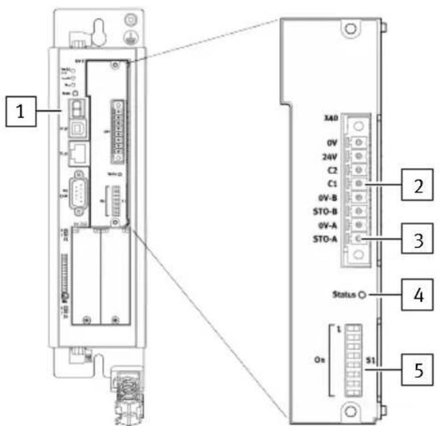
Fig. 1: Control section and connections CAMC-G-S1
1 Motor controller CMMP-AS-...-M3 with slot Ext3 for safety modules
2 Digital I/O interface [X40] for control of the STO function
3 Pin 1 of the interface [X40]
4 LED for display of the operating status (status of functional safety)
5 DIL switch (activation/configuration of fieldbus communication in the motor controller)
3.1.4 Scope of delivery
Safety module CAMC-G-S1
| Safety module with mounting accessories(2 screws with split washer) | Safe torque off module |
| Plug for control cables PHOENIX MiniCombicon MC | 1.5/8STF3.81 BK |
| Brief description with assembly instructions German | /English/Spanish/French/Italian/Chinese |
Tab. 9: Scope of delivery
3.2 Function and application
The safety module CAMC-G-S1 has the following performance characteristics:
- Reaching the "Safe Torque Off" (STO) function,
-Potential-free feedback contact for the operating status,
- Design as a module that can be plugged in from the outside thus enabling retrofits,
- Suitable exclusively for motor controllers of the series CMMP-AS-...-M3.
The “Safe Stop 1” (SS1) function can be implemented with a suitable external safety relay unit and appropriate circuitry for the motor controller CMMS-AS-...-M3.
3.2.1 Description of the STO safety function
Use the "Safe Torque Off" function (STO) whenever you need to disconnect the energy supply to the motor reliably in your application.
The “Safe Torque Off” function switches off the driver power supply for the power semiconductor, thus preventing the power output stage from supplying the power required by the motor; see the diagram below.

Fig. 2: "Safe torque off" - functional principle for the CMMP-AS-...-M3
1 Safety circuit (switch, relay, safety relay unit)
5 Motor connection
2 Safety module CAMC-G-S1
6 LED (green/yellow), status indicator
3 Power output stage in the CMMP-AS-...-M3 (only one phase shown)
7 Feedback contact
4 Driver power supply
The power supply to the drive is safely disconnected when the STO “Safe Torque Off” safety function is active. The drive cannot generate torque and so cannot perform any dangerous movements. With suspended loads or other external forces, additional measures must be taken to ensure that the load does not drop (e.g. mechanical holding brakes). The standstill position is not monitored in the STO “Safe Torque Off” state.
The machine must be brought to a standstill in a safe manner and secured, e.g. with a safety relay unit. This especially applies to vertical axes without automatic locking mechanisms, clamping units or counterbalancing.
NOTICE
There is a danger that the drive will advance if there are multiple errors in the CMMP-AS-...-M3. If the power stage of the motor controller fails during the STO state (simultaneous short circuit of 2 power semiconductors in different phases), this can result in a limited detent movement of the rotor. The rotation angle/travel corresponds to one pole pitch. Examples:
- rotary axis, synchronous machine, 8-pole movement < 45^ at the motor shaft.
- linear motor, pole pitch 20 ~mm movement < 20 ~mm at the moving part.
3.2.2 Overview of interface [X40]
The safety module has an 8-pin connection [X40] on the front for control inputs, feedback contact and a 24 V auxiliary supply for external sensors → 4.2 Electrical installation.
The STO safety function is requested exclusively via the two digital control inputs STO-A and STO-B. Safety circuitry for additional interfaces on the CMMD-AS-...-M3 motor controller is neither required nor intended.
i
The safety module does not detect shorts across contacts of the input circuit.
The status of the motor controller is sent to an external safety relay unit via a potential-free feedback contact (N/O contact). This means that a downward compatible interface can be implemented in a mixed configuration consisting of CMMP-AS (previous series with the “safe stop” function via the [X3] connection) and the CMMP-AS-...-M3 → 7.3 Replacement of the previous CMMP-AS series with the CMMP-AS-...-M3. The interface [X40] allows direct connection of active and passive sensors, because a 24 V supply voltage (auxiliary supply) with associated reference potential is connected.
Ports Description
| STO-A (Pin 1)0V-A (Pin 2) | Control input A for the STO function with the associated reference potential- "Safe Torque Off" (STO) request at low (logic 0), together with STO_B.Control input 24 V, high active, based on EN 61131-2, signal level deviating from→8.1.4 Electrical data,→Tab. 31 Technical data: electrical data of the STO-A and STO-B inputs. |
| STO-B (Pin 3)0V-B (Pin 4) | Control input B for the STO function with the associated reference potential.- "Safe Torque Off" (STO) request at low (logic 0), together with STO_A.Control input 24 V, high active, based on EN 61131-2, signal level deviating→8.1.4 Electrical data,→Tab. 31 Technical data: electrical data of the STO-A and STO-B inputs. |
| C1) (Pin 5)C2) (Pin 6) | Feedback contact for the "Safe Torque Off" status (STO), e.g. to an external controller. |
| - Feedback contact open: "Safe Torque Off" (STO) not active | |
| - Feedback contact closed: "Safe Torque Off" (STO) active | |
| 24V (Pin 7)0V (Pin 8) | Auxiliary power supply, e.g. for safety-oriented peripherals (24 V DC logic power supply of the motor controller). |
Tab. 10: Function of the connections of the module [X40]
The connections are galvanically isolated in groups from one another and from the 24 V power supply of the motor controller 8.1.4 Electrical data, Tab. 34 Technical data: electrical data of the auxiliary supply output.
3.2.3 Control inputs STO-A, 0V-A/STO-B, 0V-B [X40]
The STO (Safe Torque Off) safety function is requested via two channels with the two control inputs STO-A and STO-B. They allow the direct connection of safe semiconductor outputs (electronic safety relay units, active safety sensors, e.g. light curtains with OSSD signals) and switching contacts (safety relay units with relay outputs, passive safety sensors, e.g. positively driven position switches) Fig. 7.
In order to request the STO (Safe Torque Off) safety function, the 24 V control voltage is switched off at both control inputs STO-A and STO-B (0 V).
If the two control ports are switched off simultaneously or within a defined discrepancy time, the STO safety function is active.
Undervoltage monitoring is integrated for the STO-A and STO-B control inputs in order to rule out invalid voltage ranges for the downstream electronics, as well as overvoltage monitoring to protect against overvoltage.
i
Technical data for the control inputs in the specified operating range of logic voltages 8.1.4 Electrical data,→ Tab. 31 Technical data: electrical data of the STO-A and STO-B inputs.
Tolerance ranges are defined for the input voltage range of the STO-A and STO-B control inputs. The amount of energy stored in the components of the safety module (e.g. capacitors) depends on the magnitude of the input voltage. This amount of energy must be charged or discharged during switching operations. The input voltage-dependent values are thus derived for the switch-off time for the transition to the safe state (STO) and the tolerance time for OSSD signals (buffer time).
The requirements for the time response are derived from the technical data 8.1.4 Electrical data. The time response itself is described here 3.4 Time response.
Discrepancy time
The transition between a safe and an unsafe state is initiated by level changes at the STO-A and STO-B control inputs of the safety module CAMC-G-S1. According to the specification of the safety function, both levels must be identical, otherwise an error message is generated. The state machine in the motor controller internally monitors the driver supply voltages as a result of the control of the control inputs. The level changes do not usually take place exactly simultaneously, for example, because of component tolerances or bouncing outputs of safety controls. The firmware tolerates this as long as the second input follows within a defined time, the so-called discrepancy time. If the time is exceeded, the motor controller generates an error message.
A discrepancy time of 100 ms is the default.
Recommendation: always switch STO-A and STO-B simultaneously.
Test pulses
Temporary test pulses from safety controllers are tolerated and thus do not lead to the request of the STO function.
The tolerance to test pulses from sensors with OSSD signals is designed for the operating range according to 8.1.4 Electrical data, Tab. 32 Typical switch-off time and minimum tolerance time for test pulses (OSSD signals). The permissible test pulse length depends on the control voltage level at the STO-A and STO-B inputs.
Example: input voltage for STO-A and STO-B = 24 V → OSSD signals with a test pulse length of 3.5 ms are tolerated.
3.2.4 Feedback contact C1, C2 [X40]
If the STO function is not active, the feedback contact is opened. For example, this is the case if only one of the two STO-A or STO-B control voltages is present, if the 24 V logic supply voltage is switched off or the supply voltage fails.
When the STO function is active, the relay contact is closed.
i
The feedback contact is single-channel and may be used for diagnostic purposes, but not in the safety circuit.
Electrical data of the feedback contact 8.1.4 Electrical data, Tab. 33 Technical data: electrical data of the feedback contact C1/C2. Time response of the feedback contact Tab. 32 Typical switch-off time and minimum tolerance time for test pulses (OSSD signals).
When the 24 V supply of the basic unit is switched on and off, the switching status of the relay may deviate briefly (approx. 100 ms) from the status of the STO-A and STO-B control inputs due to the difference in speed at which the internal supply voltage starts up.
3.2.5 24 V, 0 V auxiliary power supply [X40]
The motor controller CMMP-AS...-M3 with the safety module CAMC-G-S1 provides a 24 V auxiliary supply at [X40]. This can be employed when using the C1/C2 feedback contact or for power to external active sensors.
i
Electrical data of the auxiliary power supply 8.1.4 Electrical data, Tab. 34 Technical data: electrical data of the auxiliary supply output.
3.2.6 Status indicator
The safety module has an LED on the front to indicate the status of the safety function 6.4.1 Status display.
The status LED shows the operating status of the module (green = STO not active, yellow = STO active). The display corresponds to the status of the C1/C2 feedback contact.
3.2.7 DIL switch
DIL switches are located on the front panel of the safety module. They do not have a safety function. The meaning of the individual switches depends on the interface used for fieldbus communication. The DIL switches can be used to activate/deactivate fieldbus communication and, for example, to set up a device address.
3.3 Functions in the motor controller CMMP-AS-...-M3
The following functions in the motor controller CMMP-AS-...-M3 are not certified according to EN 61800-5-2. They are functional supplements and offer additional diagnostic options.
Error messages generated by the safety module, e.g. exceeding the discrepancy time, are recorded and evaluated by the non-safety-related state machine of the motor controller. If the conditions for an error status are detected, an error message is generated. In this case, it cannot be guaranteed under all circumstances that the power output stage has been safely switched off.
The safety module CAMC-G-S1 exclusively controls the provision of the driver power supply for the motor controller CMMP-AS-...-M3. Although the levels of the input voltage are monitored section by section, the safety module does not have its own error evaluation mechanisms and also does not have the option of displaying an error.
NOTICE
When error messages are acknowledged, all acknowledgeable errors regarding functional safety are also acknowledged 6.4.2 Error messages.
The motor controller CMMP-AS-M3 monitors the status of the STO-A and STO-B control inputs. As a result, the request for the STO (Safe Torque Off) safety function is detected by the firmware of the motor controller and various non-safety-related functions are then executed:
- detection of the shutdown of the driver power supply for the power semiconductors by the safety module,
- switching off the drive control and the control of the power semiconductors (PWM),
- the holding brake control is switched off (if configured),
-state machine on the motor controller side with evaluation of the control (discrepancy time),
-detection of application-related error states, - hardware diagnostics,
-status and error indication via display, digital outputs, fieldbuses etc.
NOTICE
A brake is actuated by the non-safety-relevant firmware of the motor controller.
NOTICE
If one of the STO-A or STO-B control inputs is deactivated while the power stage is active, this will result in the drive coasting down without braking if the holding brake is not connected.
This may damage the machine. We therefore recommend connecting a holding brake to the motor controller.
i
Please check whether the motors you are using with a holding brake are designed to brake and stop the motor with the holding brake in the event of a fault.
A safe state with active control of the power semiconductors (PWM) can be requested. The status of both driver supply voltages is recorded and evaluated in a 10 ms cycle. If they are unequal over a longer period of time, an error message is triggered → 6.4.2 Error messages. The safety function assumes that both signals have the same status. Unequal signals are only tolerated during a transition period, the so-called "discrepancy time" → 3.2.3 Control inputs STO-A, 0V-A/STO-B, 0V-B [X40].
This state machine in the motor controller CMMP-AS-...-M3 has its own status parallel to the safety module CAMC-G-S1. Due to the assessment of the discrepancy time, this state machine may only reach the "safe state" with a significant delay. Accordingly, this state can only be signaled with a significant delay via digital outputs or a fieldbus. The power output stage itself is then already "safely switched off". This status machine is processed in a 10 ms cycle.
This results in a staggered reaction speed according to the following table:
| Function Reaction time Reaction | ||
| Switching time from high to low | T_STO-A/B_OFF | →8.1.4 Electrical data, →Tab. 31 Technical data: electrical data of the STO-A and STO-B inputs |
| Switching time from low to high | T_STO-A/B_ON | |
| Detection of failure Driver power supply | tReaction≤125 μs Control of the power semiconductors (PWM) is switched off | |
| Activate holding brake t | Reaction≤10 ms Actuation of the holding brake after detecting the failure of the driver power supply | |
| Signal evaluation and status indicator | tReaction≤10 ms Status transitions in the internal status machine, triggering of an error message if necessary and showing the status on the display | |
Tab. 11: Driver supply voltage acquisition and reaction times
3.4 Time response
i
The STO-A and STO-B inputs are functionally absolutely equivalent, therefore, the switching sequence of STO-A/STO-B is interchangeable in all diagrams.
3.4.1 STO basic time response
The figure below shows the basic time response of the safety module. The times can be found in the table below.

other
| Channel | State | State Description | |-----------------|----------------|----------------------------------------| | CAMC-G-S1 | STO-A | Open (Sto - Safe Torque Off) | | CAMC-G-S1 | STO-B | Open (Sto - Safe Torque Off) | | CAMC-G-S1 | Status LED | Open (Sto - Safe Torque Off) | | CAMC-G-S1 | Status C1/C2 | Closed (T_STO-A/B_OFF) | | CMMP-AS-...M3 | Display | Dependent on the operating status | | CMMP-AS-...M3 | Display | "H" – STO reached | | CMMP-AS-...M3 | Display | Dependent on the operating status | | CMMP-AS-...M3 | Safety status* (internal) | "Standard" → "Standard" | | CMMP-AS-...M3 | Safety status* (internal) | "H" – STO reached | | CMMP-AS-...M3 | Safety status* (internal) | Dependent on the operating status | | CMMP-AS-...M3 | Safety status* (internal) | T_DRIVE_V → T_DRIVE_V | | CMMP-AS-...M3 | Safety status* (internal) | T_DRIVE_V → T_DRIVE_V | | CMMP-AS-...M3 | Safety status* (internal) || Time Description Value | ||
| T_STO-A/B_OFF STO-A/B – switching time from high to low | →8.1.4 Electrical data,→Tab. 31 Technical data:electrical data of the STO-A and STO-B inputs | |
| T_STO-A/B_ON STO-A/B – switching time from low to high | ||
| T_C1/C2_ON C1/2 – switching time for closing | →8.1.4 Electrical data,→Tab. 33 Technical data:electrical data of the feed-back contact C1/C2 | |
| T_C1/C2_OFF C1/2 – switching time for opening | ||
| T_DRIVE_V Delay of the CMMP-AS-M3 0 ... 10 ms | ||
3.4.2 Time response of activation of STO in operation with restart
The figure below shows the time response from switching off the control voltage at STO-A/B and the process required to restart the device. The times can be found in the table below. Notes: - The holding brake is controlled via the motor controller, not safety-related. - The coasting of the motor is shown, independent of activation/deactivation of the brake. - The setpoint value is only enabled when the holding brake delay T\_BRAKE\_V has expired. line
| Panel | Event Description | Timeframe Labels | |-------|-------------------|------------------| | CAMC-G-S1 | STO-A / STO-B | - | | CAMC-G-S1 | Status LED (~ C1/C2) | - | | CMMP-AS-...M3 | Controller enable DIN5 | - | | CMMP-AS-...M3 | Speed | - | | CMMP-AS-...M3 | Holding brake (optional) | - | | CMMP-AS-...M3 | "Output stage enable" (internal) | - || Time Description Value | ||
| T_STO-A/B_OFF STO-A/B – switching time from high to low | →8.1.4 Electrical data,→Tab. 31 Technical data: electrical data of the STO-A and STO-B inputs | |
| T_STO-A/B_ON STO-A/B – switching time from low to high | ||
| T_DIN5_LOW Time that DIN5 must be low before STO-A/B is switched on again | 0 ms | |
| T_DIN5_SU Time that DIN5 must still be low after switching on STO-A/B again and changing the status of the STO module | >20 ms | |
| T_DRIVE_V Delay of the CMMP-AS-M3 0 ... 10 ms | ||
| T_BRAKE_V_ON Switch-off delay of the holding brake Depending on the brake | 1) | |
| T_BRAKE_V_OFF Switch-on delay of the holding brake Depending on the brake | 2) | |
3.4.3 Time response of activation of SS1 in operation with restart
The time response in the following figure is based on the example circuit for SS1 in 4.3.2 Deceleration and Safe Torque Off (SS1, "Safe Stop 1"), based on the control signal S1 for K1. The times can be found in the table below. Safety switching device other
| Signal | State | Condition | Value | |--------|-------|-----------|-------| | S1 | Closed | Open | 1 | | K1 | Closed | Open | T_K1 | | K1 | Closed | Open | T_K1_V | | CAMC-G-S1 | Status LED (~ C1/C2) | on/off | on | | CAMC-G-S1 | Status LED (~ C1/C2) | OFF | T_STO-A/B_OFF | | CAMC-G-S1 | Status LED (~ C1/C2) | ON | T_STO-A/B_ON | | CMMP-AS-...-M3 | Controller enable DIN5 | Speed | T_DRIVE_V | | CMMP-AS-...-M3 | Controller enable DIN5 | Power | 0 | | CMMP-AS-...-M3 | Controller enable DIN5 | Power | T_DRIVE_V | | CMMP-AS-...-M3 | Controller enable DIN5 | Power | T_DIN5_SU | | Holding brake (optional) | 24 V | Power | 0 | | Holding brake (optional) | 24 V | Power | T_DRIVE_V | | Holding brake (optional) | 24 V | Power | T_DRIVE_V | | Holding brake (optional) | 24 V | Power | T_BRAKE_V_ON | | Holding brake (optional) | 24 V | Power | T_BRAKE_V_OFF | | Output stage enable" (internal) | 0 V | Power | 0 | | Output stage enable" (internal) | 0 V | Power | T_BRAKE_V_ON | | Output stage enable" (internal) | 0 V | Power | T_BRAKE_V_OFF | | Custom Control (STO-A/STO-B) | Closed | Open | T_K1 | | Custom Control (STO-A/STO-B) | Closed | Open | T_K1_V | | Custom Control (STO-A/STO-B) | Closed | Open | T_STO-A/B_ON | | Custom Control (STO-A/STO-B) | Closed | Open | T_DIN5_SU | | Custom Control (STO-A/STO-B) | Closed | Open | T_BRAKE_V_ON | | Custom Control (STO-A/STO-B) | Closed | Open | T_BRAKE_V_OFF | The chart includes labels for each step: "Status LED (~ C1/C2)" and "Control enable DIN5". The time intervals are marked with arrows.| Time Description Value | ||
| T_K1 Delay time between switching S1 and closing instantaneous contact K1 | → Data sheet of the safety relay unit | |
| T_K1_V Delay time between S1 and opening of the off-delayed contacts K1 | Adjustable on the safety relay unit | |
| T_STO-A/B_OFF STO-A/B – switching time from high to low | → 8.1.4 Electrical data,→ Tab. 31 Technical data: electrical data of the STO-A and STO-B inputs | |
| T_STO-A/B_ON STO-A/B – switching time from low to high | ||
| T_DRIVE_V Delay of the CMMP-AS-M3 0 ... 10 ms | ||
| Time Description Value | ||
| T_DIN5_SU Time that | at DIN5 must still be low after switching on STO-A/B again and changing the status of the STO module | |
| T_BRAKE_V_ON Switch-off delay of the holding brake Depending on the brake | ||
| T_BRAKE_V_OFF Switch-on delay of the holding brake Depending on the brake | ||
4 Assembly and installation
4.1 Mounting/removal
The safety module CAMC-G-S1 is suitable exclusively for integration into the motor controller CMMP-AS-...-M3. It cannot be operated outside the motor controller. The motor controller must be disconnected from any live cables before installing and removing the safety module. WARNING
Danger of electric shock if the safety module is not mounted.
Touching live parts causes severe injuries and may cause death. Before touching live parts during maintenance, repair and cleaning work and when there have been long service interruptions: 1. Switch off power to the electrical equipment at the main switch and lock the switch to prevent reactivation. 2. After switch-off, wait at least 5 minutes discharge time and check that there is no power before accessing the controller.NOTICE
Incorrect handling may damage the safety module or motor controller.
\- Switch off the power supply before mounting and installation work. Do not switch on the supply voltages until mounting and installation work is completely finished. \- Never unplug a module from, or plug a module into, the motor controller when powered! \- Observe the handling specifications for electrostatically sensitive devices. Do not touch the components and conductive tracks on the PCB or the pins on the terminal strip in the motor controller. Hold the safety module only by the front plate or the edge of the PCB. Mounting the safety module natural_image
Technical line drawing of an electronic device showing internal components and a separate terminal block (no text or symbols present)Removing the safety module
1. Unscrew screws. 2. Release the safety module a few millimetres by gently levering the front panel or by pulling on the mating plug and pull it out of the slot.4.2 Electrical installation
4.2.1 Safety instructions
The requirements of EN 60204-1 must be fulfilled in the installation. WARNING
Danger of electric shock from voltage sources without protective measures.
- Only use PELV circuits in accordance with EN 60204-1 (protective extra-low voltage, PELV) for the electrical logic power supply. Also, take into account the general requirements for PELV circuits in accordance with EN 60204-1. - Only use power sources that guarantee reliable electrical isolation of the operating voltage from the mains in accordance with EN 60204-1. Protection from electric shock (protection from direct and indirect contact) in accordance with EN 60204-1 (Electrical equipment of machines, General requirements) is guaranteed with the use of PELV circuits. The 24 V fixed power supply used in the system must meet the requirements of EN 60204-1 for DC power supplies (response in the event of voltage interruptions etc.). The cable is connected to a plug, which makes it easier to replace the safety module. i Make sure that no jumpers or the like can be inserted parallel to the safety wiring, e.g. by the use of the maximum wire cross section of 1.5 mm^2 or suitable wire end sleeves with insulating collars. Use twin wire end sleeves for looping cables between adjacent devices.ESD protection
Damage may be caused to the device or to other system parts at unassigned plugs as a result of ESD (electrostatic discharge). Earth the system parts prior to installation and use appropriate ESD equipment (e.g. shoes, earthing straps etc.).4.2.2 Connection [X40]
The safety module CAMC-G-S1 has a combined interface for control and feedback via the plug connector [X40]. - Version on the device: PHOENIX MINICOMBICON MC 1.5/8-GF-3.81 BK -Plug (in scope of delivery): PHOENIX MINICOMBICON MC 1.5/8-STF-3.81 BK, connection corresponding to → 8.1.4 Electrical data, → Tab. 36 Technical data: wiring at [X40]. Plugs Pin Designation Value Description| 8 | ![Festo CAMC-G-S1 - Connection [X40] - 1](/content/2026/05/999060/images/2d38316040c21dc253dc3d1715e25d1b9b6aeb837987281f24493591a48deadb.jpg) | 8 0V 0 V Reference potential for auxiliary power supply. | ||
| 7 24V +24 V DC Auxiliary supply voltage (from the 24 V DC logic supply of the motor controller). | ||||
| 1 | 6 C2) - Feedback contact for the “STO” status on an external controller. | |||
| 5 C1) | ||||
| 4 0V-B 0 V Reference potential for STO-B. | ||||
| 3 STO-B 0 V / 24 V Control input B for the STO function. | ||||
| 2 0V-A 0 V Reference potential for STO-A. | ||||
| 1 STO-A 0 V / 24 V Control input A for the STO function. | ||||
4.2.3 Minimum wiring for initial start-up [X40]
If a safety-related interface is not (yet) present, the switch module CAMC-DS-M1 should be used. i You must configure and acknowledge the module replacement in the FCT→5.3 Parameterisation with FCT. If necessary, also note the setting of the DIL switch 5.2 DIL switch setting. If a switch module is not available or the motor controller is to be initially commissioned without safety engineering, the motor controller CMMP-AS-...-M3 can be wired to the safety module CAMC-G-S1 with minimum circuitry with an emergency stop switch Fig. 7, [2].NOTICE
Safety functions must never be bypassed. Install the minimum circuits for the STO-A/STO-B and 0V-A/0V-B inputs for initial commissioning in such a way that they must be removed when the final safety circuitry is installed.4.3 Sample circuits
4.3.1 Safe Torque Off (STO)
 Fig. 7: Connection of the safety module CAMC-G-S1 using the example of a single-phase motor controller CMMP-AS-...-3A-M3 1 Motor controller with safety module (only relevant connections shown) 4 Light curtain 2 Emergency stop switch 5 Safety relay unit 3 Safety door The "Safe Torque Off" (STO) safety function can be requested by various devices. For example, the S1 switch may be an emergency stop switch, a safety door switch, a light curtain or a safety relay unit. The security requirement is made in 2 channels via the S1 switch and leads to the 2-channel switch-off of the power stage. If the power stage has been switched off, it is output by the potential-free contact C1/C2.Information on the sample circuit:
- Detection of shorts across contact is not integrated in the motor controller with safety module. The direct wiring of light curtains means that detection of shorts across contacts is implemented by the light curtain, if it is designed for this purpose. - When using safety relay units, contact C1, C2 can be integrated into the feedback circuit of the safety relay unit.Assembly and installation
- The sample circuit has a 2-channel structure that is suitable for categories 3 and 4 with additional measures. - The additional measures required depends on the area of application and the safety concept of the machine.4.3.2 Deceleration and Safe Torque Off (SS1, "Safe Stop 1")
The "Safe Stop 1" (SS1, Type C) safety function can be requested by various devices, see the following figure. For example, the S1 switch in the following figure may be an emergency stop switch, a safety door switch or a light curtain. The security requirement is made in 2 channels via the S1 switch and to the safety relay unit. The safety relay unit switches off the controller release. If the controller release of the motor controller is switched off, the movement is automatically delayed, the activation of the brake is delayed if the brake is configured and the control loop is then switched off. After a time set in the safety relay unit, the output stage is switched off via 2 channels via STO-A/B. If the power stage has been switched off, it is output by the potential-free contact C1-C2. flowchart
graph TD
    A["1"] --> B["S1"]
    B --> C["or"]
    C --> D["S1"]
    D --> E["2"]
    E --> F["or"]
    F --> G["S1"]
    G --> H["Sender"]
    G --> I["Receiver"]
    H --> J["05501"]
    I --> K["05502"]
    J --> L["STO-A"]
    J --> M["STO-B"]
    K --> N["0V-A"]
    K --> O["0V-B"]
    K --> P["C1"]
    K --> Q["C2"]
    L --> R["DIN5"]
    L --> S["DIN4"]
    M --> T["X40"]
    N --> U["-X1"]
    O --> V["-X9"]
    P --> W["-X1"]
    Q --> X["-X1"]
    R --> Y["L1"]
    S --> Z["N"]
    T --> AA["PE"]
    U --> AB["+24 V"]
    V --> AC["GND 24 V"]
    W --> AD["Output stage enable"]
    X --> AE["Output PLC: Output control enable"]
    Y --> AF["L230 V AG"]
    Z --> AG["N 230 V AG"]
    AA --> AH["PE"]
    AB --> AI["24 V DC"]
    AC --> AJ["0 V DC"]
    AD --> AK["Safety switch device"]
    AE --> AL["Feedback circuit"]
    AF --> AM["Safety feedback"]
    AG --> AN["Safety feedback"]
    AH --> AO["Safety feedback"]
Information on the sample circuit:
- The safety relay unit used must switch off the controller enabler (X1-9, DIN5) without time delay and the inputs STO-A and STO-B (X40-1, -3) with time delay. - The required time delay depends on the application and must be determined specific to the application. The time delay must be designed in such a way that the drive is braked to zero even at the highest speed via the quick stop ramp in CMMP-AS...-M3 before STO-A/B are switched off.Assembly and installation
- The electrical installation has been carried out in accordance with the requirements of EN 60204-1. For example, the safety relay unit and the motor controller are located in the same control cabinet to enable fault exclusion for a cross or earth fault between the cables (acceptance test of the control cabinet for fault-free wiring). - The sample circuit has a 2-channel structure that is suitable for categories 3 and 4 with additional measures. - The additional measures required depends on the area of application and the safety concept of the machine.5 Commissioning
NOTICE
Failure of the safety function!
Absence of the safety function can result in serious, irreversible injuries, e.g. due to unintentional movements of the connected actuator technology. - Operate the safety module only: - if it is installed and - if all protective measures have been initiated. - Validate the safety function to complete commissioning 5.4 Function test, validation. i Incorrect wiring, use of an incorrect safety module or external components that were not selected corresponding to the category will result in failure of the safety function. - Carry out a risk assessment for your application and select the circuitry and components accordingly. - Observe the examples 4.3 Sample circuits.5.1 Prior to commissioning
Carry out the following steps in preparation for commissioning: 1. Make sure that the safety module is correctly mounted 4.1 Mounting/removal. 2. Check the electrical installation (connecting cables, contact assignment 4.2 Electrical installation). All PE conductors connected?5.2 DIL switch setting
The safety module has DIL switches for activation and control of the fieldbus configuration. The functionality of the DIL switches is identical to that of the switch module CAMC-DS-M1 and depends on the fieldbus interface used. i Set the DIL switches as described in the hardware documentation GDCP-CMMP-AS-M3-HW-... or the corresponding documentation for the fieldbus 1 About this document, Tab. 6 Documentation for the motor controller CMMP-AS-...-M3.5.3 Parameterisation with FCT
5.3.1 Setting the configuration
Functional safety requires that engineering changes can be traced. To guarantee this, the specifications for module type, serial number, version and revision are stored in the safety module. This data is stored in the motor controller as comparison values. This makes it possible to detect an engineering change in the components. For the safety module project engineering, insert the safety module into the FCT on the 'Configuration' screen of the CMMP-AS plug-in with 'Create new drive configuration' or 'Change drive configuration', see the following figure.  Fig. 9: FCT plug-in CMMP-AS: create/edit drive configuration As soon as you create an online connection to the motor controller, you receive module type, serial number, version and revision of the module→5.3.2 Apply module and status display of the module.5.3.2 Apply module and status display of the module
If an engineering change is detected, e.g. a module replacement, a non-acknowledgeable error is triggered. To be able to restart the application with the motor controller, the change must be “projected”. This means that the change is explicitly accepted or confirmed. With reference to the safety or switch modules, these traceable changes involve a module replacement.i
The following rules apply to the module replacement: \- It is always possible to replace a switch module with another switch module. - It is not necessary to confirm the replacement of a CAMC-G-S1 module with another CAMC-G-S1 module. Exception: the version check in the basic unit shows that the modules are incompatible - error message 51-3 - meaning that the module change must be confirmed. \- When a module type is replaced with a different type – error message 51-2 – the module replacement must always be confirmed. \- When a CAMC-G-S3 module is replaced with a CAMC-G-S3 – error message 51-6 – the module replacement must also always be confirmed. You have two options for confirming the module replacement:Commissioning
- When activating online mode, the module change is detected and a confirmation dialogue is automatically displayed. - If you have not confirmed the module change directly when activating online mode, you can open the confirmation dialogue at any time using the menu command ‘Component’ ‘Online’ ‘Confirm module change’. The ‘Confirm module change’ dialogue displays the module type, overall revision (CAMC-G-S3) or revision and version (CAMC-G-S1, CAMC-DS-M1) and the serial numbers of the previous module and also of the currently installed module. -Selecting 'Yes' confirms the module replacement, the parameters are permanently saved in the basic unit and the system is restarted.Status indicator
Information on the status of the safety module is displayed in the project output section of the ‘Safety functions’ tab in online mode.| Characteristics Display Status | ||
| Status:Display of the module status | Green Normal operation (STO not requested) | |
| Yellow STO requested and achieved | ||
| Red Safety circuit error | ||
| Input X40.STO-A:Display of the input status | Grey Safety function requested, STO-A = Low | |
| Green Safety function not requested, STO-A = High | ||
| Input X40.STO-B:Display of the input status | Grey Safety function requested, STO-B = Low | |
| Green Safety function not requested, STO-B = High | ||
| Output X40.C1/C2:Display of the relay contact | Orange Safety function active, relay contact closed | |
| Grey Safety function inactive, relay contact open | ||
5.3.3 Display permanent diagnostic memory of the motor controller
To display or save the permanent diagnostic memory, activate the online ‘Diagnostics’ tab in the FCT plug-in. If there is an active online connection, you should activate the ‘Permanent’ tab. ‘Read’ reads the number of entries of the permanent diagnostic memory specified under ‘Entries’ and displays them in chronological order, newest first. Selecting ‘All entries’ reads the complete permanent diagnostic memory. This can take a few minutes. The content of the diagnostic memory is displayed in the form of a table:| Column Explanation | |
| No. Sequence number of the entry. | |
| Fault no. Error, warning or event number → 6.4.2 Error messages. | |
| Fault description Name of the entry, error text. | |
| Time stamp Time of the diagnostic event in<hh>:<mm>:<ss> format (operating hour counter, duty cycle of the logic supply). | |
| Constant Additional information for Festo service personnel | |
| Free parameter Additional information for Festo service personnel | |
| Type Type of entry (error, warning, log entry). | |
| No. | Fault no. | Fault description Time | stamp Con- | stant | Free parameter Type | |
| 1 00 | -21 Log e | entry of the safety module | 580:15:03 | 0x0000 | Error acknowledged, source: 0x01, error-free | Errors |
| 2 | 00-8 | Controller switched on | 580:15:00 | 0x0000 | 0x0000 | Errors |
| 3 00 | -11 Modu | le change: current module | 580:15:22 | 0x48FF C | AMC-DS-M1, S/N: 3781764777, HW rev.: 0.1, SW rev.: 0.1 | Errors |
| 4 00 | -12 Modu | le change: previous module | 580:15:22 | 0x4830 | CAMC-G-S3, S/N: 1212820487, HW rev.: 1.0, SW rev.: 1.0 | Errors |
| ... | ... | ... | ... | ... | ... | ... |
i
Additional information on the entries in the diagnostic memory: - Entries are made chronologically, meaning that the top entry is the most recent entry. - Minor deviations with the time stamp are possible after Power OFF/ON, as the motor controller only saves the time stamp to non-volatile memory once every minute. 'Copy' and 'Export' can be used to transfer the contents in csv format with ';' separators to the Windows clipboard or a file. The value of the operating hours counter of the motor controller at the time of the log entry is displayed in the 'Time stamp' column. i The current value of the operating hours counter of the motor controller is displayed above the list as the ‘Current system time’.5.4 Function test, validation
NOTICE
The STO function must be validated after installation and after changes to the installation. This validation must be documented by the person who commissions the device. To assist you with the commissioning, questions for risk reduction are summarised below in the form of sample check lists. i The following check lists are no substitute for training in safety engineering. The completeness of the check lists cannot be guaranteed.| No. | Questions Relevant Done | ||
| 1. | Have all operating conditions and interventions been taken into account? | Yes □ No □ □ | |
| 2. | Has the 3-step method for risk reduction been applied, i.e.: 1. Inherently safe design, 2. Technical and any additional protective measures, 3. User information about the residual risk? | Yes □ No □ □ | |
| 3. | Have the hazards been eliminated or the hazard risks reduced as far as practically possible? | Yes □ No □ □ | |
| 4. | Can it be guaranteed that the implemented measures do not create new hazards? | Yes □ No □ □ | |
| 5. | Have the end users been given sufficient information and warning regarding the residual risks? | Yes □ No □ □ | |
| 6. | Can it be guaranteed that the implemented protective measures have not led to a deterioration in the working conditions of the operating personnel? | Yes □ No □ □ | |
| 7. | Are the implemented protective measures mutually compatible? | Yes □ No □ □ |
| No. Questions Relevant Done | ||
| 8. Has adequate consideration been given to the potential consequences of using a machine designed for commercial/industrial purposes in a non-commercial/non-industrial area? | Yes □ No □ □ | |
| 9. Can it be guaranteed that the implemented measures will not severely impair the machine's ability to perform its function? | Yes □ No □ □ |
| No. | Questions Relevant Done | ||
| 1. | Has a risk assessment been carried out? Yes □ No □□ | ||
| 2. | Have a list of issues and a validation plan been drawn up? | Yes □ No □ | □ |
| 3. | Has the validation plan – including analysis and inspection– been worked through and has a validation report been created?The following must be inspected as a minimum as part of the validation: | Yes □ No □□ | |
| a) Check the components: is the CMMP-AS-...-M3 being used with the CAMC-G-S1 (check the rating plates). | Yes □ No □□ | ||
| b) Is the wiring correct (check the circuit diagram)? Yes □ No | □□ | ||
| Have any jumpers been removed? Yes □ No □□ | |||
| Has a safety relay unit been wired to X40? | Yes □ No □ | □ | |
| Is the safety relay unit certified and wired in accordance with the application requirements? | Yes □ No □□ | ||
| c) Functional tests: Yes □ No □□ | |||
| Actuation of the emergency stop button of the system.Is the drive stopped? | Yes □ No □□ | ||
| If only STO-A is activated - is the drive shut down immediately and is the "Discrepancy time violation" error (display 52-1) reported in the CMMP-AS-M3 after the discrepancy time has expired? | Yes □ No □□ | ||
| If only STO-B is activated - is the drive shut down immediately and is the "Discrepancy time violation" error (display 52-1) reported in the CMMP-AS-M3 after the discrepancy time has expired? | Yes □ No □□ | ||
| Is a short circuit detected between STO-A and STO-B or is a suitable fault exclusion defined? | Yes □ No □□ |
Commissioning
| No. Questions Relevant Done | ||
| 3. c) Only when using a safety relay unit with evaluation of the feedback contact C1/C2:Is the drive shut down if there is a short circuit from C1 to C2? | Yes □ No □ □ | |
| Is the restart inhibited? That means that there is no movement when the emergency stop button is actu-ated and the enable signals are active unless a start command is acknowledged beforehand. | Yes □ No □ □ |
6 Operation and use
6.1 Obligations of the operator
The functionality of the safety device must be tested at appropriate intervals. It is the responsibility of the operator to choose the type and frequency of the checks within the specified time period. The manner in which the test is conducted must make it possible to verify that the safety device is functioning perfectly in interaction with all components.6.2 Maintenance and care
The safety module is maintenance-free.6.3 Protective functions
6.3.1 Voltage monitoring
The input voltages at STO-A and STO-B are monitored. If the input voltage at STO-A or STO-B is too low or too high, the driver supply for the power semiconductors of the motor controller is switched off safely. This switches off the power output stage (PWM).6.3.2 Overvoltage and reverse polarity protection
The STO-A and STO-B control inputs are protected against overvoltage and reverse polarity of the control voltage 8.1.4 Electrical data, Tab. 31 Technical data: electrical data of the STO-A and STO-B inputs. The 24 V DC supply voltage of the motor controller connected to [X40] is short-circuit proof.6.4 Diagnostics and fault clearance
6.4.1 Status display
Display on the safety module
The operating status is displayed on the two-colour status LED of the safety module.| LED Status | Description | |
| Off Not safe = STO status not active Safety module or mo | motor controller has no operating voltage. | |
| Green Not | safe = STO status not active The power output | stage in the motor con-troller for the power supply to the motor may be active or inactive. |
| Yellow Safe = STO status active The power output stage | in the motor con-troller for the power supply to the motor is safely switched off. | |
| Display Description | |
 | “H”: the motor controller is in the “safe status”.This does not have the same meaning as the information on the status of the STO safety function (Safe Torque Off). This can only be read from the LED of the safety module.There is no special display for the "unsafe status"; the normal status indicators of the motor controller are displayed. |
6.4.2 Error messages
When an error occurs, the motor controller shows an error message cyclically in the 7-segment display on the front of the motor controller. The error message consists of an "E" (for Error), a main index (xx) and a subindex (y), e.g.: E 5 1 0. Warnings have the same number as an error message. The difference is that a warning is displayed with a prefixed and suffixed hyphen, e.g. - 1 7 0 -. The following tables list the error messages that are relevant for functional safety in the context of the safety module CAMC-G-S1. i The complete list of error messages can be found in the hardware documentation GDCP-CMMP-M3-HW-... of the motor controller used. If an error message cannot be acknowledged, the cause must first be remedied in accordance with the recommended measures. Then reset the motor controller and check whether the cause of the error and thus the error message have been eliminated. Error group 51 Safety module/function| No. Code | Message | Reaction | ||
| 51-0 | 8091h | No/unknown safety module or driver supply defective | PSoff | |
| Cause Internal voltage error of the safety module or switch module. | ||||
| Action | - Module presumably defective. If possible, replace with another module. | |||
| Cause No safety module detected or unknown module type. | ||||
| Action | - Install safety or switch module appropriate for the firmware and hardware.- Load firmware appropriate for the safety or switch module, see order reference on the module. | |||
| 51-2 | 8093h | Safety module: different module type | PSoff | |
| Cause Type or revision of the module does not match the project engineering. | ||||
| Error group 51 Safety module/function | |||
| No. Code | Message | Reaction | |
| 51-2 | 8093h Action | - Check whether correct module type and correct revision are being used.- With module replacement: module type not yet entered in project. Accept currently integrated safety or switch module. | |
| 51-3 | 8094h | Safety module: different module version | PSoff |
| Cause Type or revision of the module is not supported. | |||
| Action | - Install safety or switch module appropriate for the firmware and hardware.- Load firmware appropriate for the module; see order reference on the module. | ||
| Cause The module type is correct but the module revision is not supported by the basic unit. | |||
| Action | - Check module revision; if possible use module of same revision after replacement. Install suitable safety or switch module for the firmware and hardware.- If only a module with a more recent revision is available: load firmware that is appropriate for the basic unit; see order reference on the module. | ||
| 51-5 | 8096h | Safety module: brake control error | PSoff |
| Cause Internal hardware error (brake actuation control signals) of the safety module or switch module. | |||
| Action | - Module presumably defective. If possible, replace with another module. | ||
| Cause Error in brake driver circuit section in the basic unit. | |||
| Action | - Basic unit presumably defective. If possible, replace with another basic unit. | ||
| Error group 52 Safety function | |||
| No. Code | Message | Reaction | |
| 52-1 | 8099h | Safety function: discrepancy time exceeded | PSoff |
| Cause | – Control inputs STO-A and STO-B are not actuated simultaneously. | ||
| Action | – Check discrepancy time. | ||
| Cause | – Control inputs STO-A and STO-B are not wired in the same direction. | ||
| Error group 52 Safety function | ||||
| No. Code | Message | Reaction | ||
| 52-1 | 8099h Action | - Check discrepancy time. | ||
| Cause Upper and lower switch supply not simultaneously activated (discrepancy time exceeded)-Error in control/external circuitry of safety module.-Error in the safety module. | ||||
| Action | - Check circuitry of the safety module - are the STO-A and STO-B inputs switched off on two channels and simultaneously?- Replace safety module if a fault is suspected. | |||
| 52-2 | 809Ah | Safety function: failure of driver supply with active PWM control | PSoff | |
| Cause This error message does not occur with devices supplied from the factory. It can occur when customer-specific device firmware is used. | ||||
| Action | - The safe status was requested with power output stage enabled. Check integration into the safety-oriented interface. | |||
7 Modification and module replacement
7.1 Replacement of the safety module
7.1.1 Repair
i Repair or maintenance of the module is not permissible. If necessary, replace the entire module.7.1.2 Disassembly and installation
i Information on removing and installing the safety module can be found here: - Mounting/removal of the safety module 4.1 Mounting/removal. - Accept the serial number of the replaced safety module 5.3.2 Apply module and status display of the module.7.2 Decommissioning and disposal
Observe the information for removal of the safety module 4.1 Mounting/removal. iDisposal
Observe the local regulations for environmentally appropriate disposal of electronic modules.7.3 Replacement of the previous CMMP-AS series with the CMMP-AS-...-M3
CMMP-AS
The devices of the previous CMMP-AS series have a safety function STO "Safe Torque Off" permanently integrated in the device in accordance with EN ISO 13849-1, Cat. 3/PL d. The required two-channel nature of the STO function is achieved via two independent switch-off paths: - 1st switch-off path: output stage enable via [X1.21], switch-off of the power output stage (blocking of the PWM signals). The drivers for the power semiconductors are no longer controlled with pulse patterns. - 2nd switch-off path: interruption of the power supply to the six output stage power semiconductors (IGBTs) via [X3] using a relay. The driver supply for the power semiconductors (IGBT optocoupler) is separated with a relay. This prevents pulse patterns (PWM signals) from reaching the power semiconductors. In addition, the CMMP-AS has a potential-free feedback contact ([X3] pin 5 and 6), which, as a diagnostic output, indicates the presence of the driver supply.CMMP-AS-...-M3
The devices of the CMMP-AS-M3 series, in combination with the CAMC-G-S1, have the safety function STO "Safe Torque Off" in accordance with EN 61800-5-2 SIL3, or EN ISO 13849-1, Cat 4/PL e. The two switch-off paths are implemented via the control inputs STO-A [X40.1] and STO-B [X40.3]. The potential-free feedback contact ([X40] pin 5 and 6) is also available.Changes to connection wiring
In order to convert an existing application with STO from CMMP-AS to CMMP-AS-M3, the following changes in the connection wiring are required: -1st shutdown path: Retain the wiring of the power stage enable [X1.21] and route it parallel to STO-A [X40.1]. Connect GNDA [X40.2] to 0 V [X40.8] to connect the reference potential. -2nd shutdown path: Now run the driver supply wiring [X3.RELAY] to STO-B [X40.3]. Connect GNDB [X40.4] to 0 V [X40.8] to connect the reference potential. \- Feedback contact: Switch the connection for the feedback contact [X3.5] and [X3.6] to [X40.5] and [X40.6].NOTICE
During operation, the feedback contacts behave compatibly with CMMP-AS and CMMP-AS-M3. The response is different if the logic supply (24 V) is switched off: - CMMP-AS: contact closed. - CMMP-AS-...-M3: contact open.Notes on project engineering
The CMMP-AS-...-M3 has a higher peak power than the CMMP-AS. This enables higher travel speed depending on the application. If this is applied, it is a major change to the machine.NOTICE
The parameter set of CMMP-AS must be transferred to the parameter set of CMMP-AS...-M3 with the same values. If these values increase and the risk increases as a result, a new risk assessment of the machine must be carried out.NOTICE
After replacing the motor controller, the safety function must be validated in accordance with the machine manufacturer's specifications.8 Technical appendix
8.1 Technical data
8.1.1 Safety engineering
| Approval information, safety engineering | |
| CE | |
| Type-examination The functional safety engineering of the product has been certified by an independent testing body, see EC-type examination certificate → www.festo.com/sp | |
| Certificate issuing authority TÜV Rheinland, Certification Body of Machinery, NB 0035 | |
| Certificate no. 01/205/5165.02/19 | |
| UKCA | |
| Type-examination The functional safety engineering of the product has been certified by an independent body, see UK-type examination certificate → www.festo.com/sp | |
| Certificate issuing authority TUV Rheinland UK Ltd, Approved Body for Machinery, No. 2571 | |
| Certificate no. 01/205U/5165.02/19 | |
| Safety reference data | ||
| Safety function S | TO Safe Torque Off (STO) in accordance with EN 61800-5-2 | |
| SIL SIL 3 Safety in integrity level in accordance with EN 61800-5-2 | ||
| SIL CL 3 SIL Claim Limit for a subsystem in accordance with EN 62061 | ||
| Category 4 Classification in category in accordance with EN ISO 13849-1 | ||
| PL PL e Performance level (PL) in accordance with EN ISO 13849-1 | ||
| DCavg [%] 97 Average diagnostic coverage | ||
| HFT 1 Hardware fault tolerance | ||
| SFF [%] 99.2 | Safe failure fraction | |
| PFH 1.27 x 10 | -10 | Probability of dangerous failure per hour |
| PFD 2.54 x 10 | -5 | Probability of dangerous failure on demand |
| T [years] | 20 Proof test intervalService life in accordance with EN ISO 13849-1 | |
| MTTFd [years] | 1370 | Mean time to dangerous failure. |
| Safety specifications | ||
| Well-tried component | Yes | |
| General | |
| Certificates, declaration of conformity | → www.festo.com/sp |
| The device is intended for use in an industrial environment. Measures for interference suppression may be required in residential areas. | |
| Dimensions (L x W x H) [mm] | Approx. 112.6 x 87.2 x 28.3 |
| Weight [g] | approx. 75 |
| Slot | Slot Ext3 for safety modules |
| Note on materials | RoHS-compliant |
8.1.3 Operating and environmental conditions
Transport| Temperature range [°C]–25 ... +70 | |
| Humidity [%] 0 ... 95, at max. 40 °C | ambient temperature |
| Maximum transportation duration | maximum 4 weeks over the entire product lifecycle |
| Storage temperature [°C]–25 ... +55 |
| Humidity [%] 5 ... 95, non-condensing or protected against condensation |
| Permissible altitude [m] < 3000 (above sea level) |
| Ambient temperature [°C] 0 ... +40 | (outside the motor controller housing) |
| Cooling Via the ambient air in the motor controller, no forced ventilation | |
| Permissible setup alti- [m] < 2000 tude | (above sea level) |
| Degree of protection IP20 (mounted in the CMMP-AS-...-M3). | |
| Humidity [%] Relative humidity up to 90%, non-condensing | |
| Pollution degree in accordance with EN 61800-5-1 | 2 |
| It must always be ensured by taking appropriate measures, e.g. through installation in a control cabinet. | |
8.1.4 Electrical data
Control inputs STO-A, 0V-A/STO-B, 0V-B [X40]| Nominal voltage [V] 24 (related to 0V-A)/B) | |
| Voltage range [V] 19.2 | ... 28.8 |
| Permissible residual ripple [%] 2 (based on nominal voltage 24 V) | |
| Overvoltage shutdown [V] 31 (shutdown in case of fault) | |
| Nominal current [mA] | 20 (typical; maximum 30) |
| Starting current [mA] | 450 (typical, duration approx. 2 ms; max. 600 at 28.8 V) |
| Input voltage threshold | |
| Switching on [V] approx. 18 | |
| Switching off [V] approx. 12.5 | |
| Switching time from high to low(STO-A/B_OFF) | [ms] 10(typical; maximal 20 at 28.8 V) |
| Switching time from low to high(STO-A/B_ON) | [ms] 5 (typical; maximum 7) |
| Maximum positive test pulse length with logic 0 | [μs] < 300 (based on nominal voltage 24 V and >2 s intervals between pulses) |
| Switch-off time to power output stage inactive and maximum tolerance time for test pulses | |||||||||||
| Input voltage (STO-A/B) [V] 19 20 21 2 | 2 23 24 25 26 27 28 | ||||||||||
| Typical switch-off time [ms] 4.0 4.5 5.0 6.0 6.5 7.0 7.5 8.0 8.5 9.5(STO-A/B_OFF) | |||||||||||
| Maximum tolerance time for [ms] <2.0 <2.0 2.0 2.5 3.0 3.5 4.5 5.0 5.5 6.0test pulse with 24 V signal | |||||||||||
| Feedback contact C1, C2 [X40] | ||
| Design | Relay contact, N/O contact | |
| Max. voltage | [V DC] | < 30 (overvoltage-proof up to 60 V DC) |
| Nominal current | [mA] | < 200 (not short-circuit-proof) |
| Voltage drop | [V] ≤ 1 | |
| Off-state current (contact open) | [μA] | < 10 |
| Switching time for closing (T_C1/C2_ON) | [ms] < (STO-A/B_OFF + 5 ms) → Tab. 31 Technical data: electrical data of the STO-A and STO-B inputs | |
| Switching time for opening (T_C1/C2_OFF) | [ms] < (STO-A/B_ON + 5 ms) → Tab. 31 Technical data: electrical data of the STO-A and STO-B inputs | |
| Service life (switching cycles) | [n_op] 10 | x 10 6 (at 24 V and I_contact = 10 mA; the service life is reduced at higher load currents) |
| Design Logic supply voltage routed out of | the motor con-troller (fed in at [X9], not additionally filtered or stabilised). Reverse-polarity protected, overvoltage-proof up to 60 V DC. |
| Nominal voltage [V] 24 | |
| Nominal current [mA] 100 (short-circuit-proof, max. 300 mA) | |
| Voltage drop [V] ≤ 1 (at nominal current) |
| Galvanically isolated potential areas STO-A/0V-A |
| STO-B/0V-B |
| C1/C2 |
| 24 V/0 V (logic supply of the motor controller) |
| Max. cable length [m] 30 | |
| Shielding Use shielded cable for wiring | outside the control cabinet.Guide shielding into the control cabinet/attach to the side of the control cabinet. |
| Conductor cross section (flexible conductors, wire end sleeve with insulating collar) | |
| one conductor [mm 2] 0.2 | 5 ... 0.5 |
| two conductors [mm2] 2 x | 0.25 (with twin wire end sleeves) |
| Tightening torque M2 [Nm] | 0.22 ... 0.25 |
| Term/abbreviation Description | |
| CCF Common Cause Failure in accordance with EN ISO 13849-1. | |
| DC avg Average Diagnostic Coverage, diagnostic coverage in accordance with IEC 61508 and EN 61800-5-2. | |
| FCT Festo Configuration Tool, software for configuration and commissioning. | |
| HFT Hardware Fault Tolerance in accordance with IEC 61508. | |
| Cat. Category in accordance with EN ISO 13849-1, steps 1-4. | |
| MTTF_d | Mean Time To dangerous Failure: time in years until the first dangerous failure occurs with 100% probability, in accordance with EN ISO 13849-1. |
| Emergency off In accordance with EN 60204-1: electrical safety is ensured in case of emergency by switching off the electrical power to all or part of the installation. Emergency off is to be used where a risk of electric shock or other electrical risk exists. | |
| Emergency stop In accordance with EN 60204-1: functional safety is ensured in an emergency by bringing a machine or moving parts to standstill. Emergency stop is intended to stop a process or a movement if this has created a hazard. | |
| OSSD “Output Signal Switching Device”: output signals with 24 V level cycle rates for error detection. | |
| PFD Probability of Failure on Demand according to IEC 61508. | |
| PFH Probability of dangerous failures per hour in accordance with IEC 61508. | |
| PL Performance Level in accordance with EN ISO 13849-1: steps a ... e. | |
| SFF Safe Failure Fraction [%], ratio of the failure rates of safe and dangerous (but detectable) failures to the sum of all failures in accordance with IEC 61508. | |
| Safety relay unit Device for execution of safety functions or achievement of a safe status of the machine by switching off the power supply to dangerous machine functions. The desired safety function is only achieved in combination with further risk reduction measures, whereby the shutdown can be a motor controller, for example. | |
| SIL Safety Integrity Level, discrete levels for determining the safety integrity requirements of safety functions in accordance with IEC 61508, EN 62061 and EN ISO 13849. | |
| SIL CL | SIL claim limit for a subsystem. |
| STO | Safe Torque Off in accordance with EN 61800-5-2. |
| T | Service life in accordance with EN ISO 13849-1. |
- FESTO
- Table of contents
- About this document.... 5
- Safety and requirements for product use.... 8
- Safety....8
- Requirements for product use....9
- Product description of safety module CAMC-G-S1.... 11
- Product overview.... 11
- Function and application.... 12
- Functions in the motor controller CMMP-AS-...-M3..... 16
- Time response.... 18
- Assembly and installation.... 23
- Mounting/removal....23
- Electrical installation.... 24
- Sample circuits.... 26
- Commissioning....30
- Operation and use.... 37
- Modification and module replacement.... 41
- Technical appendix.... 43
- Glossary.... 48
- About this document
- Notes regarding this documentation
- Product identification
- Service
- Specified standards/directives
- Manufacturing period
- Safety and requirements for product use
- Safety
- General safety instructions
- NOTICE
- Failure of the safety function!
- Incorrect handling may damage the safety module or motor controller.
- Intended use
- Foreseeable misuse
- Achievable safety level, safety function in accordance with EN ISO 13849-1/EN 61800-5-2
- Requirements for product use
- Technical prerequisites
- Qualification of the specialist technicians (requirements for staff)
- Diagnostic coverage (DC)
- Range of application and approvals
- Product description of safety module CAMC-G-S1
- Product overview
- Purpose
- Supported devices
- Operating elements and connections
- Scope of delivery
- Function and application
- Description of the STO safety function
- Overview of interface [X40]
- Control inputs STO-A, 0V-A/STO-B, 0V-B [X40]
- i
- Discrepancy time
- Test pulses
- Feedback contact C1, C2 [X40]
- 24 V, 0 V auxiliary power supply [X40]
- Status indicator
- DIL switch
- Functions in the motor controller CMMP-AS-...-M3
- Time response
- STO basic time response
- Time response of activation of STO in operation with restart
- Time response of activation of SS1 in operation with restart
- Assembly and installation
- Mounting/removal
- WARNING
- Danger of electric shock if the safety module is not mounted.
- Removing the safety module
- Electrical installation
- Safety instructions
- Danger of electric shock from voltage sources without protective measures.
- ESD protection
- Connection [X40]
- Minimum wiring for initial start-up [X40]
- Sample circuits
- Safe Torque Off (STO)
- Information on the sample circuit:
- Assembly and installation
- Deceleration and Safe Torque Off (SS1, "Safe Stop 1")
- Commissioning
- Prior to commissioning
- DIL switch setting
- Parameterisation with FCT
- Setting the configuration
- Apply module and status display of the module
- Commissioning
- Status indicator
- Display permanent diagnostic memory of the motor controller
- Function test, validation
- Operation and use
- Obligations of the operator
- Maintenance and care
- Protective functions
- Voltage monitoring
- Overvoltage and reverse polarity protection
- Diagnostics and fault clearance
- Status display
- Display on the safety module
- Error messages
- Modification and module replacement
- Replacement of the safety module
- Repair
- Disassembly and installation
- Decommissioning and disposal
- Disposal
- Replacement of the previous CMMP-AS series with the CMMP-AS-...-M3
- CMMP-AS
- CMMP-AS-...-M3
- Changes to connection wiring
- Notes on project engineering
- Technical appendix
- Technical data
- Safety engineering
- Operating and environmental conditions
- Electrical data
Brand : Festo
Model : CAMC-G-S1
Category : Industrial electronic module