
PBM30 - Audio Amplifier Speco Technologies - Free user manual and instructions
Find the device manual for free PBM30 Speco Technologies in PDF.


| Product Type | Desktop Microphone |
| Brand | Speco Technologies |
| Model | PBM30 |
| Transducer Type | Dynamic |
| Polar Pattern | Cardioid |
| Frequency Response | 50 Hz - 15 kHz |
| Impedance | 600 Ω |
| Sensitivity | -74 dB |
| Connectivity | XLR Output |
| Power Supply | 9V Battery or Phantom Power |
| Dimensions (Base and Mic) | 120 x 180 x 50 mm |
| Weight | 0.5 kg |
| Color | Black |
| Included Accessories | Base, Cable, Battery |
| Cleaning and Maintenance | Wipe with dry soft cloth; keep away from moisture |
| Safety Precautions | Indoor use only; avoid liquid exposure |
Frequently Asked Questions - PBM30 Speco Technologies
User questions about PBM30 Speco Technologies
0 question about this device. Answer the ones you know or ask your own.
Ask a new question about this device
Download the instructions for your Audio Amplifier in PDF format for free! Find your manual PBM30 - Speco Technologies and take your electronic device back in hand. On this page are published all the documents necessary for the use of your device. PBM30 by Speco Technologies.
USER MANUAL PBM30 Speco Technologies
PUBLIC ADDRESS AMPLIFIER
PBM-15
PBM-30
15 WATT RMS
30 WATT RMS

CAUTION
RISK OF ELECTRIC SHOCK, DO NOT OPEN!


CAUTION: TO REDUCE THE RISK OF ELECTRIC SHOCK, DO NOT OPEN COVER. NO USER SERVICEABLE PARTS INSIDE. REFER SERVICING TO QUALIFIED SERVICE PERSONNEL.
PRECAUTIONS

WARNING: TO PREVENT FIRE OR SHOCK HAZARD, DO NOT EXPOSE UNITS NOT SPECIFICALLY DESIGNED FOR OUTDOOR USE TO RAIN OR MOISTURE.

WARNING: REMOVAL OF THE COVER SHOULD ONLY BE PERFORMED BY QUALIFIED SERVICE PERSONNEL - NOT USER SERVICEABLE. THE UNIT SHOULD ALWAYS BE UNPLUGGED BEFORE REMOVING THE COVER, AND REMAIN UNPLUGGED WHILE THE COVER IS REMOVED.
1. Unpacking
After removing the amplifier from the carton, inspect for any exterior damage to the unit. If damage is noted, notify the carrier at once so that a claim can be justified. Save all packing material. This is important when the claim is processed.
2. Ventilation
To offset heat generated by the unit, it is necessary to provide ample ventilation around the unit. Avoid blocking or impeding the ventilation holes on the unit. To prevent unnecessary problems, install the unit on a place free from any vibrations, direct sunlight, humidity or dust circulation.
- Avoid spilling liquids or allowing materials to enter the cabinet. If the unit gets wet or any foreign material enters the cabinet, immediately disconnect the A.C. line cord and consult your dealer or qualified technician.
IMPORTANT SAFETY INSTRUCTIONS
- Read these instructions.
- Keep these instructions.
- Heed all warnings.
-
Follow all instructions.
-
Do not use this apparatus near water.
-
Clean only with dry cloth.
-
Do not block any ventilation openings. Install in accordance with the manufacturer's instructions.
-
Do not install near any heat sources such as radiators, heat registers, stoves, or other apparatus (including amplifiers) that produce heat.
-
Do not defeat the purpose of the polarized or grounding-type plug. A polarized plug has two blades with one wider that the other. A grounding type plug has two blades and a third grounding prong. The wide blade or the third prong are provided for your safety. If the provided plug does not fit into your outlet, consult an electrician for replacement of the obsolete outlet.
-
Protect the power cord from being walked on or pinched particularly at plugs, convenience receptacles, and the point where the exit from the apparatus.
-
Only use the attachments/accessories specified by the manufacturer.
-
Use only with the cart, stand, tripod, bracket, or table specified by the manufacturer, or sold with the apparatus. When a cart is used, use caution when moving the cart/apparatus combination to avoid injury from tip-over.
-
Unplug this apparatus during lightning storms or when unused for long periods of time.
-
Refer all servicing to qualified service personnel. Servicing is required when the apparatus has been damaged in any way such as power supply cord or plug is damaged, liquid has

natural_image
Symbolic illustration of a person crossed out of a large circle with a diagonal line, representing no crossing (no text or symbols present)been spilled or objects have fallen into the apparatus, the apparatus has been exposed to rain or moisture, does not operate normally, or has been dropped.
-
Apparatus shall not be exposed to dripping or splashing and no objects filled with liquids, such as vases, shall be placed on the apparatus.
-
Warning – To reduce the risk of fire or electric shock, do not expose this apparatus to rain or moisture.
-
Apparatus shall not be exposed to dripping or splashing and no objects filled with liquids, such as vases, shall be placed on the apparatus.
-
Caution – Use of any controls or adjustments or performance of procedures other than those specified herein may result in hazardous radiation exposure.
Controls and Connections
FRONT PANEL
REAR PANEL

FRONT PANEL
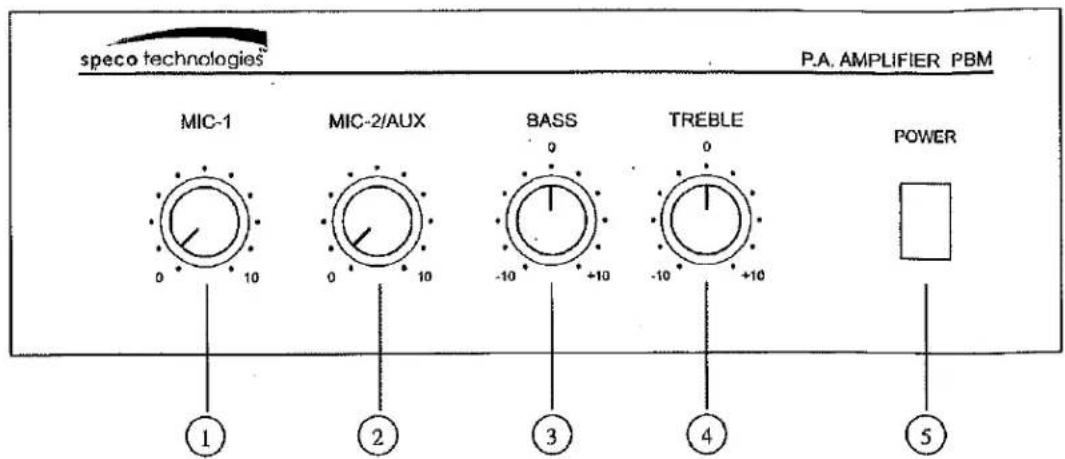
1) MIC-1 Volume control
2) MIC-2/AUX Volume control
3) BASS Control
REAR PANEL
1) AC accessory outlet (Unswitched)
2) AC fuse holder
3) MOH output level control*
4) MIC-2/AUX input selector switch
5) AUX input RCA jacks
6) TEL/PAGING output level control**
7) TEL/PAGING input terminals(Balanced)**
*MOH = Music on hold
**TEL/PAGING= Connection input terminals for general or emergency paging.
4) TREBLE Control
5) POWER on/off switch with indicator
8) MIC-1 input terminals(Balanced)
9) MIC-2 input terminals(Balanced)
10) Manual muting terminals
11) MOH output terminals*
12) Speaker outputs
13) Ground
14) AC power cord
**TEL/PAGING is not to be connected directly to a telephone circuit or TNV circuit.
FRONT PANEL
1) MIC-1 Volume control. Adjusts audio level of MIC-1.
2) MIC-2/AUX Volume control. Adjusts audio level of MIC-2/AUX.
3) Bass Control. Low frequency tone control.
4) Treble Control. High frequency tone control.
5) Power on/off switch with indicator. Illuminates when power is on.
REAR PANEL
1) AC accessory outlet (Unswitched). Unswitched AC Auxiliary outlet for a 120VAC. 50/60Hz power source.
2) AC fuse holder.
3) MOH output level control. Controls volume of MOH output. (Music on hold)
4) MIC-2/AUX input selector switch. Allows for selection of either low impedance MIC-2 input or high impedance AUX input.
5) AUX input RCA jacks. Provides connection for a booster amplifier. The input impedance of the equipment should be more than 600 Ohm.
6) TEL/PAGING output level control. Controls audio level of telephone output.
7) TEL/PAGING balanced input terminals. Accepts a balanced telephone paging signal.
8) MIC-1 balanced input terminals. Accepts a balanced low impedance microphone signal.
9) MIC-2 balanced input terminals. Accepts a balanced low impedance microphone signal.
10) Manual muting terminals. Provides contact closure muting of the MIC-2/AUX input during paging.
11) MOH output terminals. Provides two MOH outputs 600 Ohm, 1 Volt and 8 Ohm, 1 Watt.
12) Speaker outputs. Speaker lines must be connected to "COM" and one (and only one) of the remaining screw terminals.
13) Ground. Cabinet enclosure unit ground.
14) AC power cord. AC power cord with three pin plug for a 120VAC 50/60 Hz, power source. Do not defeat the ground pin.
Note: MIC-1/TEL input include internally adjustable (factory set) VOX muting of the MIC-2 and AUX input during paging.
Screw terminal designations : G-GND, HOT-Signal positive, COM-Signal negative/common.
Overcoming Ground Loop Problems
If the amplifier is mounted in a rack unit (Use rack mount part # PBM-RK1), or is used with equipment having its own ground, it is necessary to ensure that ground loops and the associated problems of hum on the output signal are not introduced by the ground wiring. (see warning)
Warning
To overcome this potential problem, the electrical and the mechanical ground on the amplifier may be separated by completely removing the wire connecting the power source to ground. CONSULT AN ELECTRONICS TECHNICIAN TO ACCOMPLISH THIS TO AVOID POTENTIAL PERSONAL INJURY OR A HAZARDOUS CONDITION.
SPEAKER CONNECTION
The rear panel of the amplifier contains a 7 screw terminal strip for connection of speakers. BE CAREFUL TO CONNECT SPEAKERS PROPERLY, see impedance and line voltage instructions below.
The speaker lines are connected directly between the appropriate COM terminal on the 7 screw terminal strip and the terminal corresponding to the impedance of the speaker(s) or of the line voltage selected.
4, 8 and 16 OHM CONNECTIONS (refer to figure 3).
Connect the cables to the terminals on the 7 screw terminal strip provided. Use the screw terminals which correspond to the impedance of the speaker(s). One lead must always be connected to the COM. This is just an example. If in doubt consult a qualified technician.


FIGURE 3
25V and 70V CONSTANT LINE VOLTAGE CONNECTIONS
(refer to figure 4).
IMPORTANT NOTICE: When the 25V and 70V constant line voltages are used, a line matching transformer must be used with each speaker. All transformers must be connected in parallel.
HOW TO CONNECT LINE MATCHING TRANSFORMERS IN PARALLEL
(25 VOLT LINE OR 70 VOLT LINE)
ALWAYS CONNECT LINE TRANSFORMERS IN PARALLEL
NEVER CONNECT LINE TRANSFORMERS IN SERIES

25V Transf.

70V Transf.
FIGURE 4
SPEAKER IMPEDANCES:
Speaker impedance taps for 4, 8 and 16 Ohm speakers are provided on a terminal strip on the rear panel of the unit. Also, outputs for 25V and 70V constant line voltage are provided. To connect the power output directly to a speaker or PA horn or a combination of speakers and/or PA horns which have a resulting voice coil impedance of 4,8 or 16 Ohm, connect to the COM and the proper impedance tap on the terminal strip. Be sure the speaker(s) or PA horn(s) is capable of handling a reasonable power output from the amplifier or permanent damage to the speaker(s) or PA horn(s) may result. Also, be careful not to overload the amplifier with too many speakers or PA horns. If it is desired to use a number and variety of speakers, the speakers must be arranged in various series or parallel arrays to provide proper impedance matching or the 25V or 70V constant line voltage must be used. If you are not familiar with impedance matching consult a professional installer or technician for advice. If the 25V or 70V constant line voltages are used, a line matching transformer must be used with each speaker. Again do not overload or use incompatible speakers. Line transformer are the preferred method for multi-speaker installation.
CABLE REQUIREMENTS
Output cabling need not be shielded in most cases and should be of sufficient gauge to minimize losses due to the resistance of the wire over long runs (insertion loss). Cable thinner than 18 gauge is not recommended. Long runs require 16 gauge or heavier.
In some cases, where the output cable is run in close proximity to unshielded intercom cables, electrical cables, radio transmission antenna or other sources of interference or when the amplifier is being used for paging from a telephone system, the amplifier may require shielded output cabling to prevent audio feedback or interference.
PRIORITY PAGE :THE AMPLIFIER FEATURES A VOICE ACTIVATED PRIORITY PAGE CIRCUIT AND AUTOMATICALLY MUTES ALL PROGRAM MATERIAL (TUNER/TAPE/CD,ETC.) FROM THE AMPLIFIERS OUTPUT AND PERMITS MICROPHONE # 1 AND THE TELEPHONE INPUT TO OVERRIDE FOR PAGING ANNOUNCEMENTS.
TELEPHONE LINE: A TELEPHONE LINE INPUT OF 600 OHM IS PROVIDED.
THERE ARE MANY OTHER FEATURES OFFERED. PLEASE READ MANUAL COMPLETELY.
WHENEVER IN DOUBT ABOUT INSTALLATION, CONSULT WITH A PROFESSIONAL INSTALLER OR TECHNICIAN OR PERSONAL INJURY, DAMAGE TO THIS AMPLIFIER AND/OR SPEAKERS MAY RESULT AND YOUR WARRANTY MAY BE VOIDED.
speco technologies™
Determining Your Amplifier Needs for Sound Systems
Step 1: Fill out Wattage Tap Requirement Chart (to right) determining the number of speakers that will be used at each wattage tap for the amplifier.
Step 2: Multiple the number of speakers by each wattage tap to determine Total Wattage Requirement per Tap setting (See Ex A).
Step 3: Add all the figures in shaded area to determine the total Wattage Requirement for the amplifier.
Step 4: Match total Wattage Requirement to the bottom chart "Recommended Amplifier Wattage Chart" to determine acceptable RMS Wattage your amplifier should have.
Step 5: Repeat this process for each amplifier system required.
Wattage Tap Requirement Chart
| Set Wattage Taps | Number of Speakers at Set Tap | Total Wattage Requirement per Tap Setting | ||
| Ex A) | 5 | X | 10= | 50 |
| 60 | X | = | ||
| 30 | X | = | ||
| 20 | X | = | ||
| 15 | X | = | ||
| 10 | X | = | ||
| 7.5 | X | = | ||
| 5 | X | = | ||
| 4 | X | = | ||
| 3.75 | X | = | ||
| 2.5 | X | = | ||
| 2 | X | = | ||
| 1.50 | X | = | ||
| 1.25 | X | = | ||
| 1.00 | X | = | ||
| 0.50 | X | = | ||
| 0.25 | X | = | ||
| 0.125 | X | = | ||
| Total Sum of Shaded Area Represents Total Wattage Requirement | ||||
Recommended Amplifier Wattage Chart
| 15 Watt | 30 Watt | 60 Watt | 120 Watt | |
| If Sum Wattage Total is 12 Watts or Less | X | X | X | X |
| If Sum Wattage Total is between 13 and 24 Watts | X* | X | X | X |
| If Sum Wattage Total is between 25 and 48 Watts | X* | X* | X | X |
| If Sum Wattage Total is between 49 and 96 Watts | X* | X* | X* | X |
| If Sum Wattage Total is between 97 and 204 Watts | X* | X* | X* | X* |
| If Sum Wattage Total is between 205 and 216 Watts | X* | X* | X* | |
| If Sum Wattage Total is between 217 and 240 Watts | X* | X* | ||
| If Sum Wattage Total is between 241 and 288 Watts | X* | |||
| * RMS Amplifier used in conjunction with Speco Technologies' P-240A Power Booster Amp | ||||
SPECIFICATIONS
| Type | Public Address Mixer Power Amplifier | |
| Model No. | PBM-15 | PBM-30 |
| Power supply | AC 120V, 50/60Hz | AC 120V, 50/60Hz |
| Rated output power | 15W RMS | 30W RMS |
| Frequency response | 50~15 KHz ±3dB | 50~15 KHz ±3dB |
| Total harmonic distortion | 1% or less at 1 KHz at rated output | 1% or less at 1KHz at rated output |
| Input sensitivity and impedance | TEL :100mV/600 Ohm, BalancedMIC-1:1.0mV/600 Ohm, BalancedMIC-2:1.0mV/600 Ohm, BalancedAUX:200mV/50K Ohm, Unbalanced | TEL :100mV/600 Ohm, BalancedMIC-1:1.0mV/600 Ohm, BalancedMIC-2:1.0mV/600 Ohm, BalancedAUX:200mV/50K Ohm, Unbalanced |
| S/N Ratio | MIC-1 Better than 55 dBMIC-2 Better than 55 dBTEL Better than 60 dBAUX Better than 70 dB | MIC-1 Better than 55 dBMIC-2 Better than 55 dBTEL Better than 60 dBAUX Better than 70 dB |
| Speaker outputs | 4 Ohm, 8 Ohm, 16 Ohm25V, 70V line outputs | 4 Ohm, 8 Ohm, 16 Ohm25V, 70V line outputs |
| *MOH output | 600 Ohm @ 1V and8 Ohm - 1Watt | 600 Ohm @ 1V and8 Ohm - 1Watt |
| Mute level | MIC-2/ AUX≥ 40 dB | MIC-2/ AUX≥ 40 dB |
| **VOX level | MIC-1/TEL 0~40 dB Adjustable** | MIC-1/TEL 0~40 dB Adjustable** |
| Tone control | Bass: ±10 dB at 100HzTreble: ±10 dB at 10KHz | Bass: ±10 dB at 100HzTreble: ±10 dB at 10KHz |
| Dimensions | 272mm(W)x88mm(H)x240mm(D)10.7"(W)x3.5"(H)x9.4"(D) | 272mm(W)x88mm(H)x240mm(D)10.7"(W)x3.5"(H)x9.4"(D) |
| Weight | Approx 8 lbs(3.7 kgs) | Approx 22 lbs (10.0 kgs) |
| Finish | Black | Black |
| Mounting options | Table top or 19"rack or wallmountable (Use # PBM-RK1 rackmount bracket) | Table top or 19"rack or wallmountable (Use # PBM-RK1 rackmount bracket) |
*MOH = Music on hold **Factory set : - 40 dB
- PUBLIC ADDRESS AMPLIFIER
- PBM-15
- PBM-30
- WATT RMS
- WATT RMS
- CAUTION
- PRECAUTIONS
- Unpacking
- Ventilation
- IMPORTANT SAFETY INSTRUCTIONS
- Controls and Connections
- FRONT PANEL
- REAR PANEL
- Overcoming Ground Loop Problems
- Warning
- SPEAKER CONNECTION
- HOW TO CONNECT LINE MATCHING TRANSFORMERS IN PARALLEL
- SPEAKER IMPEDANCES:
- CABLE REQUIREMENTS
- speco technologies™
- Determining Your Amplifier Needs for Sound Systems
Brand : Speco Technologies
Model : PBM30
Category : Audio Amplifier