
XG E - Video camera MINOLTA - Free user manual and instructions
Find the device manual for free XG E MINOLTA in PDF.


| Product Type | 35mm Single Lens Reflex (SLR) Camera |
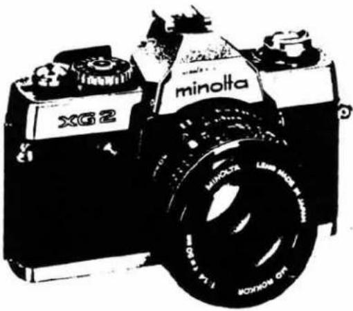
| Model | Minolta XG-E (XG E) |
| Lens Mount | Minolta MD / MC bayonet |
| Standard Lens | MD ROKKOR 50mm f/1.4, f/1.7 or f/2 (depending on version) |
| Exposure Control | Aperture-priority auto exposure; manual setting of shutter speeds |
| Shutter | Electronically controlled focal-plane; speeds Auto 1/1000–1 sec (stepless), Manual 1/1000–1 sec + B |
| Metering | TTL full-aperture, center-weighted; CdS cells (two) |
| Metering Range | EV 2–17 (ISO 100, f/1.4 lens) |
| Film Speed Range | ISO 25–1600 |
| Exposure Compensation | ±2 EV in 1/2-step increments |
| Viewfinder | Eye-level pentaprism; 93% frame coverage; 0.9× magnification; -1 diopter |
| Viewfinder Display | LED scale indicating shutter speed (auto) or set speed (manual) |
| Film Advance | Manual lever (130° stroke, 30° stand-off); optional auto winder (Minolta Auto Winder G) |
| Self-Timer | Electronic, approx. 10 sec; blinking LED (faster last 2.5 sec) |
| Flash Sync | X-sync at 1/60 sec; hot shoe + PC terminal; exclusive strobo auto setting |
| Battery | Two silver-oxide 1.5V cells (S-76, G-13 or equivalent) |
| Dimensions (Body only) | 138 × 88 × 52 mm (5.6 × 3.5 × 2.0 in) |
| Weight (Body only) | 505 g (17.8 oz) without battery |
| Accessories | Auto winder G, Auto electroflash 200X, remote cords (50 cm, 5 m) |
| Construction | Metal and high-impact resin body; removable back cover |
| Cleaning & Care | Use alcohol or flonsolve only; avoid thinners, ketones, ether; do not overtighten screws |
| Repairability | Service manual and parts lists available; shutter unit replaceable |
Frequently Asked Questions - XG E MINOLTA
User questions about XG E MINOLTA
0 question about this device. Answer the ones you know or ask your own.
Ask a new question about this device
Download the instructions for your Video camera in PDF format for free! Find your manual XG E - MINOLTA and take your electronic device back in hand. On this page are published all the documents necessary for the use of your device. XG E by MINOLTA.
USER MANUAL XG E MINOLTA
Shutter Parts List for XG series
natural_image
Circular black-and-white abstract pattern with horizontal white stripes (no text or symbols)MINOLTA
MINOLTA XG7 2006-100(2006-200)
MINOLTA XG2 2006-300(2006-400)
MINOLTA XG-E 2006-500(2006-600)
( ) Black body
TYPE
Electronic Auto Exposure Control 35 mm Focal Plane Shutter Single Lens Reflex Camera.
STANDARD LENS
MD ROKKOR 50 mm F 1.4 (2521)
MD ROKKOR 50 mm F 1.7 (2520)
MD ROKKOR 50 mm F2 (524)…for export
AE SYSTEM
Aperture priority system
SHUTTER
Electronic control lateral focal plane shutter
Shutter speed : Auto 1/1000\~1 sec. (Stepless) Manual 1/1000, 1/500, 1/250, 1/125, 1/60, 1/30, 1/15, 1/8, 1/4, 1/2, 1 sec. and B.
Release : Magnetic release (with release lock to suspend operation when battery voltage is too low or shutter speed exceeds 1/1000).
Dial : Click-stop rotary dial with A-position lock and ±2 EV exposure correction scale in Auto.
Self-timer : About 10 sec. operation. Started by shutter button with set-dial at SELF-TIMER. Electronic control. Operation is indicated by LED blinking at front of camera. Blinking cycle is faster after 7.5 sec.
Synchro contact : X contact (electro flash is tuned to longer sec. time than 1/60 sec.). MF, M and FP are tuned to longer sec. than 1/15 sec.
Synchro terminal: Hot shoe and JIS-B type socket (Electric shock proof)
Synchro auto control: With exclusive strobo (8658) mounted and charge completed, when shutter is automatically operated. exposure is at X-tuned speed (1/60) and then LED blinks in finder.
FILM FEED
Winding : Operation lever type. Winding angle 130°, reserve angle 30°.
Auto winding : Possible with exclusive auto winder (8731-200) mounted (at bottom of camera).
Spool : 4 claws to wind film reversely.
Film counter : Auto reset type calculator.
Film signal : Built-in
Re-winding : Re-winding button is automatically reset as a result of winding.
Back cover : Hinged, one-touch locking, removable type. Unlocked by rewinding knob operation.
natural_image
Black-and-white illustration of a minolta digital camera with visible lens and branding (no text or symbols on body)FINDER
Type : Eye level type (Pentagon prism)
Focal plate : Split image and micro prism for center, mat for periphery.
View rate : 93% (to 24×36mm standard image)
Magnification : 0.9 (at ∞ with 50 mm standard lens)
Visibility : -1 diopter
Indication in finder: Exposure indication by LED (two-print indication represents "intermediate"); shutter speed scale.
High-speed non-interlocking LED (shutter doesn't operate when LED is on).
Exclusive strobo complete charge and X auto setting are indicated by LED blinking.
Mirror : Quick return system. PO value: 123 (to standard picture)
EXPOSURE CONTROL
Metering system : Full-aperture TTL metering, central-zone weighted (overall) metering type.
Light receiving element: CdS (on both sides of eye-piece)
Auto exposure range: EV 2\~17 (ASA 100, F 1.4 lens)
ASA sens. interlock range: ASA 25-1600 (shutter dial pull-up).
Exposure correction: Stepless up to ±2 EV to standard value (with lock at standard position, clicking every 1/2 step).
Exposure meter switch: Touch switch type (ON when shutter button is touched). When touched with gloved hand, it is ON at the 1st step of shutter button (about 0.5mm stroke).
Power source : 2 silver oxide batteries (equivalent to JIS-G13) S-76 (SONY EVEREADY) G-13 (NATIONAL, HITACHI, TOSHIBA) S-76 (EVEREADY) U. S. A. Europe MS-76 (MALLORY) RS-76 (RAY-O-VAC)-U. S. A.
Power supply switch:
ON with shutter button depressed (changeover switch provided separately). (ON: Ready for operation, OFF: Metering circuit OFF, no shutter operation)
Battery check : Set changeover switch to B.C. and check by LED at front of camera. It is reset when released.
OTHERS
• Film signal attached
• Memo holder attached
EXCLUSIVE ACCESSORIES
• Auto winder G
• Auto electroflash 200X
• Remote cord S 50 cm (20-in)
• Remoto cord L 5m (16-ft.)
DIMENSIONS
Size (body only): 138(L) × 88(H) × 52(W) mm 5-5/8(L) × 3-7/16(H) × 2(W) in.
Weight : 505g (excl.battery) 17-13/16 oz.
Description of Mechanism
Page
- Winding Mechanism.... 1
- Winding Lever Operation 3
- Shutter Dial Mechanism 3
A. Auto/Manual/Bulb changeover 3
B. Film sensitivity setting 4
C. Exposure correction 5
D. Release switch 6
- Magnetic Release Mechanism 7
5.Shutter Mechanism 9
A. Charge mechanism 9
B. Release mechanism 9
C. X contact mechanism 11
D. Mirror preset reset mechanism 12
- Mirror Box Mechanism 12
A. Mirror (45°) retaining mechanism 12
B. Mirror raising and lowering mechanism 13
C. Preset mechanism.... 14
- Principle of Metering and Description of Circuit 15
A. Outline 15
B. General description 15
C. Description of circuit 19
- Mode selector circuit 19
- Metering switch (Touch switch) 19
- Voltage detecting circuit 19
- Metering operation circuit 19
- Indication circuit 20
- Magnetic release 21
- Over-range lock 21
- Memory circuit 21
- Logarithmic expansion circuit 22
- Control circuit 22
- Power source holding circuit 22
- Bulb mode 23
- Magnetic self 23
- Remote control 23
- Winder control function 24
- Strobo Auto 24
- XG Time Chart 25
D. Circuit diagram and Switch characteristics 26
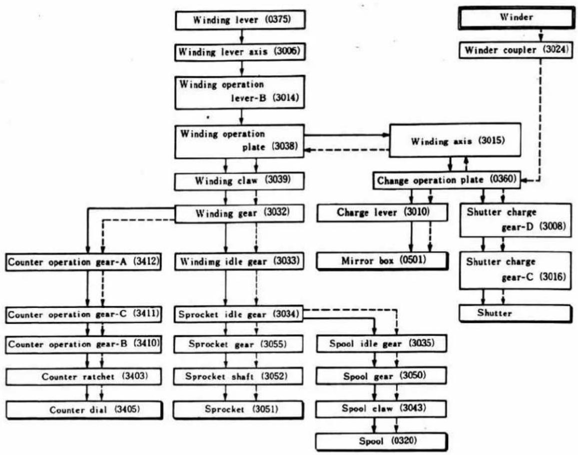
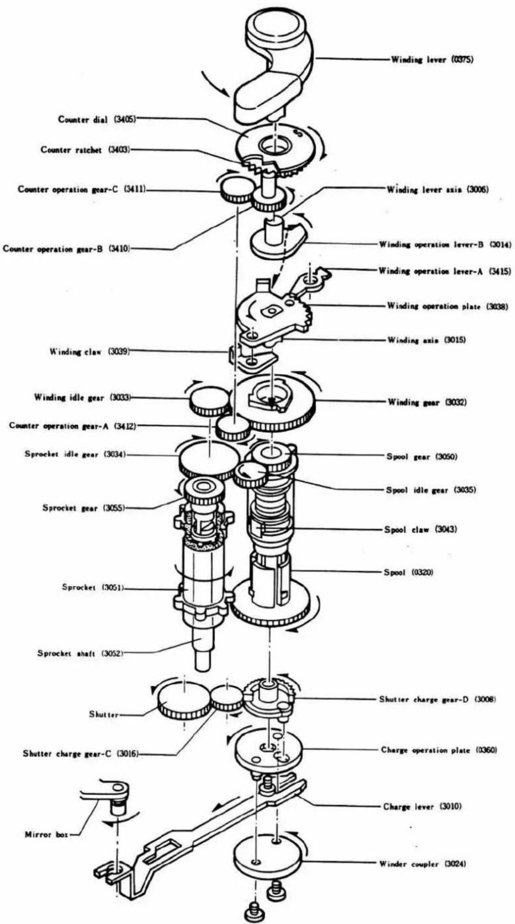
1. Winding Mechanism
〈Operating Order〉
(Arrows show interlocking marks)
Manual winding
←---- Winder
flowchart
graph TD
    A["Winding lever (0375)"] --> B["Winding lever axis (3006)"]
    B --> C["Winding operation lever-B (3014)"]
    C --> D["Winding operation plate (3038)"]
    D --> E["Winding claw (3039)"]
    E --> F["Winding gear (3032)"]
    F --> G["Winding idle gear (3033)"]
    G --> H["Sprocket idle gear (3034)"]
    H --> I["Sprocket gear (3055)"]
    H --> J["Sprocket shaft (3052)"]
    H --> K["Sprocket (3051)"]
    D --> L["Winding axis (3015)"]
    L --> M["Change operation plate (0360)"]
    M --> N["Charge lever (3010)"]
    M --> O["Shutter charge gear-D (3008)"]
    O --> P["Shutter charge gear-C (3016)"]
    P --> Q["Shutter"]
    R["Winder"] --> S["Winder coupler (3024)"]
    S --> L
    T["Counter operation gear-A (3412)"] --> F
    U["Counter operation gear-C (3411)"] --> F
    V["Counter operation gear-B (3410)"] --> H
    W["Counter ratchet (3403)"] --> H
    X["Counter dial (3405)"] --> H
    Y["Spool (0320)"] --> K
(Parts which require positioning)
Winding gear (3032) ← → Winding idle gear (3033)
Sprocket gear (3055) ← → Sprocket idle gear (3034)
Counter operation gear-B (3410) ← → Counter ratchet (3403)
Shutter charge gear-C (3016) ← → Shutter
- Winding operation plate (3038) is stopped by winding operation lever-A (3415) during winding, and then winding shaft (3015) does not return.
• Winding lever (0375) can be stored even during winding. - Sprocket (3051) is turned 1-1/3 times and the spool once when winding lever is operated once.
- With the winding lever pulled out up to the allowance angle when winder is used, continuous winding is impossible unless the winding lever is released.
2. Winding Lever Operation
Winding operation lever-A position (158°40')
Reversing stop claw action start (158°20')
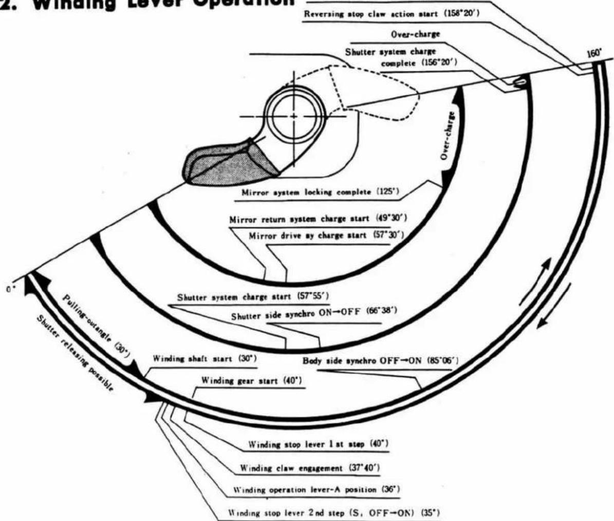
flowchart
graph TD
    A["Shutter releasing possible"] --> B["Winding gear start (40°)"]
    B --> C["Winding shaft start (30°)"]
    C --> D["Shutter system charge start (57°55′)"]
    D --> E["Mirror return system charge start (49°30′)"]
    E --> F["Mirror drive by charge start (57°30′)"]
    F --> G["Shutter system locking complete (125°)"]
    G --> H["Over-charge"]
    H --> I["Shutter system charge complete (156°20′)"]
    I --> J["Reversing stop claw action start (158°20′)"]
    J --> K["Over-charge"]
    K --> L["Body side synchro OFF→ON (85°06′)"]
    L --> M["Winding stop lever 1st step (40°)"]
    M --> N["Winding claw engagement (37°40′)"]
    N --> O["Winding operation lever-A position (36°)"]
    O --> P["Winding stop lever 2nd step (S, OFF→ON) (35°)"]
    P --> Q["Pulling-outangle (30°)"]
    Q --> R["0°"]
    R --> S["160°"]
3. Shutter Dial Mechanism
The shutter speed dial of XG is provided with Auto/Manual changeover, film sens. setting, exposure correction and release switch mechanisms.
〈Operation〉
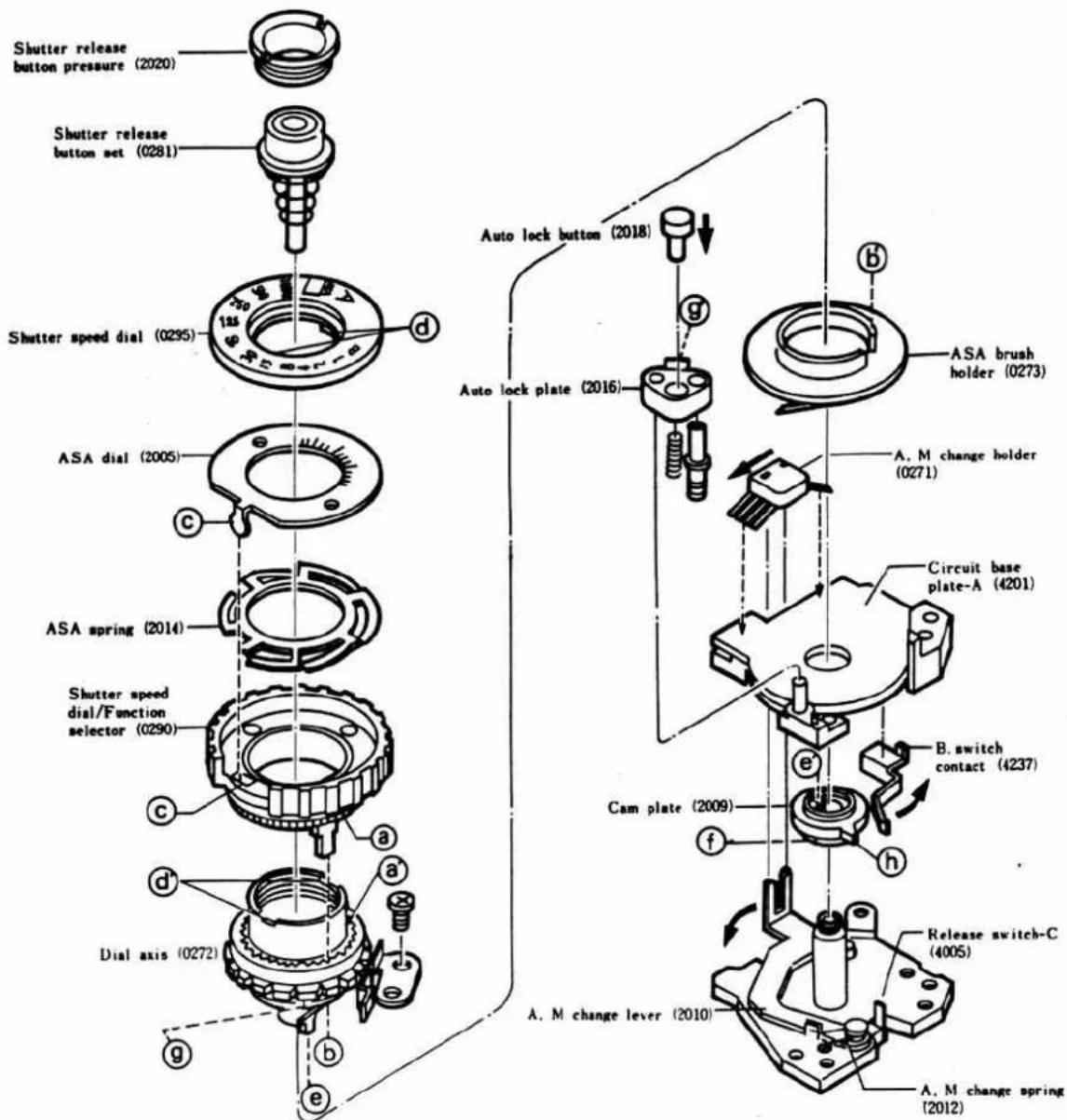
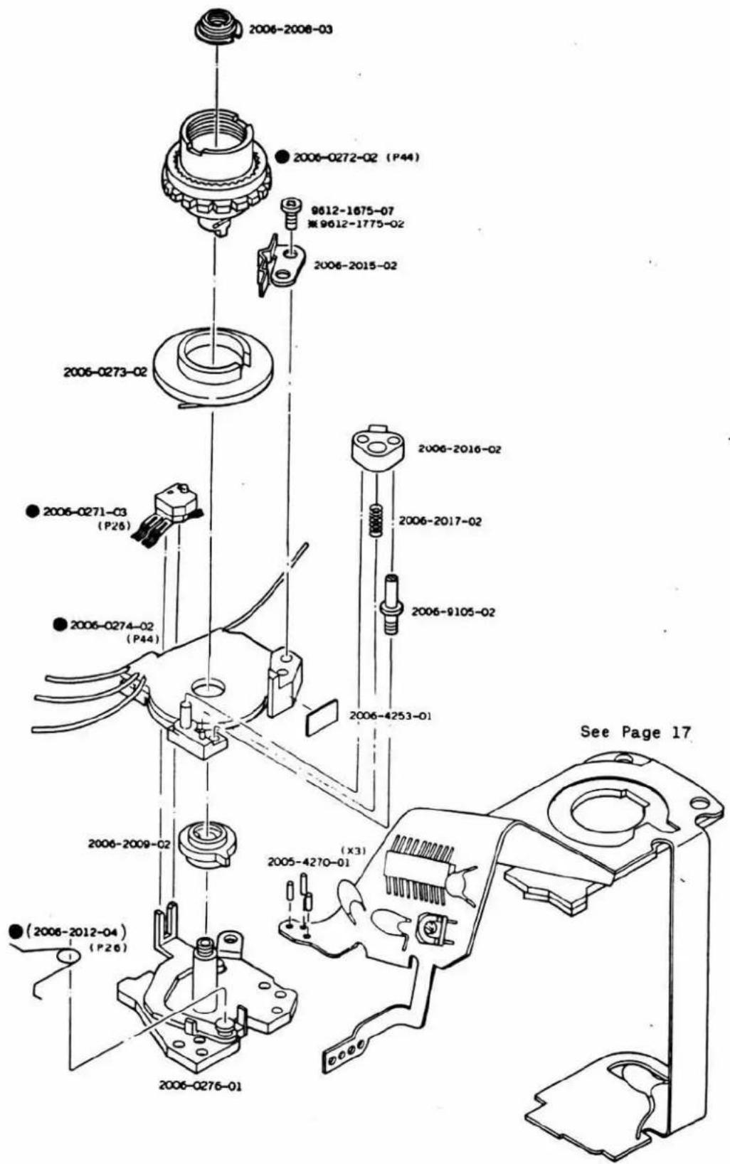
- Shutter speed dial (0290) is usually engaged with dial shaft (0272), ASA brush holder (0273), and ASA dial plate (2005) respectively at aa', bb' and cc'. The dial then rotates along with each of the parts.
- Further, dial shaft (0272) is engaged with shutter speed dial plate (0295) and cam plate (2009) respectively at dd' and ee', and then rotates along with shutter dial (0290).
- With shutter speed dial (0290) lifted up, it is only disengaged from dial shaft (0272) at aa', and ASA brush holder (0273) and ASA dial plate (2005) rotate along with the shutter speed dial, but dial shaft (0272), shutter speed dial plate (0295) and cam plate (2009) do not rotate.
A. Auto/Manual/Bulb changeover
- When shutter speed dial (0290) is set to Auto "A", cam plate (2009) being engaged with dial shaft (0272) at ee' rotates, then AM change lever (2010) operates at cam face ① in the direction of the arrow and AM change switch (S 8. S 10) of AM change holder is shifted to AUTO side of circuit board A (4201), simultaneously ⑧ of dial shaft (0272) is locked by ⑨ of auto lock plate (2016).
-
When auto lock plate (2016) is released from dial shaft (0272) by pressing auto lock button (2018) in the direction of the arrow, thus setting shutter speed dial (0290) to an optional position, cam face (f) of cam plate (2009) being engaged with dial shaft (0272) is also moved, and AM change lever (2010) is operated by the function of AM change spring (2012) in the opposite direction to the arrow and AM change switch (S 8 S 10) is then shifted to the manual side of circuit board (4201).
-
When shutter speed dial (0290) is set to "B" position, B switch contact (4237) is pushed by projection of cam plate (2009) in the direction of the arrow, and then valve switch (S5) including release switch C (4005) is turned OFF.
B. Film sensitivity setting
-
Film sensitivity can be set by lifting and turning shutter speed dial (0290) and setting it to the ASA sensitivity.
-
When shutter speed dial (0290) is lifted up, it is disengaged from dial shaft (0272) at as'. Then dial shaft (0272) is not rotated but ASA dial plate (2005) and ASA brush holder (0273) rotated.
And the ASA brush of ASA brush holder (0273) is set to the position on the sliding resistance of circuit board A (4201) corresponding to the sensitivity value of ASA dial plate (0295).
C. Exposure correction
-
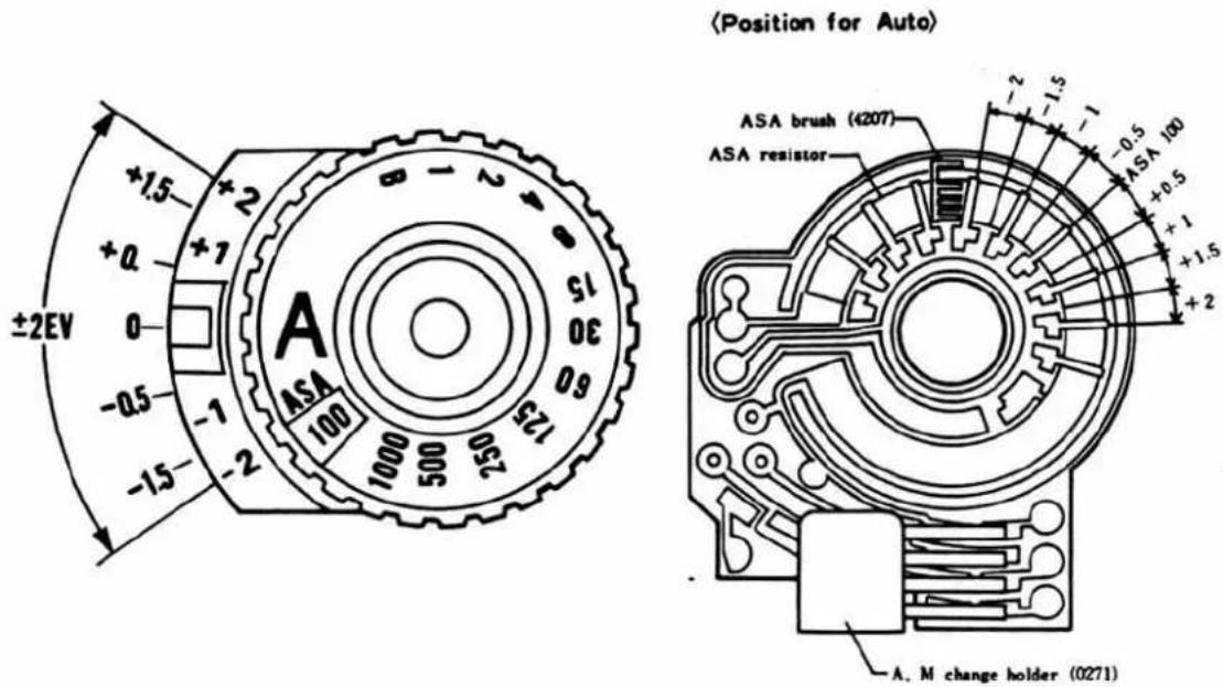
Dial shaft (0272) is provided every 0.5 EV with click grooves up to ±2.0 EV from AUTO "A" position of shutter speed dial/Function selector. Exposure correction can be done by releasing auto lock plate (2016) and by setting "A" of shutter speed dial/Function selector (0290) to the desired position. At that time, cam plate (2009) is also rotated, but AM change lever (2010) is on cam face f, and AM change switch (S8, S10) of AM change holder (0271) is on the AUTO side.
-
In accordance with the exposure correction setting, the ASA brush of ASA brush holder (0271) moves on the ASA resistance of circuit board A (4201), then auto exposure and shutter speed indications are changed corresponding to the amount of correction.
D. Release switch
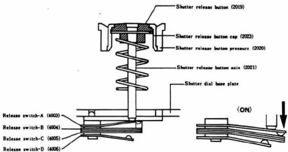
- Shutter release button set (0281) passes through the center of shutter speed dial. Shutter button shaft (2021) comes in contact with release switch A (4003), and is maintained by shutter button holder (2020).
- Shutter button shaft (2020) is separated from shutter button cap (2023) by the insulator of shutter button (2019), thus forming touch switch (S 11).
- Release switch A (4003), B (4004), C (4005) and D (4006) are secured on shutter speed dial base plate (0384). Metering switch (S1) is formed by release switch A (4003) and B (4004); and release switch (S2) is formed by release switch C (4005) and D (4006). When shutter button set (0281) is pressed, these switches are turned ON in order, thus starting the operation of the circuit.
4. Magnetic Release Mechanism
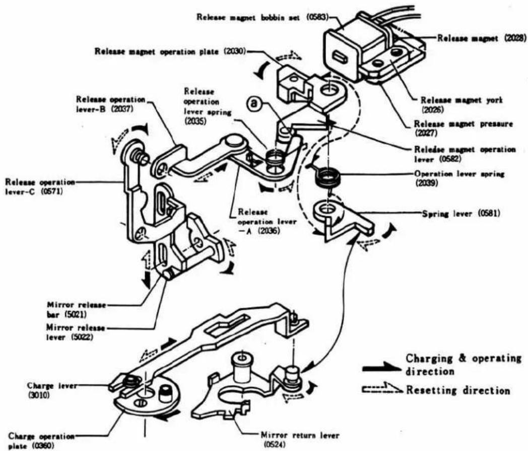
- Winding operation causes charge operation plate (0360) and charge lever (3010) being engaged with the plate to be shifted in the direction of the arrow.
- Further, mirror return lever (0524) being engaged with charge lever (3010) is moved in the direction of arrow to push spring lever (0581) in the direction of arrow, thus charging operation lever spring B (2039) and completing the preparations for release.
〈Operation〉
- Release magnet operation plate (2030) is maintained being attracted by release magnet (2028) via release magnet york (2026) and release magnet retainer (2027).
- When shutter release button set (0281) is pushed, the electric circuit operates. Then a magnetic field opposite to that of release magnet (2028) is generated at release magnet bobbin (0583) attached to release magnet york (2026), and current instantaneously flows due to the discharge of condenser.
- Consequently, release magnet operation plate (2030) becomes unbalanced in attraction, then released by the function of operation lever spring (2039) and shifted in the direction of arrow.
- Release operation lever A (2036), B (2037), C (0571) and mirror release bar (5021) are operated in order via ⑧ of release magnet operation lever (0582), then mirror release bar (5021) pushes mirror release lever (5022) in the direction of arrow thus release the mirror system and allowing the mirror preset system to operate.
〈Return〉
- When mirror return lever (0524) has returned to the original position with exposure completed, spring lever (0581) retained by mirror return lever (0524) becomes free.
- On returning of mirror return lever (0524), charge lever (3010) and release operation lever spring (2035) also return in the direction of dashed line.
- Release operation lever spring (2035) pushes release operation lever-A (2036) and operates release magnet operation lever (0582) in the direction of arrow, then presses release magnet operation plate (2030) against release magnet york (2026).
- Operation of release operation lever-A (2036) in the direction of dashed line causes release operation lever-B (2037), C (0571), mirror release bar (5021) and mirror release lever (5022) to return in the direction of dashed line, thus getting ready for the next charge.
Magnetic Release Operation by Remote Cord
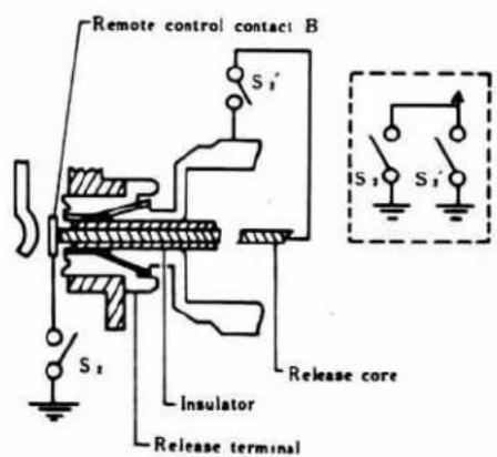
When the remote cord is connected to the release terminal as illustrated, the release core is electrically connected to the remote control contact B, and then release switch (S₂) and remote cord switch (S₂') are connected in parallel to each other. The magnetic release is operated when remote cord switch (S₂') is turned ON.
The shutter speed indication can be checked by setting touch switch (S 11 ) or metering switch (S 1 ) to ON.
9
5. Shutter Mechanism
- The shutter of XG employs only electric control for the shutter speed control and only "X" for the synchro mechanism, thus making its mechanism very compact.
- The shutter curtain runs laterally and the curtain shaft employs a single shaft system. Also, an OFF-type trigger contact is used and all parts are set up into one unit.
A. Charge mechanism
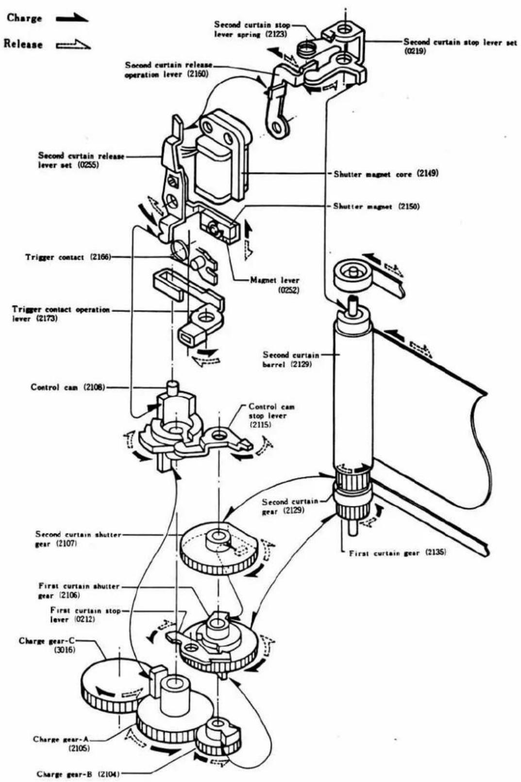
- Winding operation causes charge gear A (2105) being engaged with shutter charge gear C (3016) on body side to rotate in the direction of arrow.
- As charge gear B (2104) being engaged with charge gear A (2015) rotates, first curtain shutter gear (2106) and second curtain shutter gear (2107) rotate in the direction of arrow.
- First curtain gear (2135) and second curtain gear (2129) being engaged with first curtain shutter gear (2106) and second curtain shutter gear (2107) rotate in the direction of arrow, charging the 1st and 2nd curtains.
- Oo the other hand, control cam (2108) is rotated for charge during rotation of charge gear A (2105) in the direction of arrow.
- Operation of control cam (2108) in the direction of arrow causes first curtain stop lever (0212) to be released so that the stop lever can rotate by its spring strength in the direction of arrow to stop the first curtain shutter gear.
- Further, control cam (2108) operates trigger contact operation lever (2173) in the direction of arrow to turn on trigger contact (2166) and operate second curtain release lever (0255) in the direction of arrow to press shutter magnet (2150) against shutter magnet core (2149).
- Operation of second curtain release lever (0255) in the direction of arrow causes second curtain lever (2160) and second curtain stop lever (0219) to be operated in the direction of arrow by second curtain lever spring (2163) and second curtain stop lever spring (2123). Then second curtain stop lever (0219) is able to stop second curtain barrel.
- First curtain shutter gear (2106) is stopped by first curtain stop lever (0212), control cam (2108) by control cam stop lever (2115) and second curtain barrel (2129) by second curtain stop lever (0219). Shutter magnet core (2149) is pressed against shutter magnet (2150) and then trigger contact (2166) is ON thus completing the charge.
- When the winding lever has returned to the original position, charge gear A (2105) and B (2104) also return to the pre-charge positions, thus completing the preparations for release.
B. Release mechanism
- When the shutter button is operated, the preset interlocking lever on the mirror box side operates control cam stop lever (2115) in the direction of dashed line just before the end of operation of the mirror preset system, thus releasing control cam (2108).
- Control cam (2108) is rotated in the direction of dashed line by the function of spring to operate first curtain stop lever (0212) in the direction of dashed line thus releasing it from first curtain shutter gear (2106), then it is rotated in the direction of dashed line by the function of the first curtain spring, allowing the first curtain to start running and exposure.
- Oo completion of counting at the electric circuit, the current to the magnet is cut off. Shutter magnet core (2149) is released from shutter magnet, and magnet lever (0252) is operated in the direction of dashed line by the function of spring. Then second curtain release lever (0255), second curtain lever (2130) and second curtain stop lever (0219) are operated in the direction of dashed line in order, allowing the second curtain to start running to complete exposure.
C. X contact mechanism
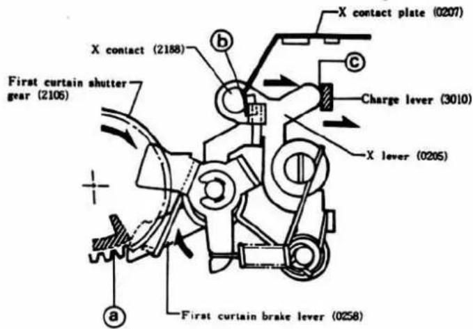
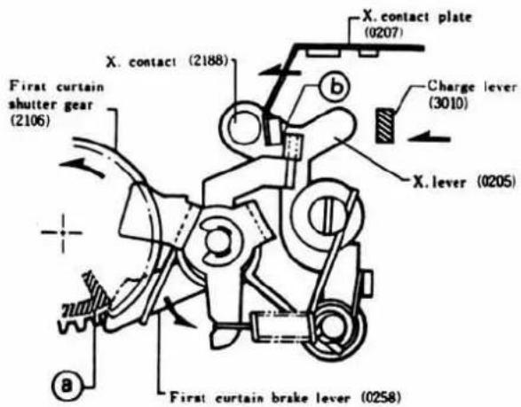
- When first curtain shutter gear (2106) is rotated in the direction of arrow, first curtain brake lever (0258) having been pushed up at ⓐ is operated in the direction of arrow by spring, then X contact plate (0207) completes the preparation for operation.
- On the other hand, operation of charge lever (3010) on body side in the direction of arrow causes X lever (0205) having been pushed at © to be operated in the direction of arrow by spring, then X contact (2188) also completes the preparation for operation.
〈Operation〉
- As the first curtain runs, first curtain shutter gear (2106) rotates in the direction of arrow and pushes first curtain brake lever (0258) at ④ of first curtain shutter gear (2106) just before the end of rotation (just before completion of 1st curtain running).
- First curtain brake lever (0258) pushes X contact plate (0207) at ⑥ in the direction of arrow, then X contact (2188) and X contact plate (0207) are ON.
- When the mirror return lever on the mirror box side has returned to the original position, body side charge lever (3010) operates in the direction of arrow to shift X lever (0205) in the direction of arrow, then X contact (2188) is separated from X contact plate (0207) to become OFF.
11
-
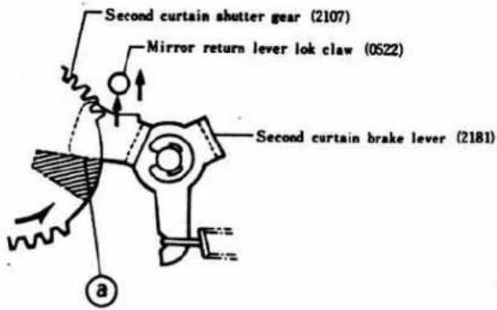
As the second curtain runs, second curtain shutter gear (2107) rotates in the direction of arrow and pushes second curtain brake lever (2181) at ⑧ of second curtain shutter gear (2107) just before the end of rotation (just before completion of 2nd curtain running).
-
Second curtain brake lever (2181) kicks mirror return lever lock claw (0522) on the mirror box side to reset the mirror preset system.
6. Mirror Box Mechanism
A. Mirror (45°) retaining mechanism
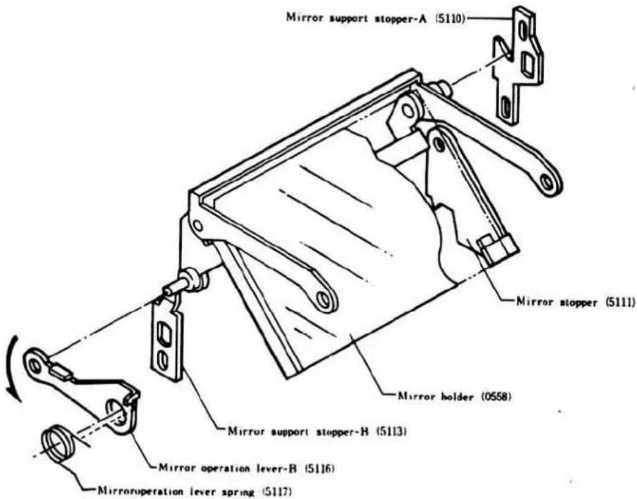
Mirror operation lever B (5116) is free before and after winding. It is pushed down by mirror operation lever spring (5117), then mirror holder (0550) being engaged with mirror operation lever (5116) is retained at 3 points of mirror stopper (5111), mirror support A (5110) and B (5113), thus keeping the mirror angle at 45°.
B. Mirror raising and lowering mechanism
〈Raising〉
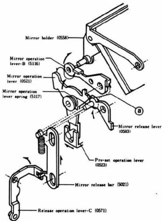
- Operation of release magnet causes mirror release bar (5021) being engaged with release operation lever C (0571) to operate in the direction of the arrow. Then it is disengaged from mirror operation lever (0521) at ⓐ, and mirror-up spring (5042) moves preset operation lever (0523) and mirror operation lever (0521) in the direction of the arrow.
- Operation of mirror operation lever (0521) causes mirror operation lever-B (5116) to operate in the direction of the arrow. Then mirror holder (0558) being engaged with mirror operation lever-B (5116) is raised.
〈Lowering〉
- When the second curtain has completed running, preset operation lever (0523) is returned in the direction opposite to the arrow, and mirror operation lever (0521) is also returned. Then mirror operation lever-B (5116) is returned by mirror operation lever spring (5117) along with mirror operation lever (0521), and then mirror holder (0558) is lowered.
- On the other hand, the release magnet is returned on returning of preset operation lever (0523), then release operation lever-C (0571) is operated in the direction opposite to the arrow, and mirror release bar (5021) and mirror release lever (0503) are returned by spring, thus stopping mirror operation lever (0521).
C. Preset mechanism
〈Operation〉
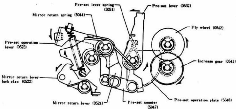
- Operation of the release magnet causes preset operation lever (0523) to operate in the direction lever (0523) to operate in the direction of the arrow. Then preset lever (0532) and preset operation plate (5048) are operated in the direction of the arrow via preset connector (5047). Thus the mirror is raised at the same time with stopdown operation.
- The rotation of preset operation plate (5048) is transmitted to flywheel (0542) via speed increase gear (0541), thus controlling the entire system.
〈Returning〉
- On completion of the second curtain running, mirror return lever lock claw (0522) is kicked in the direction of the arrow, releasing it from mirror return lever (0524), and then preset operation lever (0523) is returned along with mirror return lever (0524) by the function of mirror return spring (5044), and also preset operation plate (5048) is returned via preset connector (5047), thus the mirror is lowered.
- As preset connector (5047) operates, preset lever (0532) is returned by preset lever spring (5051) in the direction opposite to the arrow, then the diaphragm is released.
7. Principle of Metering and Description of Circuit
A. Outline
- Function
The electric circuit of XG has various functions as follows:
1) Automatic exposure control and shutter speed indication by LED.
2) Manual exposure control.
3) Shutter sec. time auto changeover and blinking indication by exclusive strobe.
4) Bulb exposure control.
5) Touch switch.
6) Magnetic release.
7) Electronic self-timer and blinking interval variable indicator circuit.
8) Voltage detection (incl. B.C)
9) Winder control.
- Composition
The circuit of XG is complicated having a lot of functions, and therefore solid-state construction is employed as much as possible for the circuit. It basically consists of two monosyllic ICs with 20 pins each for metering, operation, control (IC 1), and for indication (IC 2), one monosyllic IC with 10 pins mainly for self-timer (IC 3), and hybrid IC (HIC) for the purpose of connection between magnetic release and each circuit. To cope with such complicated wiring, a flexible circuit board is employed.
The switches are also transistorized as much as possible. Trigger switch, the representative one of mechanical switches, is of OFF type to minimize the influence of chattering. For the brushes of sliding resistors such as ASA resistor and diaphragm resistor, the number of brushes is increased in order to reduce noise. Also, 12 LED's are built into the indication board as indication elements.
B. General description
- Metering system
XG is a single-lens reflex camera using TTL metering system. And the amount of light to CdS is changed and shut off due to camera operations (such as auto exposure control and mirror operation).
It is therefore necessary for the camera to memorize the result of TTL metering (exposure time in XG) just before release.
- Memory system
XG employs such a system that both in auto and manual the exposure time is converted into an electrical amount (voltage) and it is charged into a condenser and then the charge voltage is memorized by the camera. Also, the system is to memorize logarithmic values because the metering range and film sensitivity interlocking range are wide; interchangeability is required for lenses and parts, making the circuits complicated; and the range of memorized values (exposure time) is also very wide.
- Metering switch
In order to prevent wasting of the battery due to forgetting to turn off the metering switch, the metering switch is interlocked with the release button. A touch switch is installed to improve the maneuverability during metering. (A touch switch uses a part (finger) of the user's body as a switch contact. So, when the user wears gloves, the finger will not serve as a contact. In that case, pressing the shutter button by one step more will turn on the metering switch.
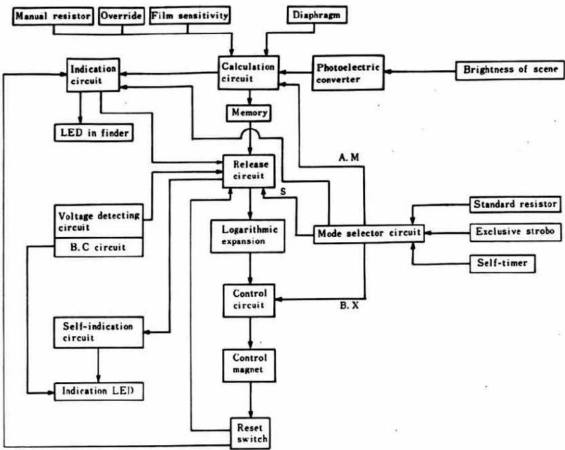
Each mode of XG is described in accordance with the block diagram.
flowchart
graph TD
    A["Manual resistor"] --> B["Indication circuit"]
    C["Override"] --> B
    D["Film sensitivity"] --> B
    E["Diaphragm"] --> F["Calculation circuit"]
    G["LED in finder"] --> B
    H["Voltage detecting circuit"] --> I["Release circuit"]
    J["Self-indication circuit"] --> K["Indication LED"]
    L["Logarithmic expansion"] --> M["Control circuit"]
    N["Mode selector circuit"] --> O["Control magnet"]
    P["Standard resistor"] --> Q["Exclusive strobo"]
    R["Self-timer"] --> S["B.X"]
    T["Memory"] --> U["Release circuit"]
    V["Diaphragm"] --> W["Photoelectric converter"]
    X["Brightness of scene"] --> Y["Calculation circuit"]
    Z["S"] --> U
    AA["A.M"] --> U
    AB["B.X"] --> AC["Control circuit"]
    AD["Reset switch"] --> AE["Indication LED"]
• Automatic exposure control system
1. Metering system
In the auto exposure control system of XG, the film sensitivity, aperture, and exposure correction value are preset. The exposure time is automatically determined according to these values and the brightness of the scene to achieve the appropriate exposure.
When metering switch (S₁ or S₁₁) is turned on, the film sensitivity and exposure correction values are mechanically added, and the values are converted into resistances, making the rotating angle constant per step, and the aperture value is also converted into a resistance value (logarithmic operation). These electrical amounts (resistances) and the brightness of the scene are treated by the photoelectric converter consisting two CdS and resistors, and the resultant electrical amount (resistance) is put into the calculation circuit. (The converted value (brightness of scene) is subjected to logarithmic compression during calculation.)
The result of calculation is an electrical amount (voltage) corresponding to the exposure time, which is charged into condenser (C_1) . Then, the exposure time is indicated in the finder by LED through the indication circuit.
The calculation in the above is as follows:
$$ \mathrm{TV} = (\mathrm{BV} - \mathrm{AV} _ {0}) + \mathrm{SV} - \mathrm{P} $$
TV : Shutter speed
BV : Brightness of scene
AV_0 : Max. aperture value
SV : Film sensitivity
P : Number of steps for set aperture
2. Control system
The control system of XG is more complicated than that of XE because XG employs a system that the desired exposure is achieved when the shutter is released.
When release switch (S₂) is operated, the release circuit operates to check to see that the shutter sec. time is within the interlocking range. At the same time, the power source voltage is checked by the voltage detecting circuit. And only when the conditions are satisfactory, the release magnet is operated to start the mirror system. On operation of the release magnet, the memory circuit operates to store the voltage corresponding to the exposure time at that point into condenser (C₁) for memory.
Even when the light to CdS is changed and shut off due to auto exposure control or mirror operation, the charge voltage already stored in the condenser will not be affected at all. As the operation is further performed, the first curtain starts running and the trigger switch operates in connection with the first curtain, then the control circuit operates to change the stored voltage into logarithmically expanded current.
Condenser (C₂) is charged with the current, and when the charge voltage reaches a certain level, the current of shutter control magnet is cut off by the function of the control circuit, then the second curtain runs to complete the exposure. When the exposure is completed, the mirror system is reset and the winding stop is released.
The circuit reset switch (S _4 ) being interlocked with the winding stop turns off to reset the release circuit.
The indication LED turns off with S_2 turned on. When the release button is kept depressed, LED turns on again with reset switch ( S_4 ) OFF.
- Manual sec. time
When the speed dial is set to 1\~1/1000 sec., the mode selector operates and the standard resistor is set instead of CdS, then the film sensitivity and override resistance are changed over to manual resistor. Also, the diaphragm resistor is released from the circuit and the power supply to the indication circuit is cut off, hence the indication LED does not light up.
When metering switch (S₁ or S₁₁) is turned on, the calculation is performed by the standard resistor and manual resistor, then voltage corresponding to the set sec. time is charged into condenser (C₁). Next, when release switch (S₂) is turned on, the power source voltage is checked by the voltage detecting circuit, then the release magnet is operated. The operations, after that, are the same as for the control system in auto mode.
When XG is used with manual sec. time, shutter sec. time is memorized. So, the shutter is controlled at the initially set speed even when the set speed is changed during shutter operation.
- Bulb mode
When the speed dial is set to "B", the mode selector operates to turn off the power source holding circuit, and power supply to the indication circuit is also cut off, then the indication LED does not light up. Next, when release switch (S₂) is turned on, the power source voltage is checked by the voltage detecting circuit, and then the release magnet is operated. As the operation continues, the trigger switch operates, but the bulb is given priority by (S₃) over control circuit, therefore, the shutter control magnet keeps operating while the release button is depressed, then the second curtain is stopped. When the release button is returned to the original position, release switch (S₂) is turned off and the power source holding circuit is also off, therefore, the shutter control magnet turns off thus completing the exposure.
- Strobe auto
When the exclusive strobo has been completely charged, the mode selector circuit is shifted to Strobo Auto, then the signal from the strobo enters the indication circuit and control circuit; blinking indication of "60" is given by the indication circuit and the exposure at the strobo-tuned speed (1/60) is done by the control circuit when the shutter is released. (When the bulb is used, however, the auto changeover to the tuned speed is not performed by the function of the mode selector.)
Indication…When used in auto mode, auto sec. time is indicated until completion of charge, but the changeover operation of the mode selector causes the indication signal on the camera side to turn off, and then "60" is turned on and off by the signal on the strobo side. When used in manual mode, the indication is off, therefore the indication "60" is turned on and off by the signal on the strobo side on completion of strobo charging.
Speed auto changeover…When released on completion of strobo charging, the releasing magnet operates to start the first curtain. At that time, the control circuit instantaneously operates to turn off the control magnet with the strobe signal, but the control magnet is kept ON by the strobo signal. As the operation continues, the synchro switch turns on when the first curtain nearly completes its running, then the strobo flashes, the signal from the strobo to the control magnet stops, the control magnet turns off, then the second curtain runs and the mode selector also returns to the original position.
- Electronic SELF
When the SELF changeover switch is set to "SELF", the mode selector operates to change the composition of the release circuit to the circuit for self-timer.
When release switch (S₂) is operated, the self-circuit operates and then LED for SELF operation indication (LED for B.C indication is used) blinks at constant intervals.
After release switch operation, the release circuit operates 8\~12 seconds later to release the shutter. Then the signal is given to the self indicator circuit by the release circuit (self circuit) 1/4 (about 2.5 sec.) before the total self-time length.
The self-timer operation indicating LED then blinks at faster intervals, thus giving a previous notice for shutter release.
- Transistor switch
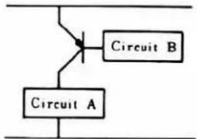
A conventional mechanical switch was operated by the movement of the release button or mirror, and the setting was maintained mechanically. Chattering was liable to occur when the switch turned on in particular. In the case of a transistorized switch, having a composition as illustrated below, the input (from circuit B) is electrically applied to the transistor to turn on and off. Also, the setting is retained by maintaining the input level. Since a transistor switch has no contact, it does not include mechanically operating parts and assures excellent durability being free from chattering.
C. Description of circuit
The circuit of XG is explained in accordance with the block diagram.
1. Mode selector circuit
This is the general name for circuits which select the mode in accordance with the switch operation or external signal (signal from strobo).
Auto mode: S_8 , S_9 , S_10 ……A side S_5 ……ON
Manual mode: S_0 , S_1 , S_10 ……M side S_3 ……ON
Bulb mode: S_8 , S_9 , S_10 ……M side S_5 ……OFF
Exclusive strobo mode:
On completion of strobo charge, the shutter speed control signal enters the control circuit and the "60" LED blinking indication signal enters the indication circuit respectively through the contact shoe.
Electronic SELF mode: S_4 ......SELF side
2. Metering switch (Touch switch)
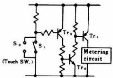
The switch (S₁) operates when touch switch (S₁₁) and shutter button are lightly pressed (about 0.5 mm).
Touch switch (S _11 ):
The periphery and the center of shutter button are electrodes. When it is touched, the resistance between the electrodes decreases ( several M ohms).
This is electrically detected Tr3,Tr6 , and then Tr_1 operate) and then power is supplied to the metering circuit.
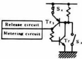
3. Voltage detecting circuit
If the power source voltage becomes lower than the specification during photography, Tr turns off and the release circuit stops working. The basic construction is as shown at left.
The B.C circuit is the same as this in principle of operation. It uses B.C indicating LED instead of release circuit.
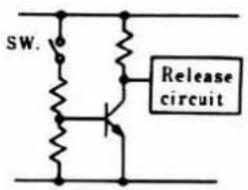
4. Metering operation circuit
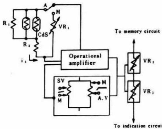
This circuit converts the change in brightness into the resistance of CdS, adds the aperture value and film sensitivity information, performs logarithmic compression, and puts out the signal to the indication circuit and memory circuit.
Auto Mode:
It consists of CdS and two resistors. Even if the resistance of CdS circuit changes (the brightness of the scene changes), the voltage applied to the circuit is kept constant by the operational amplifier, thus making the current (i_1) proportional to the brightness. The current (i_1) , SV and AV information from the resistors are treated by the operational as voltage corresponding to the exposure time. The voltage is applied to the memory circuit and indication circuit through the level shift circuit (including VR_2 , VR_3 ).
Manual Mode:
When the mode is shifted to Manual, CdS circuit is switched to standard resistor (VR _1 ) to make current (i) constant. Also, the brush of SV resistor is switched to that of TV resistor (resistor is used). Therefore, the output to the memory circuit varies in accordance with the position of the brush for TV resistor.
flowchart
graph TD
    A["Operational amplifier"] --> B["Resistors R1, R2, CDS"]
    A --> C["Inductor M"]
    A --> D["Capacitor M"]
    A --> E["Current i1"]
    A --> F["Current a.v."]
    G["To memory circuit"] --> H["Resistor VR1"]
    G --> I["Resistor VR2"]
    G --> J["Inductor M"]
    G --> K["Inductor M"]
    G --> L["Current a.v."]
    M["To indication circuit"] --> N["Resistor VR3"]
    M --> O["Resistor VR4"]
5. Indication circuit
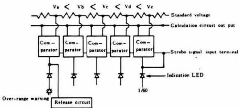
The indication circuit is a combination of comparators, which compares the output of calculation circuit and the standard voltage created in the indication circuit. When the values are close to each other, the corresponding LED is lighted. When the output of calculation circuit is between standard voltages intermediate range), two LED's are lighted.
The output of calculation circuit is compared with the standard voltage by comparators in the indication circuit (IC 2). When the values are close to each other, the corresponding LED is lighted. When the value is in an intermediate range, the outputs are given from two comparators to two LED's to turn them on at the same time.
When the over-range warning LED is lighted the over-range lock signal is given to the release circuit to lock the release. Also, when the signal for charge completion is emitted from exclusive strobo (8668), the comparator is turned off (LED OFF), then LED "60" is turned on end off by the signal.
flowchart
graph TD
    A["Over-range warning"] --> B["Release circuit"]
    B --> C["Com-parator"]
    C --> D["Com-parator"]
    D --> E["Com-parator"]
    E --> F["Com-parator"]
    F --> G["Strobe signal input terminal"]
    G --> H["Indication LED"]
    H --> I["1/60"]
    I --> J["Standard voltage"]
    J --> K["Calculation circuit out put"]
    style A fill:#f9f,stroke:#333
    style K fill:#ccf,stroke:#333
6. Magnetic release
With the contact piece attracted by the permanent magnet, the permanent magnet is temporarily demagnetized. Then the contact piece operates to release the mirror box. Condenser C_4 is charged through R_5 beforehand. When Tr_4 in operated by the release circuit, condenser C_4 serves to create a magnetic field, opposite to that of the permanent magnet, on the magnets provided around the permanent magnet. Then the permanent magnet is temporarily demagnetized thus releasing the contact piece.
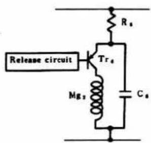
7. Over-rang lock
When release switch (S₂) is turned ON, C₃ is charged at a high speed, and the release circuit operates on completion of charge. In the case of over-range non-interlocking operation, C₃ is discharged not to operate the release circuit. When over-range LED is lighted in the indication circuit, Tr operates as well and C₃ is shortcircuited at both ends. Therefore, C₃ will not be discharged and the release circuit will not work.
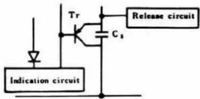
8. Memory circuit
This circuit stores the output of calculation circuit into condenser (C 1 ) through VR 2 and Tr switch.
The calculation circuit output (voltage corresponding to shutter speed) is charged into condenser (C_1) through VR, and Tr SW. But Tr SW. is turned OFF when Tr_4 is turned ON, and the calculation circuit is isolated from condenser (C_1) . Then the shutter speed is memorized.
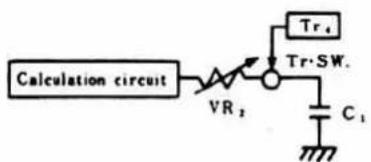
- Logarithmic expansion circuit
The memorized voltage cannot be used as it is because it has been logarithmically compressed. It must be changed to the original value. (This is called "logarithmic expansion".)
When the first curtain runs and trigger switch (S 1 ) turns off, Tr SW. is activated to operate Tr for expansion. The size of current (IC) flowing in Tr for expansion varies depending on the voltage charge in C 1 . When the charge voltage of C 1 is increased by 18 mV, the current is doubled (characteristic of Tr). Also, C 2 is charged by the current flowing in Tr for expansion, and when the charge voltage reaches a certain level, the control circuit operates causing the second curtain to run.
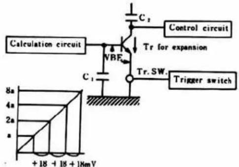
- Control circuit
In the logarithmic expansion circuit, condenser (C₂) for time constant is charged by the current subjected to logarithmic expansion. The shutter speed is controlled by the charge voltage. When C₂ has been charged up to a certain level, the comparator operates to turn off Tr. and then the shutter control magnet is turned OFF. Then the second curtain is released to start running.
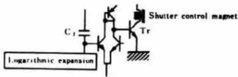
- Power source holding circuit
This circuit holds the power source until the end of shutter operation even when the release switch is turned off during operation of the camera.
When release switch (S₂) is turned ON, Tr operates to supply power to the release circuit and metering circuit, starting up each part. When release switch (S₂) is turned OFF, power source is held by the function of Tr, the same as with S₂ ON. With release completed, the set lever returns and circuit reset switch (S₄) is turned OFF, then the power holding circuit is also reset.
12. Bulb mode
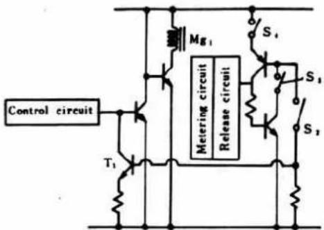
A bulb switch (S 1 ) is installed in the power source holding circuit. On turning off of the holding circuit, priority is given to "B" over the control circuit. And second curtain release is done by release switch (S 2 ).
When the shutter speed dial is set to "B", bulb switch (S 1 ) is turned OFF and the metering operation circuit is shifted to Manual. Next, when release switch (S 2 ) is turned ON, the voltage is detected to operate the release circuit, and the shutter opens. While release switch (S 2 ) is ON, T 1 operates and Mg 1 is ON (open). When release switch (S 2 ) turns off, power supply to the control circuit is cut off because the power source holding circuit is OFF. Then the shutter control magnet (Mg _1 ) turns off and the second curtain starts running.
13. Magnetic SELF
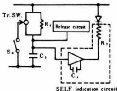
For ordinary photography, the release circuit is operated as C_s is charged (high speed). The circuit composition and the shutter speed have been changed in this self-timer.
When the mode selector switch is set to "Selftimer", the self switch (S 4 ) turns ON and Tr switch turns OFF. Next, when release switch (S 2 ) is turned on, C 3 is charged through C 4 . And the release circuit operates 8\~12 seconds later to activate the release magnet to operate the shutter. The indication LED blinks by the function of the SELF indication circuit consisting of C 4 and resistors in series. When the charge voltage of C 3 has reached a certain level, the composition of indication circuit changes causing the blinking intervals of LED to become faster.
14. Remote-control
In ordinary photography, metering switch (S₁ or S₁₁) turns ON and release switch (S₂) turns ON and then the shutter is operated. In remote control operation, the metering switch does not turn ON, therefore power is supplied to the metering circuit after release switch (S₂) is turned ON.
15. Winder control function
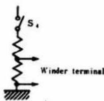
Unlike XD, XG is not furnished with a winder switch but provided with the signal from the reset switch (S _4 ) for the purpose of winder control. The winder operates when the winder terminal voltage is zero, and it stops when voltage exists.
The winder terminal voltage is 2V with S 4 ON, and 0V with the switch OFF. Also, S 4 is ON with winding completed, and OFF with shutter release completed.
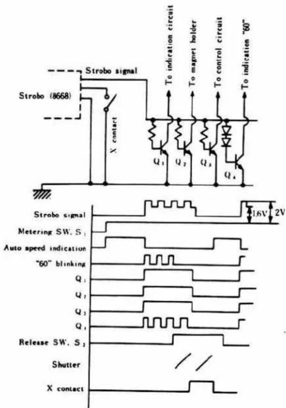
16. Strobo Auto
The circuit receives the signal of stobo (8668) and indicates for strobo charge completion in the finder and changes the shutter speed to the strobo-tuned speed.
When the charge of strobo has been completed, pulse signal enters the signal contact on the camera side from the signal contact on the strobo side. The pulse operates Q_1 Q_2 . Q_1 turns off the indication circuit. Q_2 holds the magnet, and Q_3 charge the condenser ( C_2 ) for time constant in the control circuit at a high speed (approx. 1/1000 sec.). Also, Q_4 operates at 2V and doesn't at 1.6V. Therefore, indication LED ("60") turns on and off.
When the shutter is operated and X contact is closed, the strobo flashes and the strobo signal goes out. Then Q: which held the magnet is turned off and the second curtain starts running, thus completing the exposure.
17. XG Time Chart
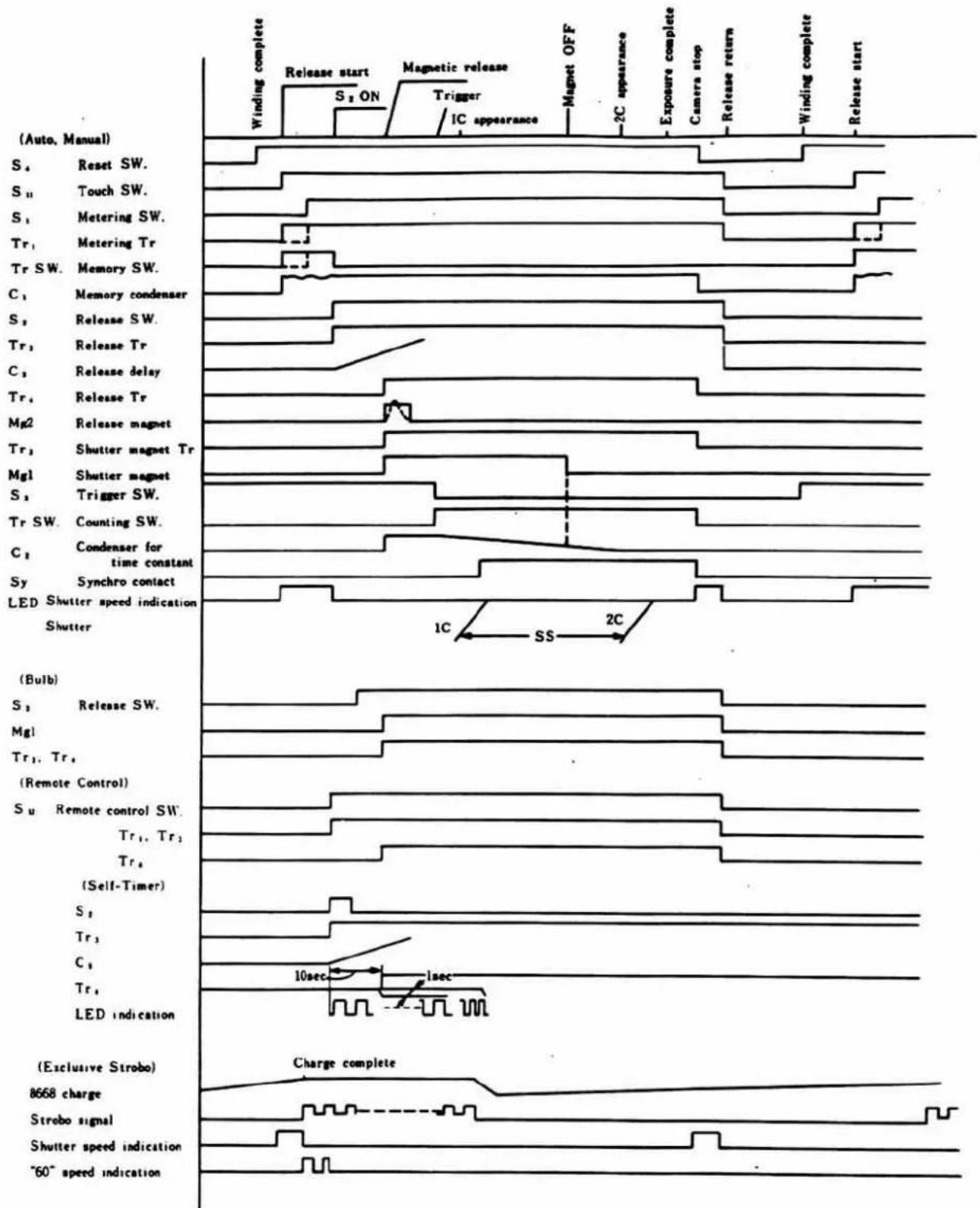
other
| Signal | Event Description | |--------|--------------------------------------| | S1 | Reset SW | | S2 | Touch SW | | S3 | Metering SW | | Tr1 | Metering Tr | | Tr2 | Memory SW | | C1 | Memory condenser | | S2 | Release SW | | Tr3 | Release Tr | | C3 | Release delay | | Tr4 | Release Tr | | Mg2 | Release magnet | | Tr3 | Shutter magnet Tr | | Mg1 | Shutter magnet | | S4 | Trigger SW | | Tr SW | Counting SW | | C5 | Condenser for time constant | | Sy | Synchro contact | | LED | Shutter speed indication | | Shutter| 1C, SS, 2C | | (Bulb) | Release SW | | Mg1 | (Remote Control) | | Su | Remote control SW | | Tr1 | Tr3 | | Tr4 | (Self-Timer) | | S1 | Tr3 | | C1 | Tr3 | | Tr4 | LED indication | | (Exclusive Strobo) | Charge complete | | 8668 charge | | | Strobo signal | | | Shutter speed indication | | | "60" speed indication | |D. Switch characteristics
| Mark | Name | Function | Operation | Before release | During exposure | After exposure |
| S1 | Metering switch | Turns on metering operation circuit to start metering, and indicates shutter sec. time in finder in AUTO mode. | Interlocked with shutter release shaft | (OFF) | (ON) | (OFF) |
| S2 | Release switch | Starts operating each circuit. | Interlocked with shutter release. | (OFF) | (ON) | (OFF) |
| S3 | Trigger switch | Starts time counting in Manual and Auto. | Turns OFF just after start of 1st curtain (Sutter block) | ON | OFF | ON |
| S4 | Reset switch | Prevention of misoperation during winding, circuit resetting, and winder control. | Turns ON on completion of winding.Winder operates at OFF. | ON | ON | OFF |
| S5 | Bulb switch | Circuit is shifted for Bulb. | Interlocked with speed dial.(OFF at Bulb) | |||
| S6.S7 | Mode switch | Interlocked with selftimer dial. | ||||
| B.C | Checks battery | |||||
| ON | Supplies power to metering switch. | |||||
| OFF | Cuts off power to circuit. | |||||
| SELF-TIMER | Circuit is shifted for self-timer. | |||||
| S8 | Auto-Manual switch | Circuit changeover for Auto & Manual. | CdS circuit OFF at Manual | |||
| S9 | TV (Speed) circuit ON at Manual. | |||||
| S10 | SV (ASA) circuit OFF at Manual. | |||||
| AV (Diaphragm) circuit at Manual. | ||||||
| S11 | Touch switch | Same as S1 | ON with shutter button touched. | |||
| Sy | Synchro switch | Strobe operation | Turns ON on completion of 1st curtain running, and OFF on completion of 2nd curtain running. | OFF | ON | OFF |
Circuit diagram
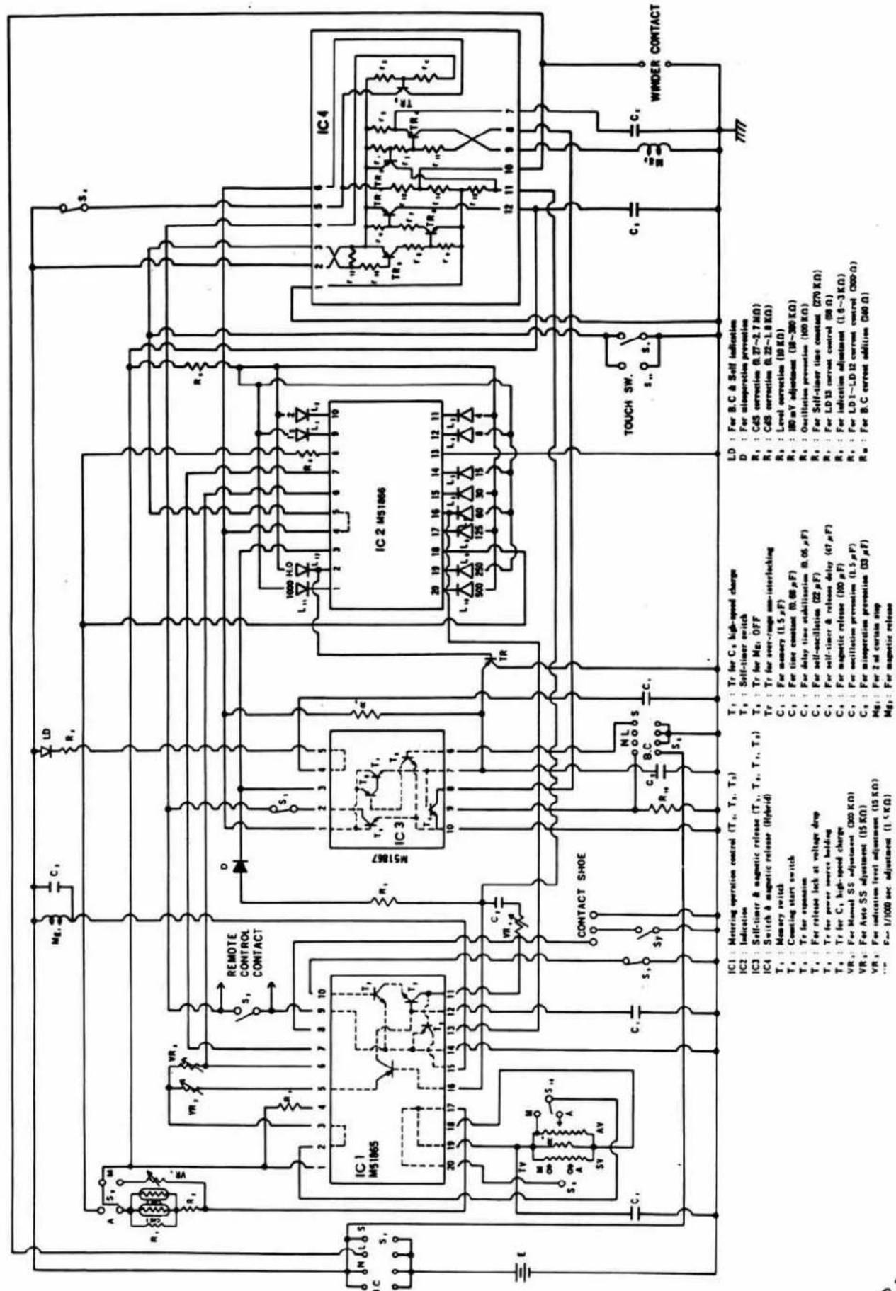
XG 7 (2006-100, -200) XG 2 (2006-300, -400) Parts List XG-E (2006-500, -600)
- This parts list, based upon the final model of 2006 series, includes ① parts modified or discontinued in the course of production and temporarily used, and their interchangeability; ② parts for models after 2006 series, which can also be used for 2006 series.
- Regarding those modified in the course of production, if they are interchangeable, only the new parts are mentioned.
- Part No. on the exploded view of the parts list is sometimes provided with ●, ○, or ※.
● : Modified in the course of production, and individually not interchangeable with previous type.
● : Discontinued in the course of production, newly added or temporarily used.
※ : Attached to screws or special screw numbers, showing the use for defective screw hole.
Regarding those provided with ● or Ⓞ, be sure to refer to the specified page. Also, do not remove the part from the dody to which the Ⓞ-marked part is attached.
Part No. Page Part No. Page
9431-1037-31----17 9535-6845-31----17
9431-1057-31----4 9563-4738-31----17
9431-1257-31----4
9431-1557-31----4
9431-3047-31----17
9431-3347-31----4
9431-3947-31----4
9431-4747-31----4
9431-5647-31----4
9431-6847-31----4
9431-8247-31----4
Variable resistor
9472-1529-38----17
9472-1539-38----17
9472-2049-38----17
Condenser
9531-1575-61----17
9531-2265-31----17
9531-3365-31----17
9531-4765-31----17
9534-1555-33----17
9534-1555-63----17
9535-1555-31----17
9535-1555-36----17
XG 7 CODE No. 2006-100, -200
XG 2 CODE No. 2006-300, -400
XG-E CODE No. 2006-500, -600
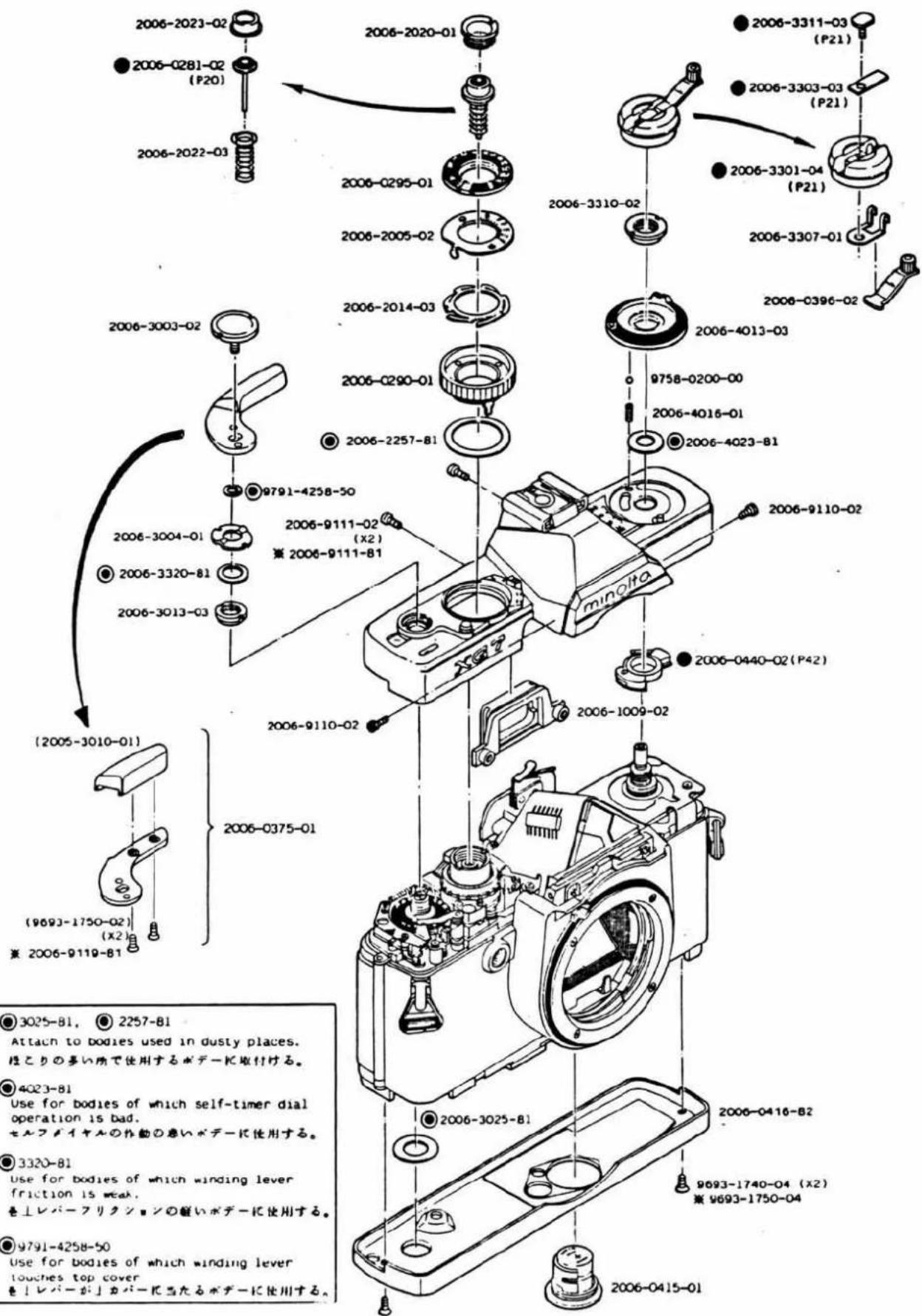
XG 2 CODE No. 2006-300, -400
XG-E CODE No. 2006-500, -600
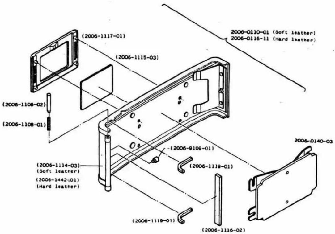
| Part No. | Part Name | Qty | |
| 2006-0110-01 | Back cover set | 裏蓋セット | 1 |
| (2006-1106-02) | Hinge axis A | ヒンジ軸A | 1 |
| (2006-1108-01) | Hinge spring | ヒンジスプリング | 1 |
| (2006-1114-03) | Back cover leather | 裏蓋貼皮 | 1 |
| (2006-1115-03) | Conversion scale | ASA,DIN換算板 | 1 |
| (2006-1116-02) | Back cover light shield plate | 裏蓋遮光片 | 1 |
| (2006-1117-01) | Back cover pocket | 裏蓋ポケット | 1 |
| (2006-1119-01) | Back cover light shield plate-B | 裏蓋遮光片-B | 2 |
| (2006-9109-01) | Hinge axis A screw | 裏蓋ヒンジ軸止めビス | 1 |
| 2006-0116-11 | Back cover set | 夾蓋セット | 1 |
| (2006-1442-01) | Back cover leather | 裏蓋貼皮 | 1 |
| 2006-0140-03 | Pressure plate set | 圧着板セット | 1 |
XG 7 CODE No. 2006-100, -200
XG 2 CODE No. 2006-300, -400
XG-E CODE No. 2006-500, -600
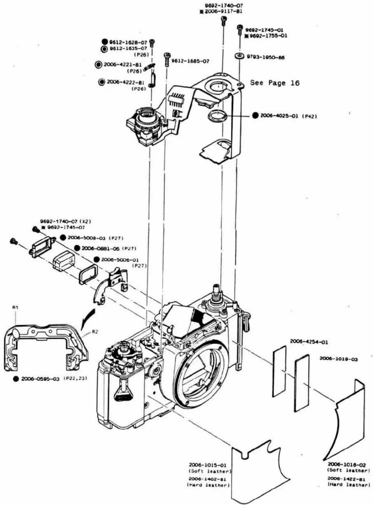
| Part No. | Part Name | Qty | |
| 2006-0595-03 | CdS circuit base plate set | CdS基板セット | 1 |
| 2006-0881-05 | Eye-piece lens set | 接眼レンズセット | 1 |
| 2006-1015-01 | Right side leather | 貼皮(右) | 1 |
| 2006-1016-02 | Left side leather | 貼皮(左) | 1 |
| 2006-1019-03 | Body leather | ポデー貼皮 | 1 |
| 2006-1402-81 | Right side leather | 貼皮(右) | 1 |
| 2006-1422-81 | Left side leather | 貼皮(左) | 1 |
| 2006-4025-01 | Contact receiver | セルフ切換接片ホルダー受け | 1 |
| 2006-4254-01 | Tape-A | フレキ接着テープ | 1 |
| 2006-5006-01 | Eye-piece lens light shield frame | 接眼レンズ遮光枠 | 1 |
| 2006-5008-03 | Eye-piece lens pressure | 接眼レンズ押え | 1 |
| 2006-9117-81 | Tapping screw | 0-1 | |
| 9612-1628-07 | Phillips type screw | 十字穴付なべ頭小ねじ | 1 |
| 9612-1685-07 | Phillips type screw | 十字穴付なべ頭小ねじ | 1 |
| 9692-1740-07 | Phillips type tapping screw | 十字穴付タッピンねじ | 3 |
| 9692-1745-01 | Phillips type tapping screw | 十字穴付タッピンねじ | 1 |
| 9692-1745-07 | Phillips type screw | 0-2 | |
| 9692-1755-01 | Phillips type screw | 0-1 | |
| 9793-1950-86 | Washer | 薄ワッシャー | 1 |
| 2006-4221-81 | SW.8 sub spring | SW.8 補助スプリング | 1 |
| 2006-4222-81 | Spring hanger | SW.8 補助スプリング掛け | 1 |
| Symbol | Part No. | Part Name | Type. | Qty. |
| R1 | 9431-3347-31 | Fixed resistor | 1/16W, 330K Ω | 1 |
| 9431-3947-31 | 1/16W, 390K Ω | |||
| 9431-4747-31 | 1/16W, 470K Ω | |||
| 9431-5647-31 | 1//6W, 570K Ω | |||
| 9431-6847-31 | 1/16W, 680K Ω | |||
| 9431-8247-31 | 1/16W, 820K Ω | |||
| 9431-1057-31 | 1/16W, 1M Ω | |||
| 9431-1257-31 | 1/16W, 1.2M Ω | |||
| 9431-1557-31 | 1/16W, 1.5M Ω | |||
| R2 | 9422-1516-32 | 1/8W, 150 Ω | 1 | |
| 9422-2216-32 | 1/8W, 220 Ω | |||
| 9422-2716-32 | 1/8W, 270 Ω | |||
| 9422-3316-32 | 1/8W, 330 Ω | |||
| 9422-3916-32 | 1/8W, 390 Ω | |||
| 9422-4716-32 | 1/8W, 470 Ω | |||
| 9422-5616-32 | 1/8W, 560 Ω | |||
| 9422-6816-32 | 1/8W, 680 Ω | |||
| 9422-8216-32 | 1/8W, 820 Ω | |||
| 9422-1026-32 | 1/8W, 1K Ω | |||
| 9422-1226-32 | 1/8W, 1.2K Ω | |||
| 9422-1526-32 | 1/8W, 1.5K Ω | |||
| 9422-1826-32 | 1/8W, 1.8K Ω |
XG 7 CODE No. 2006-100, -200
XG 2 CODE No. 2006-300, -400
XG-E CODE No. 2006-500, -600
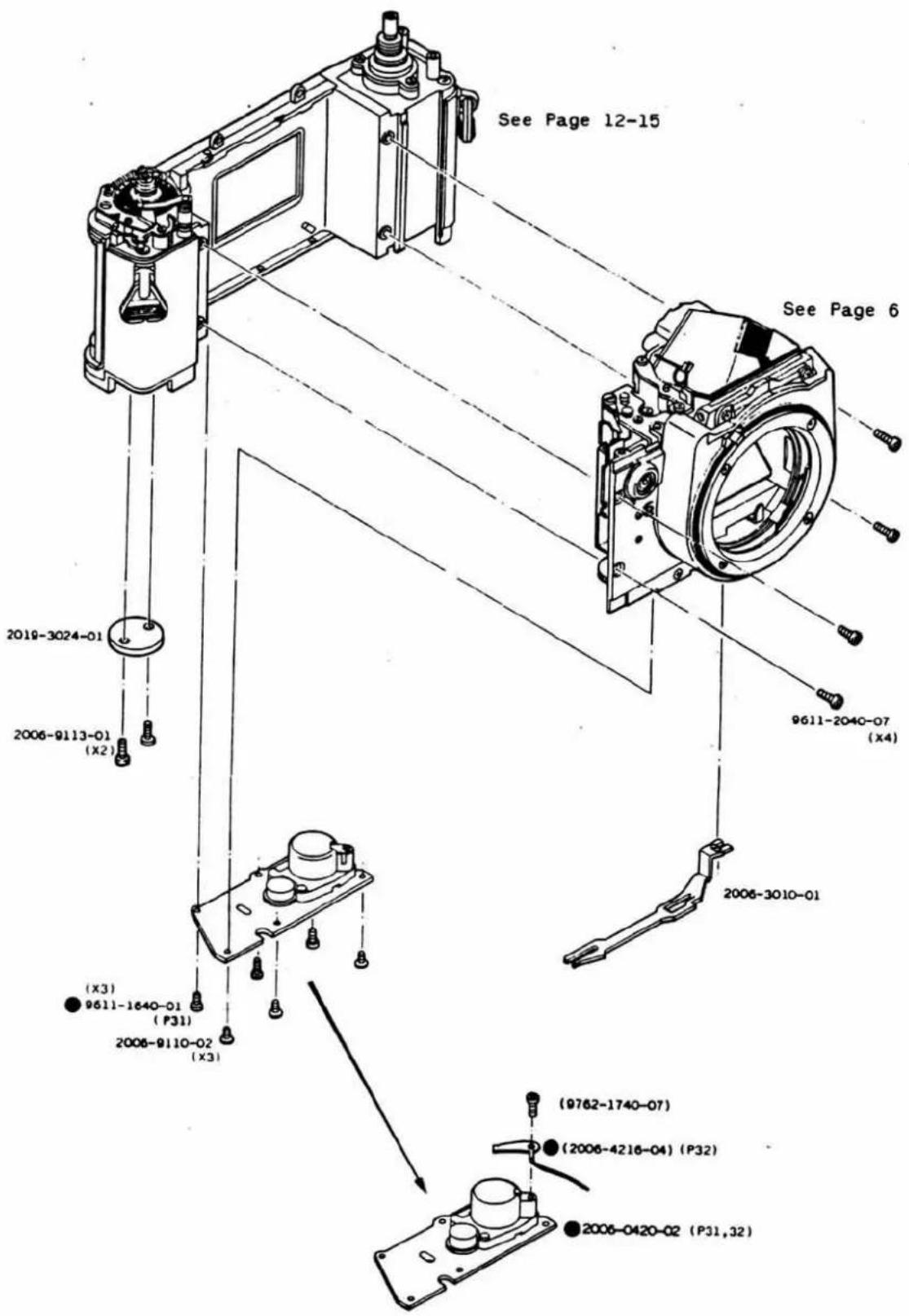
XG 2 CODE No. 2006-300,-400
XG-E CODE No. 2006-500,-600
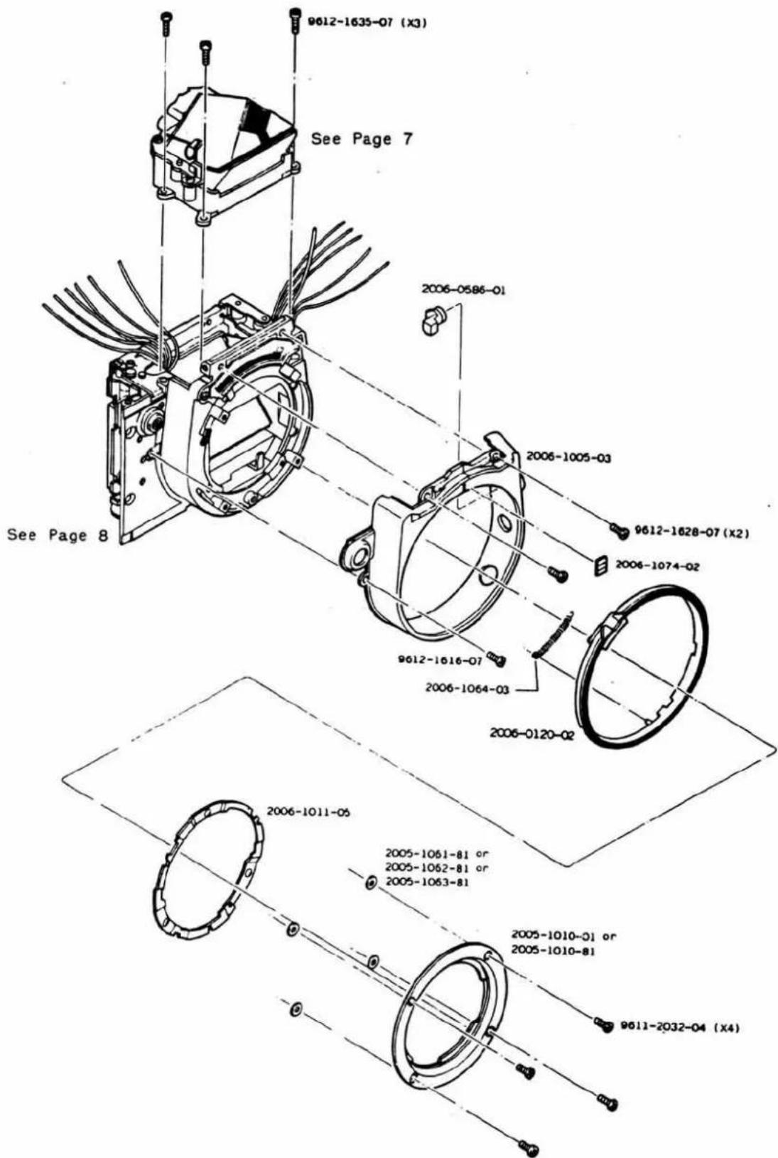
| Part No. | Part Name | Qty | |
| 2006-0120-02 | Aperture coupling ring set | 連結リングセット | 1 |
| 2006-0586-01 | Lens lock button set | レンズロック卸セット | 1 |
| 2006-1005-03 | Front cover | 前カバー | 1 |
| 2005-1010-01 | Bayonet lens mount | パヨネット座板 | 1 |
| 2005-1010-81 | Bayonet lens mount (-0.1mm) | パヨネット座板(-0.1mm) | |
| 2006-1011-05 | Bayonet spring | パヨネットスプリング | 1 |
| 2005-1061-81 | Adjustment washer-A t=0.02 | 座板調整用ワッシャーA | Some若 |
| 2005-1062-82 | Adjustment washer-B t=0.05 | 座板調整用ワッシャーB | Some若 |
| 2005-1063-81 | Adjustment washer-C t=0.1 | 座板調整用ワッシャーC | Some若 |
| 2006-1064-03 | Aperture coupling ring spring | 連結リングスプリング | 1 |
| 2006-1074-02 | Front cover indication | 前カバー指標 | 1 |
| 9611-2032-04 | Phillips type screw | 十字穴付なべ頭小ねじ | 4 |
| 9612-1616-07 | Phillips type screw | 十字穴付なべ頭小ねじ | 1 |
| 9612-1628-07 | Phillips type screw | 十字穴付なべ頭小ねじ | 2 |
| 9612-1635-07 | Phillips type screw | 十字穴付なべ頭小ねじ | 3 |
7-1
XG 7 CODE No. 2006-100, -200
XG 2 CODE No. 2006-300,-400
XG-E CODE No. 2006-500,-600
![[New type].... type fresnel len 2006-5016-03 (X2) 2006-5017-04 2006-5039-01 (X2) 2006-5803-02 ( X3 ) 9692-1740-07 第 2006-9117-81 2006-5015-02 9622-1630-01 (X3) 9693-1740-07 第 9695-1750-01 2006-5014-03 (P30) 2006-5018-01 (2006-5007-04) (P28) (2006-5809-02) 2006-0592-01 (2006-5005-04) (P29) 2006-5024-01 (P30) 2006-5011-02 (P28) 2006-5013-03 (P28) 2006-0509-01 (P30) ( X3 ) 2006-5013-03 (P28) 2006-0504-01 (P27, 28, 30) 2006-5805-06 (P28) (2006-5032-01) (2006-5031-01 (P30)](/content/2026/05/999025/images/898b2dae1a94846a8257899bb990761b2741b2daca6efd4cdf8576327b0a2fde.jpg)
7-1
| Part No. | Part Name | Qty | |
| 2006-0504-01(2006-5032-01) | Penta. holder set | ペンタホルダーセット | 1 |
| Packing-B | 防塵モルトブレンB | 1 | |
| 2006-0509-01 | Fresnel lens holder set | 焦点板ホルダーセット | 1 |
| 2006-0592-01 | Penta. receiver set | ペンタ受けセット | 1 |
| (2006-5005-04) | Penta. receiver | ペンタ受け | 1 |
| (2006-5007-04) | Scale plate | 目盛板 | 1 |
| (2006-5809-02) | L.E.D mirror | 光路棒 | 1 |
| 2006-5011-02 | Fresnel lens pressure spring | 焦点板押えスプリング | 1 |
| 2006-5013-03 | Fresnel lens holder spring | 焦点板ホルダースプリング | 3 |
| 2006-5014-03 | Penta. pressure (Left side) | ペンタ押え板(左) | 1 |
| 2006-5015-02 | Penta. pressure (Right side) | ペンタ押え板(右) | 1 |
| 2006-5016-03 | Penta. spring | ペンタ押えスプリング | 2 |
| 2006-5017-04 | Penta. pressure | ペンタ押え板 | 1 |
| 2006-5018-01 | L.E.D diffusion plate | LED 扡散板 | 1 |
| 2006-5024-01 | Packing-C | 防塵モルトブレンC | 1 |
| 2006-5031-01 | Packing-A | 防塵モルトブレンA | 1 |
| 2006-5039-01 | Penta. pressure tape | ペンタ押え板接着テープ | 2 |
| 2006-5803-02 | Penta. prism | ペンタブリズム | 1 |
| 2006-5805-06 | Fresnel lens | 焦点板 | 1 |
| 2006-9117-81 | Tapping screw | 0-3 | |
| 9622-1630-01 | Screw | とがり先止めねじ | 3 |
| 9692-1740-07 | Phillips type tapping screw | 十字穴付タッピンねじ | 3 |
| 9693-1740-07 | Phillips type tapping screw | 十字穴付タッピンねじ | 1 |
| 9693-1750-04 | Phillips type screw | 0-1 |
7-2
XG 7 CODE No. 2006-100, -200
XG 2 CODE No. 2006-300, -400
XG-E CODE No. 2006-500, -600
[Previous type]..... ☑ type fresnel lens
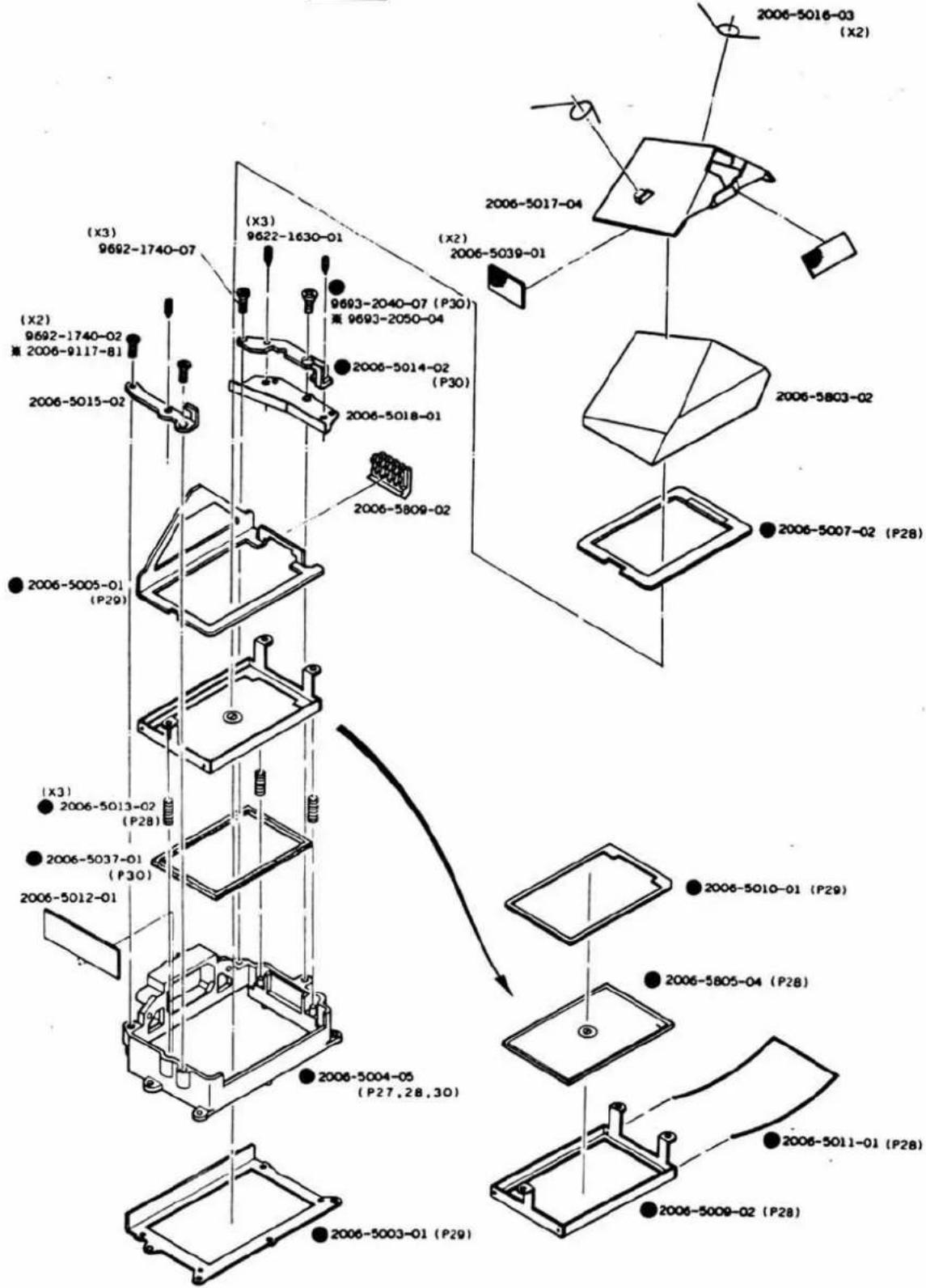
7-2
| Part No. | Part Name | Qty | |
| 2006-5003-01 | Penta. holder shield plate | ペンタホルダー防塵板 | 1 |
| 2006-5004-05 | Penta. hodler | ペンタホルダー | 1 |
| 2006-5005-01 | Penta. receiver | ペンタ受け | 1 |
| 2006-5007-02 | Scale plate | 目盛板 | 1 |
| 2006-5009-02 | Fresnel lens holder | 焦点板ホルダー | 1 |
| 2006-5010-01 | Fresnel lens frame | 視野枠 | 1 |
| 2006-5011-01 | Fresnel lens pressure spring | 焦点板押えスプリング | 1 |
| 2006-5012-01 | Space prevention plate | ペンタガタ防止片 | 1 |
| 2006-5013-02 | Fresnel lens holder spring | 焦点板ホルダースプリング | 3 |
| 2006-5014-02 | Penta. pressure (Left side) | ペンタ押え板(左) | 1 |
| 2006-5015-02 | Penta. pressure (Right side) | ペンタ押え板(右) | 1 |
| 2006-5016-03 | Penta. spring | ペンタ押えスプリング | 2 |
| 2006-5017-04 | Penta. pressure | ペンタ押え板 | 1 |
| 2006-5018-01 | L.E.D diffusion plate | LED拡散板 | 1 |
| 2006-5037-01 | Finder packing | フアインダー防塵片 | 1 |
| 2006-5039-01 | Penta. pressure tape | ペンタ押え板接着テープ | 2 |
| 2006-5803-02 | Penta. prism | ペンタブリズム | 1 |
| 2006-5805-04 | Fresnel lens | 焦点板 | 1 |
| 2006-5809-02 | L.E.D mirror | 光路棒 | 1 |
| 2006-9117-81 | Tapping screw | 0-3 | |
| 9622-1630-01 | Screw | とがり先止めねじ | 3 |
| 9692-1740-02 | Phillips type tapping screw | 十字穴付タッピンねじ | 2 |
| 9692-1740-07 | Phillips type tapping screw | 十字穴付タッピンねじ | 1 |
| 9693-2040-07 | Phillips type tapping screw | 十字穴付タッピンねじ | 1 |
| 9693-2050-04 | Phillips type screw | 0-1 |
XG 7 CODE No. 2006-100, -200
XG 2 CODE No. 2006-300, -400
XG-E CODE No. 2006-500, -600
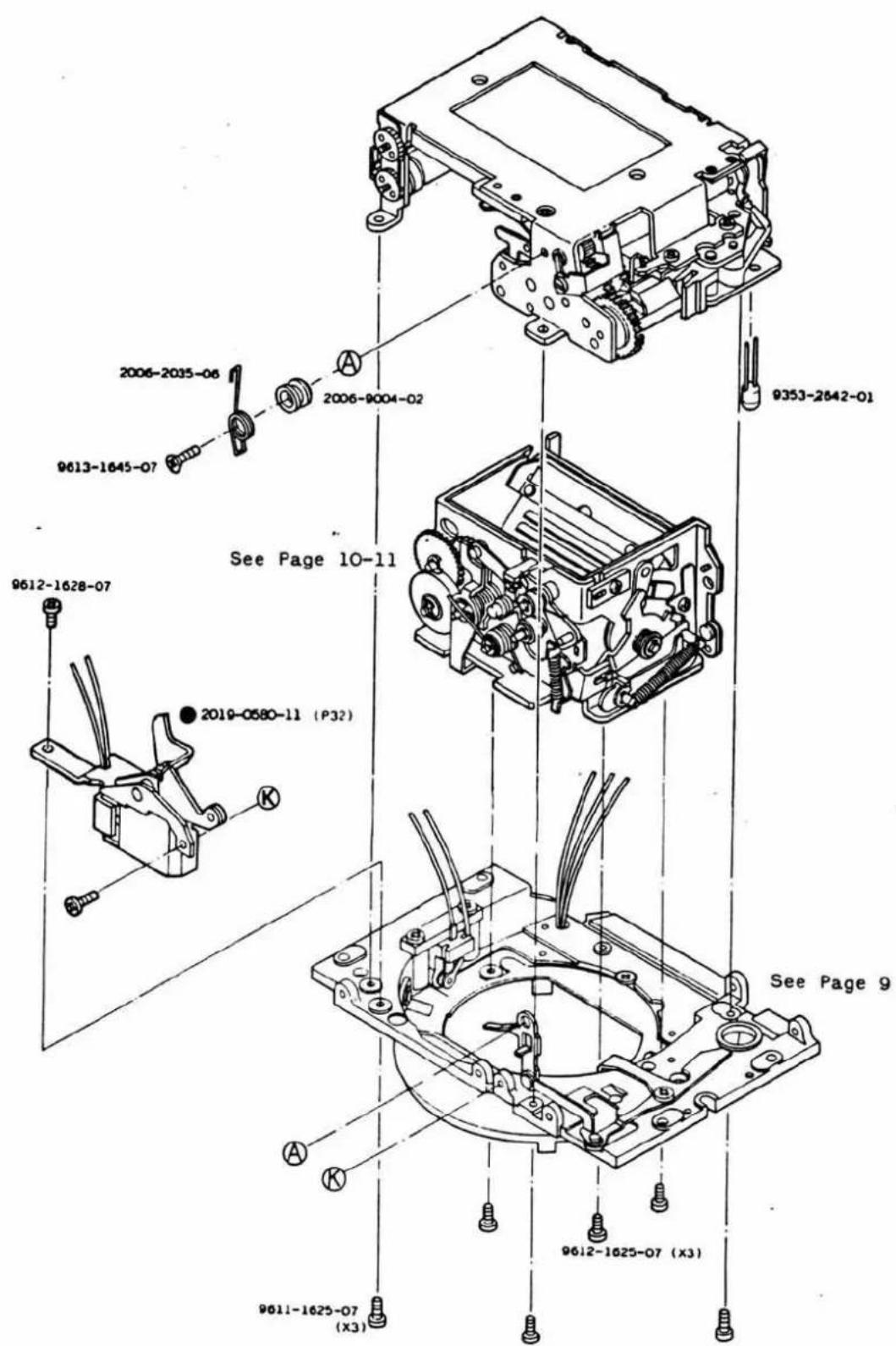
8
| Part No. | Part Name | Qty | |
| 2019-0580-11 | MG 2 set | MG 2セット | 1 |
| 2006-2035-06 | Release operation lever spring | 敷着用スプリング | 1 |
| 2006-9004-02 | Release operation lever A set screw | レリーズ連結レバーA止めビス | 1 |
| 9353-2642-01 | L.E.D | L.E.D | 1 |
| 9611-1625-07 | Phillips type screw | 十字穴付なべ頭小ねじ | 3 |
| 9612-1625-07 | Phillips type screw | 十字穴付なべ頭小ねじ | 3 |
| 9612-1628-07 | Phillips type screw | 十字穴付なべ頭小ねじ | 2 |
| 9613-1645-07 | Phillips type screw | 十字穴付皿小ねじ | 1 |

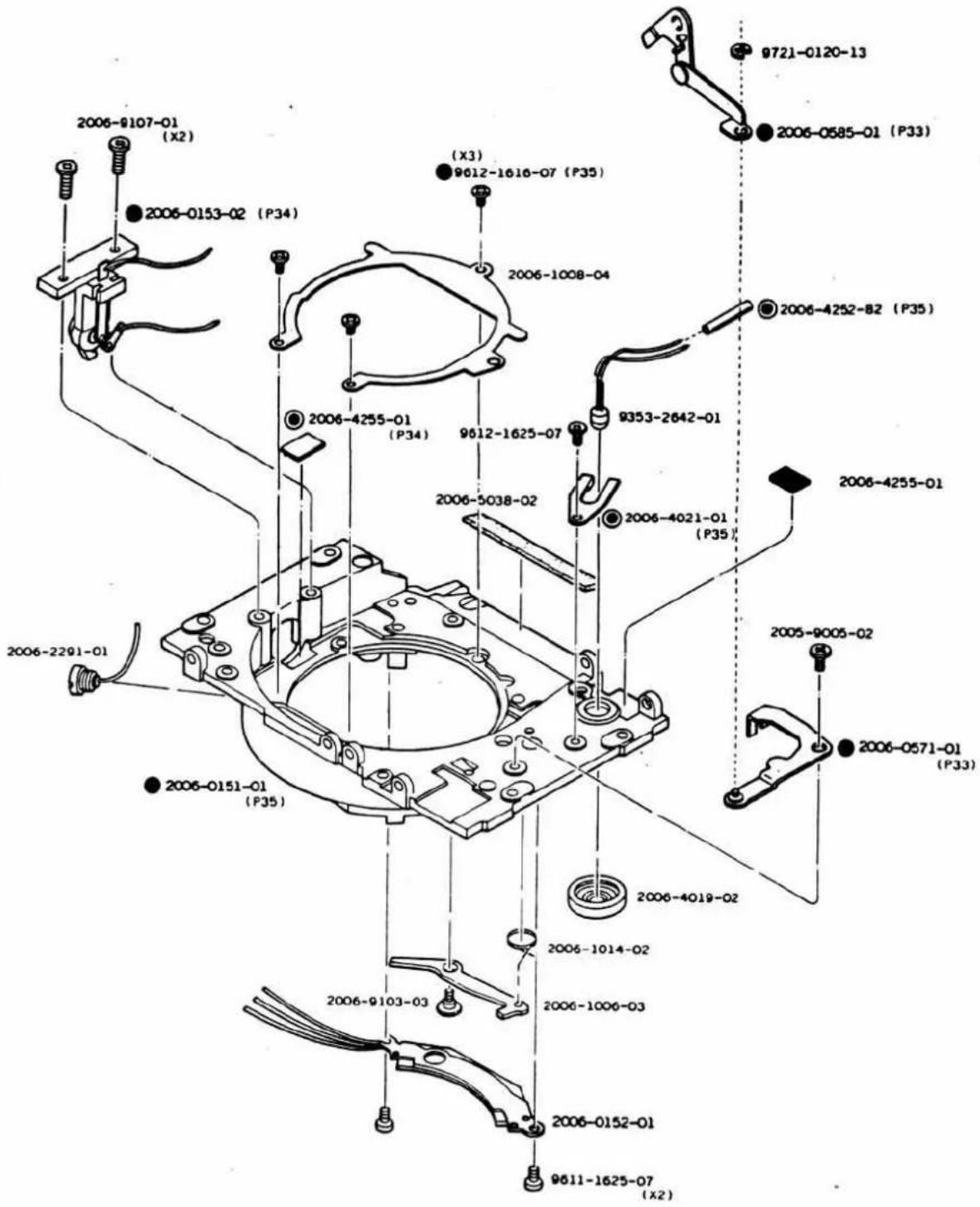
9-1
XG 2 CODE No. 2006-300, -400
XG-E CODE No. 2006-500, -600
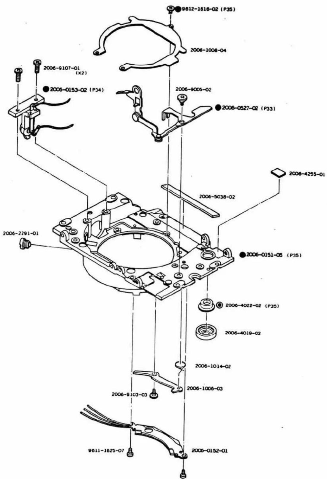
9-2
Part No. Part Name Qty
XG 2 CODE No. 2006-300, -400
XG-E CODE No. 2006-500, -600
XG 2 CODE No. 2006-300, -400
XG-E CODE No. 2006-500, -600
Assy. Part No.
2006-0402-03
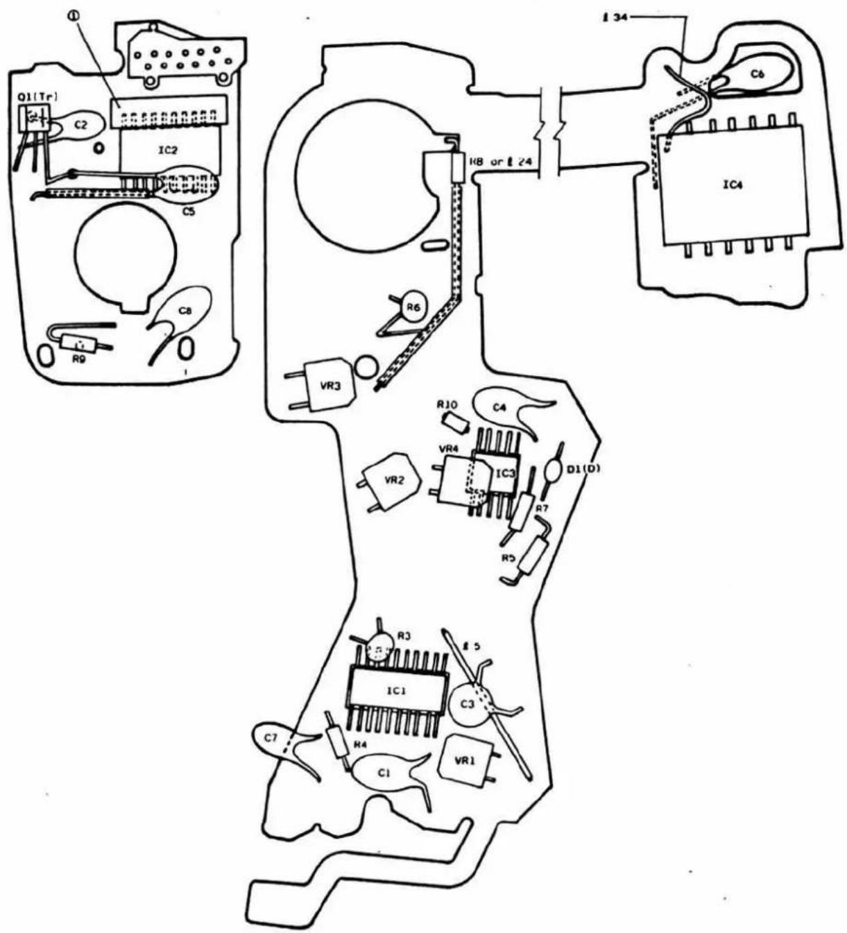
Assy Part No. 2006-0402-03
Assy Part Name Flexible circuit base plate set
フレキシブル基板セット
| Symbol | Part No. | Com | Part Name | Type. | Qty |
| IC1 | 2006-4301-03 | I C | M51865 | 1 | |
| IC2 | 2006-4302-03 | M51866 | 1 | ||
| IC3 | 2006-4303-03 | M51867 | 1 | ||
| IC4 | 2006-4304-07 | HIC | 1 | ||
| D1(D) | 9361-5631-01 | Diode | KB162 | 1 | |
| Q1(Tr) | 9363-1032-01 | ^oz_03 | Transistor | 2SA1162 | 1 |
| R3 | 9431-1037-31 | Fixed resistor | 1/16W 10KΩ | 1 | |
| R5 | 9422-1046-32 | 1/8W 100KΩ | 1 | ||
| R6 | 9431-3047-31 | 1/16W 300KΩ | 1 | ||
| R7 | 9422-6806-32 | 1/8W 68Ω | 1 | ||
| R8 | 9422-3916-32 | 1/8W 390Ω | 1 | ||
| 9422-8216-32 | 1/8W 820Ω | ||||
| 9422-1826-32 | 1/8W 1.8KΩ | ||||
| 9422-3326-32 | 1/8W 3.3KΩ | ||||
| L24 | 2006-8408-01 | Lead wire Pink | 60.08/7 wries B=35mm | ||
| R9 | 9422-3016-62 | Fixed resistor | 1/8W 300Ω | 1 | |
| R10 | 9422-2416-62 | 1/8W 240Ω | 2 | ||
| VR1 | 9472-2049-38 | Variable resistor | VG062K 200KΩ | 1 | |
| VR3 VR2 | 9472-1539-38 | VG062K 15KΩ | 2 | ||
| VR4 | 9472-1529-38 | VG062K 1.5KΩ | 1 | ||
| C1 | 9535-1555-36 | Condenser | 1.5μF/35V | 1 | |
| C2 | 9535-6845-31 | 0.68μF/35V | 1 | ||
| C3 | 9563-4738-31 | 0.047μF/1.2V | 1 | ||
| C4 | 9531-2265-31 | 22μF/3.15V | 1 | ||
| C5 | 9531-4765-31 | 47μF/3.15V | 1 | ||
| C6 | 9531-1575-61 | 150μF/3.15V | 1 | ||
| C7 | 9534-1555-33 | or | 1.5μF/25V | 1 | |
| 9534-1555-63 | or | 1.5μF/20V | |||
| 9535-1555-31 | 1.5μF/35V | ||||
| C8 | 9531-3365-31 | 33μF/3.15V | 1 | ||
| L5 | 2006-8403-01 | Lead wire Blue | φ0.08/7 wiresf=27mm | 1 | |
| L34 | 2006-8403-01 | Blue | 60.08/7 wiresf=20mm | 1 | |
| 1 | 2006-4260-01 | Isolation tape-A 色绿层 A | t=0.1 15×4.5mm | 1 | |
※ 1. When HIC (2006-4304-02) with no lead wire § 34 is replaced with a type after -03, the soldering position of §34 should be different. (Refer to P.46 - 48.)
※ 2. Since the shutter block is grounded to ⊙ of power supply, X earth plate (2204) and lead wire 20 are not needed and have discontinued. (Allowable to remove.)
※ 3. New type of 2019-0580 has been modified so that it can be grounded to of power supply from magnet base plate. So, earth wire (Black) has been discontinued.
※ 4. Shutter block is grounded to ⊙ power supply the same as in *2. So, §14 is not needed and has been discontinued. (Allowable to remove.)
※ 5. For bodies of which (inclined) indication cannot be adjusted by R8, lead wire ( 24) is used instead of R8.
- In bodies at the initial stage of massproduction, the positions of §2 and §19-2 are opposite to those in this wiring diagram. (If AM switch is in normal conditions, there is no problem of positions.)
※ 7. In the case of Black body, the top cover cannot be grounded to ⊙ of power supply. Therefore, CdS circuit base plate (2006-0596) with earth contact and lead wire (23 are required. (For discontinuance of contact, refer to P.25)
The details of modifications of parts provided with ● or ● in pages 1 through 19 are explained in the following.
- They are classified into Types A\~B or Types A\~D according to the frequency of modifications, and the differences are mentioned in tables.
- The parts are interchangeable with other types only when they come in a set with the relative parts of each type.
- When there are relative parts to be modified, the part cannot be individually modified to other type. The relative parts must also be modified to make set part.
- For parts of previous type which cannot be supplied, (×) is attached to the tail of the part number in the table. If it is necessary to modify the (×)-marked part, replace it with other type.
- Do not use Type A for bodies with Type B attached. (It may cause shortcircuit.)
Top cover set for XG-E XG-E川上カバーセノト
CdS circuit base plate set CdS基板七卜
When replacing the top cover set Types A\~C of P. 22 with Type D (or replacing only the relative parts of contact with Type D), it is necessary to modify the way of finishing (replacing) or CdS P.C. board set mentioned below and the lead wiring method.
- Drill the fastening pins of CdS P.C. board set and remove the contact. Also, cut off the part above the dotted line by nippers. (It is also allowable to replace it to Type D (2006-0596-02)).
- Replace the lead wire _21 (white) and _22 (green) with those 25\~30 mm longer. • In the case of black body, replace _23 (black) with a longer one as well.
- Connect each lead wire.
各リード線を配線する。
AM change holder set
AM 切換ホルダーセット
2006-2012
AM change spring
AM 切換スプリング
2006-4221
SW. 8 sub spring
SW. 8補助スプリング
2006-4222
Spring hanger
SW. 8補助スプリング掛け
8. Penta holder 1 (related to eyepiece modification)
9. Penta holder 2 (related with fresnel modification)
ペンタホルダー2(焦点板変更の関連)
- Note that 2006-5004 and 0504 are related with parts other than those mentioned on this page. (Refer to P.27 and 30.)
● 2006-0503 is also related with other parts. (Refer to P. 36.) - 2006-5004, 0504はこのページ以外の部品との関連もありますので注意して下さい。(P.27, P.30参照)
- 2006-0503も他の部品との関連があります。(P.36参照)
| Type A, B, B' | Type C |
2006-5004-03 or2006-5004-04 or2006-5004-05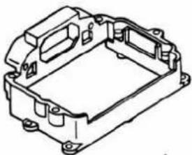 | 2006-0504-01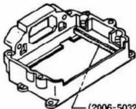 Addition(2006-002-01)···新設 Addition(2006-002-01)···新設 |
2006-5805-04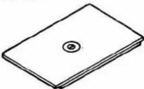 | 2006-5805-06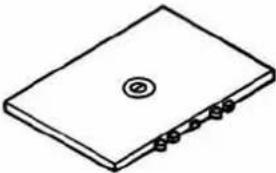 |
2006-5008-02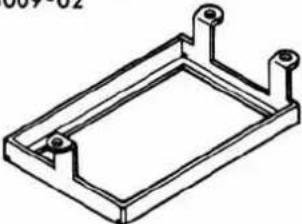 | 2006-0509-01 |
2006-5011-01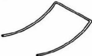 | 2006-5011-02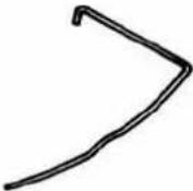 |
2006-5007-02 | 2006-5007-01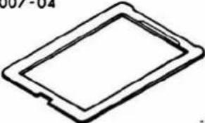 |
2006-5013-02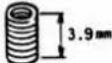 | 2006-5013-03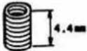 |
Continued to next page.
次ページに続く
| Type A, B, B' | Type C |
2006-5005-01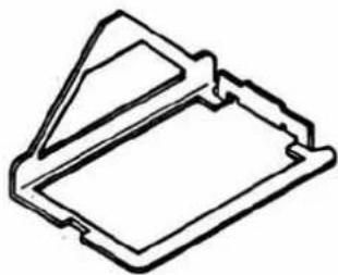 | 2006-5005-04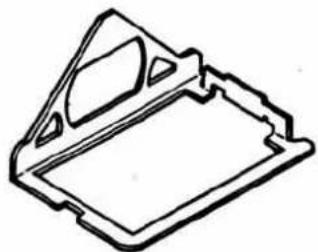 |
| ● Type C can be used.Type C使用可能 | |
2006-0503-01 or2006-05" 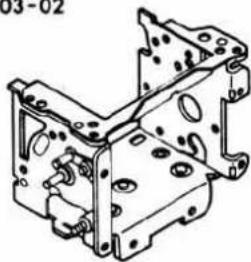 | 2006-0503-03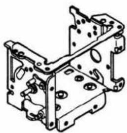 |
2006-5003-01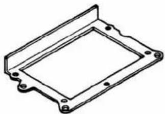 | Not used.使用しない |
2006-5010-01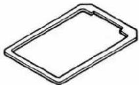 | Not used.使用しない |
10. Penta holder 3 (related with penta. pressure modification)
- Battery case base plate 1 (For Type C, refer to next page.)
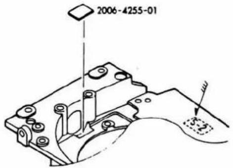
- When Type B is combined with front base plate of which the arrow-marked part number begins with 1\~5, 2006-4255 is required.
- 下図矢印部の最初の数字が1~5の前枠とType Bを組合わせる場合は2006-4255が必要です。
2006-0153
2006-0154
2006-4227
2006-4228
2006-4230
2006-4241
2006-4255
| Type A | Type B | Type C |
2006-0151-01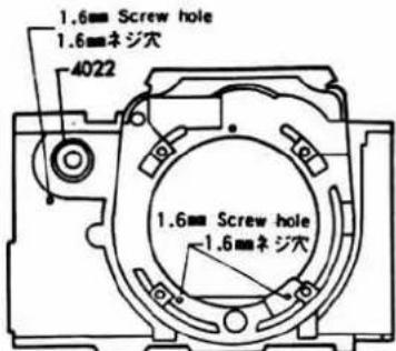 | 2006-0151-02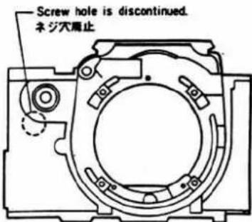 | 2006-0151-05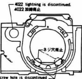 |
2006-4252-819612-1616-07 (ScLED(Can be change to t(Type Bに変更可能) 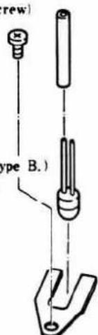 2006-4021-01 2006-4021-01 | 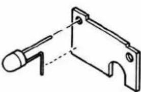 | Same as Type B.Type Bと同じ |
| (Tightened to 0151.)(0151に加稀) | (Tightened to 0151.)(0151に加稀) | 2006-4022-02 |
9612-1616-07 (Screw × 3)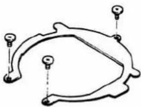 | Same as type A.Type Aと同じ | 9612-1616-07 (Screw × 1)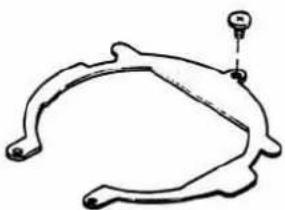 |
① Replace 5112 and 5114 with Type C.
② Stick 5120-81. (Confirm the returning of mirror when shutter releases at the "B" setting with the body upside-down, after bond the mirror arm cushion on the mirror holder arm.)
③ Replace 5042 (see next section) with Type B.
④ Replace 5042 and 0523 (see next section) with Type C.
- Types B and C are used for the adjustment of bodies of which the operation timing of winding claw and winding stop lever is not in correct order as shown below. [Correct timing when winding lever is slowly returned from the position of complete winding]
- Type B, Cは巻取爪と巻止めレバーの作動タイミングが、下図の順序になっていないボデーの調整用です。 [巻上げ完了状態から巻上げレバーをゆっくりと戻した時の正規タイミング]
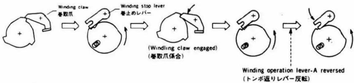
flowchart
graph LR
    A["Claw"] --> B["Winding claw 巻取爪"]
    B --> C["Winding stop lever 巻止のレバー"]
    C --> D["(Windling claw engaged) (巻取爪係合)"]
    D --> E["Winding operation lever-A reversed (トンボ返りレバー反転)"]
    E --> F["End"]
| Type A | Type B | Type C |
| 2006-3012-01 | 2006-3012-81 | 2006-3012-85 |
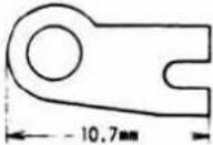 | 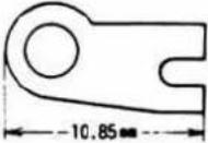 |  |
- With R_11 and C_16 of next section 3 added to IC_4 of Type B, the performance is the same as Types E and F.
- Type BのIC₄に次項3のR₁₁, C₁₀を追加すればType E, Fと同性能になります。
| Type A | Type B | Type C |
| 2006-4304-02 (×) | 2006-4304-03 (×) | 2006-4304-04 (×) |
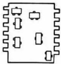 | 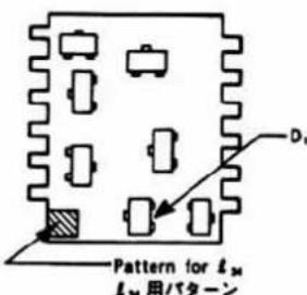 ● D_1 is added.● D_1 追加 ● D_1 is added.● D_1 追加 | 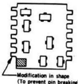 形状変更(ピン折れ対策) 形状変更(ピン折れ対策) |
| Type D | Type E | Type F |
| 2006-4304-05 (×) | 2006-4304-06 (×) | 2006-4304-07 |
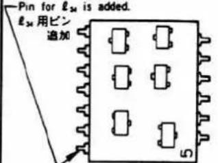 | 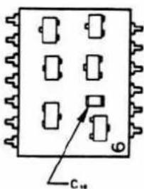 | 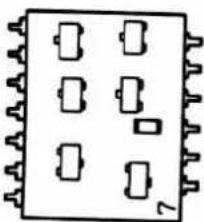 |
| ● D_1 is discontinued, and circuit is modified.●Pin is modified to metallic pin.● D_1 廃止.回路変更●ピンを金属ピンに変更 | ● C_10 is added.● C_10 追加 | ●Pattern is modified.●パターン変更 |
If the faulty operation of camera as mentioned below takes place, take one of the following measures. ① Fit the repair part. ② Replace IC₄ (4304). ③ Replace flexible circuit base plate set.
| Faulty operation | Measures parts | Part No. taken measures | |
| IC4 | Flexible circuit base plate set | ||
| ●Depressing shutter button with mode switch OFF, shutter is not released when mode switch is turned ON. | — | _34 (Fig. 1), 4304-03 | 0402-02 |
| ●It is unable to release self-timer operation.●Self-timer starts when mode switch is shifted to SELF after depressing shutter button with mode switch OFF. | C9(Fig. 2) | — | 0402-02(LED board is modified in pattern.) |
| When contact failure with S7;●Winder operates when mode switch is moved.●Self-timer starts when mode switch is shifted from OFF to SELF. | R11(Fig. 3) | 4304-05(Circuit is modified.) | 0402-03 |
| ●Self-timer starts when a flash of high trigger voltage is flashed to test. | C10(Fig. 2) | 4305-06(C10is built in.) | 0402-03 |
(Refer to next page for Figs. 1\~3.)
Note: Avoid overlapping of different measures. (For example, fitting R_11 to IC_4 of -05. All measures have been taken in -07 for IC_4 supplied for servicing at present.)
: To fit C_10 results in completion of the measure to be taken for C_9 .
: When replacing IC4 of -02 with IC4 of the flexible circuit base plate set after -03, it is necessary to use lead wire _34 .
③各種対策について
Fitting of R_11 R_11 の取付け
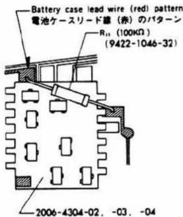
- Winding base plate-B / 卷取台板B
| Type A | Type B | Type C | Reference page |
2006-0384-01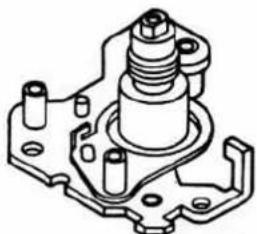 | 2006-0384-81 (x)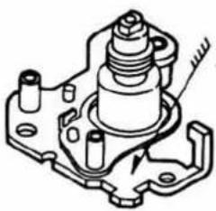 | 2006-0384-02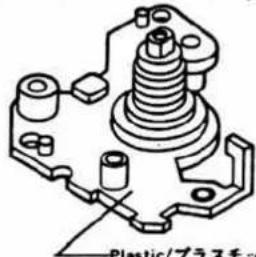 | |
Body (No supply / 非供給)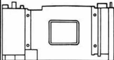 | Body (No supply / 非供給)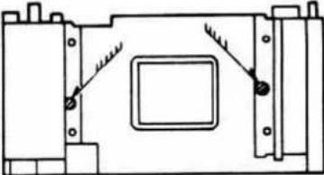 | Body (No supply / 非供給)(Type B) | |
2006-0151-02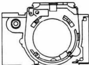 ● Type B can be used.● Type B使用可能 ● Type B can be used.● Type B使用可能 | 2006-0151-05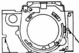 | 2006-0151-05(Type B) | P. 41 |
2006-0338-01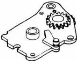 | 2006-0338-02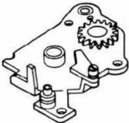 | 2006-0338-02(Type B) | |
2006-0340-01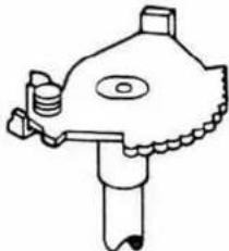 | 2006-0340-02 or2019-0340-12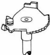 | 2006-0340-02 or2019-0340-12(Type B) | P. 46 |
Disassembly, Assembly and Adjustment
For disassembly, refer to the related pages in the reverse order as the contents of this manual are arranged in the order of procedures for assembling and adjusting.
- Abbreviations—
+: Assembly note and reference.
G : Grease to be used and where to apply it.
☐ : Oil to be used and where to apply it.
B : Bond to be used and where to bind.
T: Special tool No. and where to use it.
■ Disassembling Procedures Chart
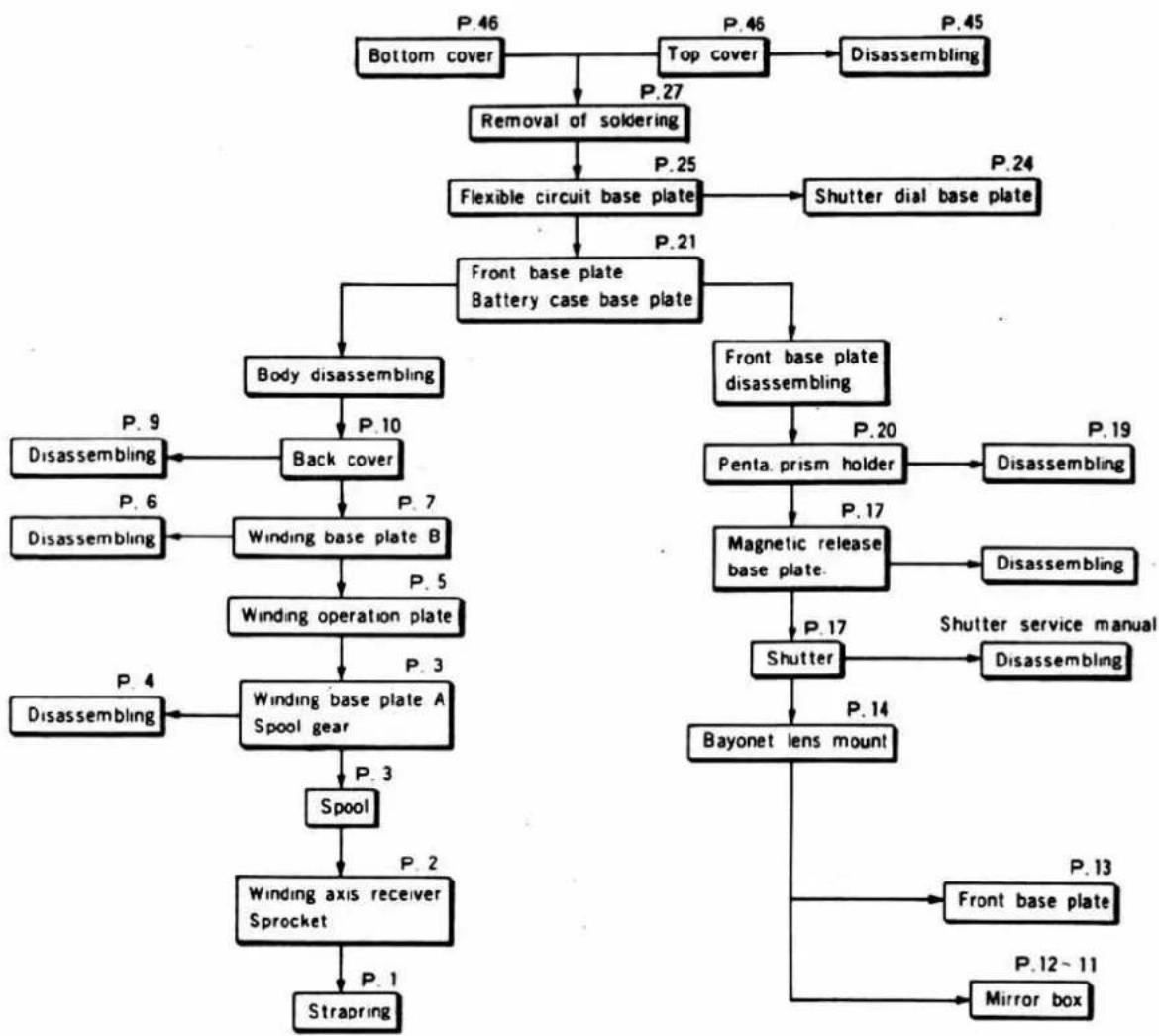
flowchart
graph TD
    A["Bottom cover"] --> B["Removal of soldering"]
    B --> C["Flexible circuit base plate"]
    C --> D["Front base plate Battery case base plate"]
    D --> E["Body disassembling"]
    E --> F["Back cover"]
    F --> G["Winding base plate B"]
    G --> H["Winding operation plate"]
    H --> I["Winding base plate A Spool gear"]
    I --> J["Spool"]
    J --> K["Winding axis receiver Sprocket"]
    K --> L["Strapping"]

    subgraph Process Steps
        M["P. 9 Disassembling"] --> N["P. 6 Disassembling"]
        N --> O["P. 4 Disassembling"]
        O --> P["P. 3"]
        P --> Q["P. 2"]
        Q --> R["P. 1"]
    end

    subgraph Legend
        S["P. 46"] --> T["P. 45"]
        U["P. 27"] --> V["P. 25"]
        W["P. 21"] --> X["Shutter dial base plate"]
        Y["P. 20"] --> Z["Penta prism holder"]
        AA["P. 17"] --> AB["Magnetic release base plate"]
        AC["P. 14"] --> AD["Bayonet lens mount"]
        AE["P. 13"] --> AF["Front base plate"]
        AG["P. 12~11 Mirror box"]
    end
■ Assembling/Adjustment Procedures Chart
- Be careful with assembling/adjustment of body as following points. Because this camera's body is used resin.
- Creaner can use only FLONSOLVE or Alchol. Do not use thinner, ketone and ether.
- Use correct screws only and install to vartical against part. DO NOT OVERTIGHT.
- Use the countermeasure screw instead of the screw when screw hole is loosen. (See Parts list).
① Body part (P.1\~P.10)
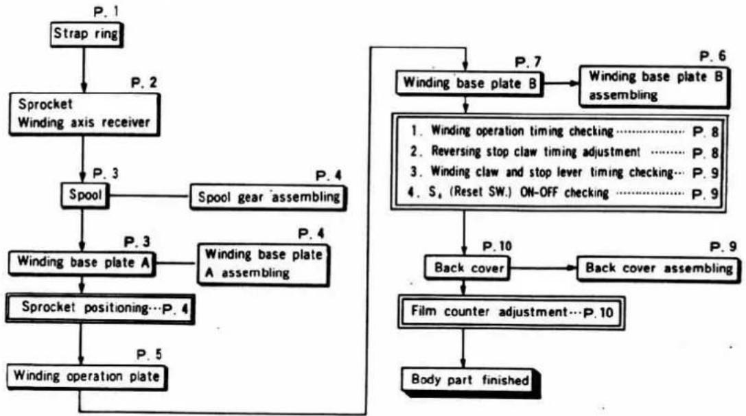
flowchart
graph TD
    A["Strap ring"] --> B["Sprocket Winding axis receiver"]
    B --> C["Spool"]
    C --> D["Winding base plate A"]
    D --> E["Sprocket positioning...P. 4"]
    E --> F["Winding operation plate"]
    F --> G["Body part finished"]

    H["Winding base plate B"] --> I["Winding base plate B assembling"]
    I --> J["1. Winding operation timing checking.... P. 8"]
    I --> K["2. Reversing stop claw timing adjustment.... P. 8"]
    I --> L["3. Winding claw and stop lever timing checking... P. 9"]
    I --> M["4. S₄ (Reset SW.) ON-OFF checking.... P. 9"]

    N["Back cover"] --> O["Back cover assembling"]
    O --> P["Film counter adjustment...P. 10"]
    P --> G

    style A fill:#f9f,stroke:#333
    style G fill:#f9f,stroke:#333
② Front base plate block (P.11-P.20)
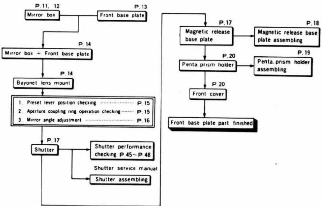
flowchart
graph TD
    A["Mirror box"] --> B["Front base plate"]
    B --> C["Mirror box + Front base plate"]
    C --> D["Bayonet lens mount"]
    D --> E["1. Preset lever position checking P.15"]
    D --> F["2. Aperture coupling ring operation checking P.15"]
    D --> G["3. Mirror angle adjustment P.16"]
    E --> H["Shutter performance checking P 45~P 48"]
    F --> H
    G --> H
    H --> I["Shutter service manual"]
    H --> J["Shutter assembling"]
    K["Magnetic release base plate"] --> L["Penta. prism holder"]
    L --> M["Front cover"]
    M --> N["Front base plate part finished"]
    O["Magnetic release base plate assembling"] --> P["Penta. prism holder assembling"]
    P --> L
    Q["Preset lever position checking P.15"] --> E
    R["Preset lever position checking P.16"] --> E
    S["Preset lever position checking P.17"] --> H
    T["Preset lever position checking P.18"] --> U["Pumpable base plate"]
    V["Preset lever position checking P.19"] --> W["Pumpable base plate"]
    X["Preset lever position checking P.14"] --> C
    Y["Preset lever position checking P.13"] --> B
③ To completion of body (P.21\~P.51)
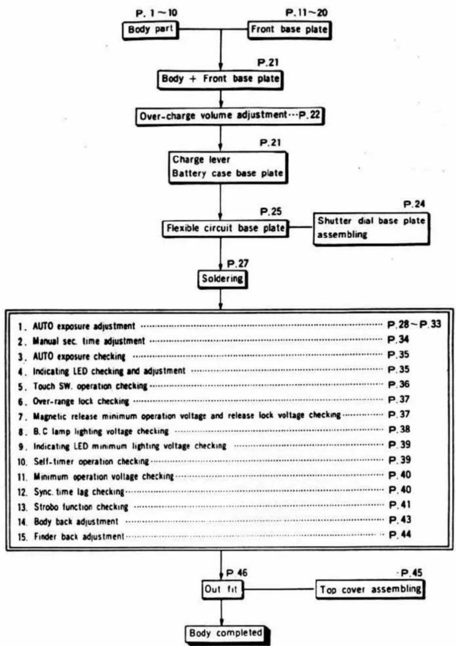
flowchart
graph TD
    A["Body part"] --> B["Body + Front base plate"]
    B --> C["Over-charge volume adjustment...P.22"]
    C --> D["Charge lever Battery case base plate"]
    D --> E["Flexible circuit base plate"]
    E --> F["Soldering"]
    F --> G["Out fit"]
    G --> H["Body completed"]

    subgraph P.1~10
        I["P. 1~10"] --> J["Body part"]
        K["P.11~20"] --> L["Front base plate"]
    end

    subgraph P.21
        M["P.21"] --> N["Body + Front base plate"]
    end

    subgraph P.25
        O["P.25"] --> P["Flexible circuit base plate"]
        Q["P.24"] --> R["Shutter dial base plate assembling"]
    end

    subgraph P.27
        S["P.27"] --> T["Soldering"]
    end

    subgraph P.33
        U["AUTO exposure adjustment"] --> V["P.28~P.33"]
    end

    subgraph P.34
        W["Manual sec. time adjustment"] --> X["P.34"]
    end

    subgraph P.35
        Y["AUTO exposure checking"] --> Z["P.35"]
    end

    subgraph P.35
        AA["Indicating LED checking and adjustment"] --> AB["P.35"]
    end

    subgraph P.36
        AC["Touch SW. operation checking"] --> AD["P.36"]
    end

    subgraph P.37
        AE["Over-range lock checking"] --> AF["P.37"]
    end

    subgraph P.37
        AG["Magnetic release minimum operation voltage and release lock voltage checking"] --> AH["P.37"]
    end

    subgraph P.38
        AI["B.C lamp lighting voltage checking"] --> AJ["P.38"]
    end

    subgraph P.39
        AK["Indicating LED minimum lighting voltage checking"] --> AL["P.39"]
    end

    subgraph P.39
        AM["Self-timer operation checking"] --> AN["P.39"]
    end

    subgraph P.40
        AO["Minimum operation voltage checking"] --> AP["P.40"]
    end

    subgraph P.40
        AQ["Sync. time lag checking"] --> AR["P.40"]
    end

    subgraph P.41
        AS["Strobo function checking"] --> AT["P.41"]
    end

    subgraph P.43
        AU["Body back adjustment"] --> AV["P.43"]
    end

    subgraph P.44
        AW["Finder back adjustment"] --> AX["P.44"]
    end

    subgraph P.45
        AY["P. 46"] --> AZ["Out fit"]
        BA["P. 45"] --> BB["Top cover assembling"]
    end
1
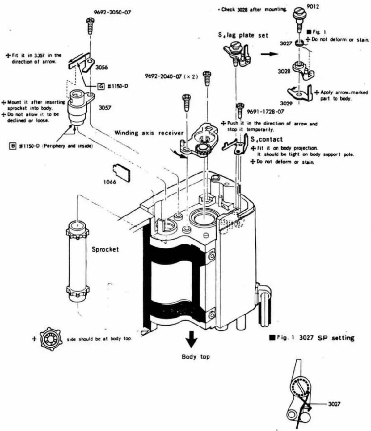
① Strap ring · Light shielding packing
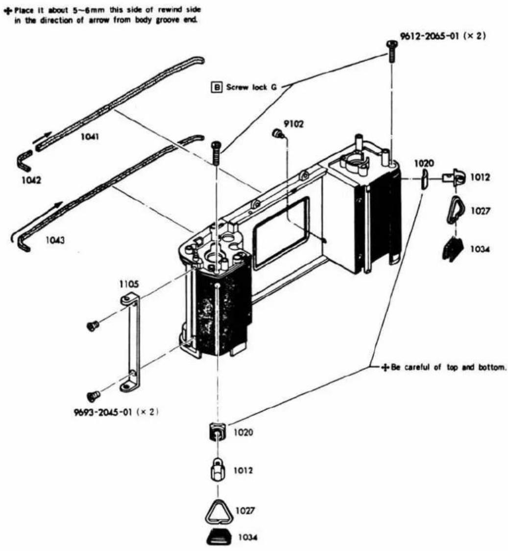
② Sprocket·Winding axis receiver·S4 (Reset SW.)
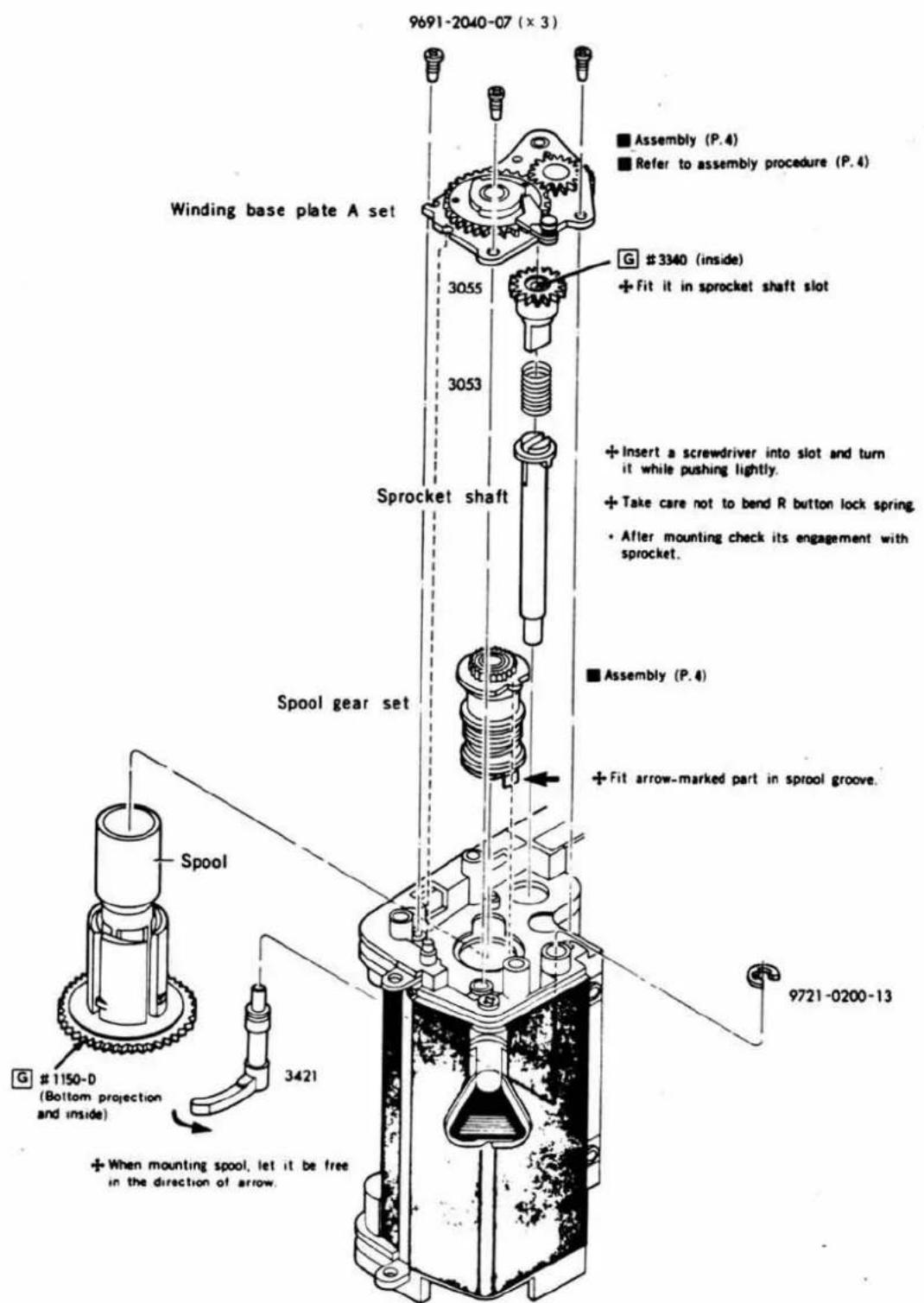
③ Spool·Winding base plate A set
■ Spool G set assembly
Winding base plate A set assembly
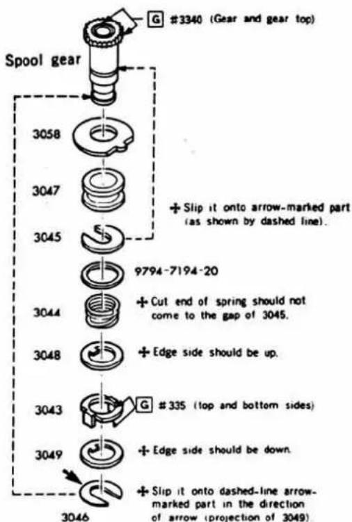
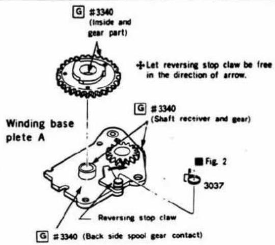
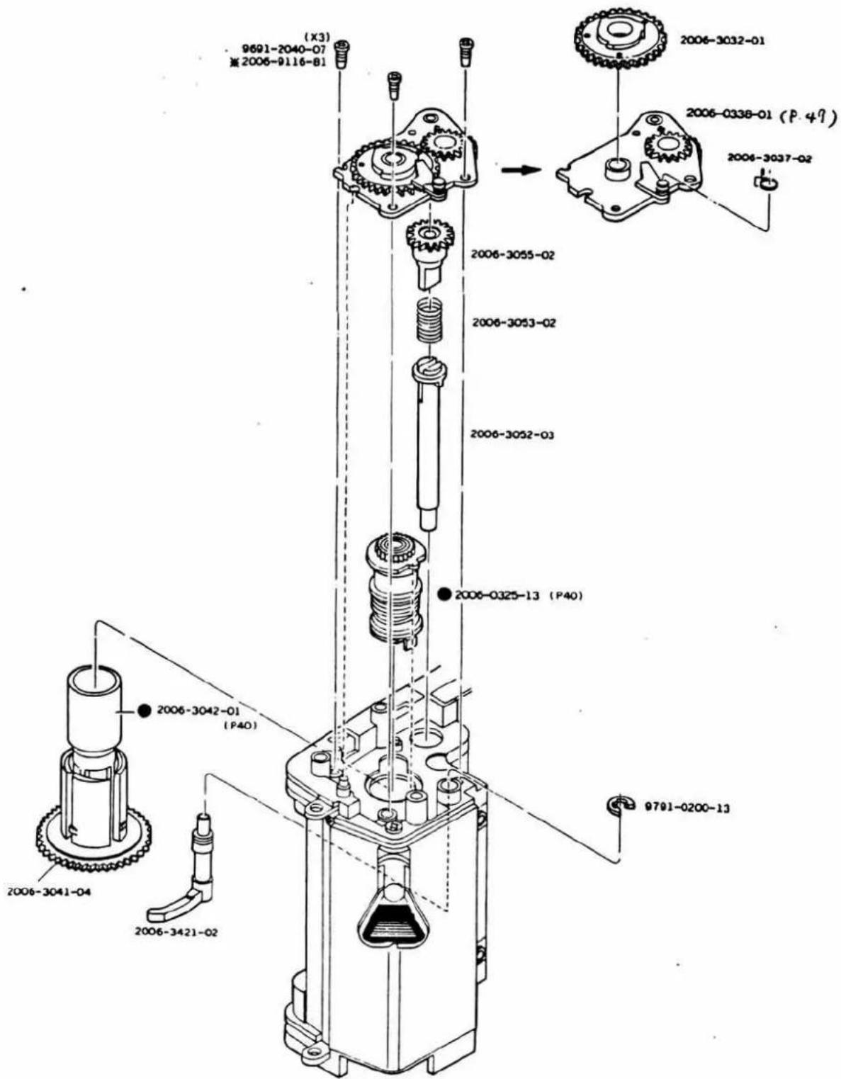
Fig. 2 3037 SP setting
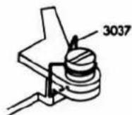
■ Winding base plate A set assembly (Sprocket positioning)
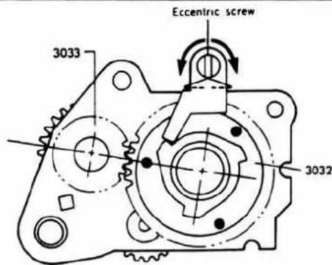
- Matching the punch mark on 3032 with the line connecting 3032 center to 3033 center of winding base plate A set, make the adjustment by eccentric screw so that reversing stop claw touches the notch of 3032.
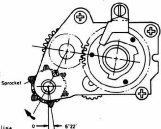
- Holding sprocket claw in the position as illustrated, fit sprocket gear projection in sprocket shaft groove, and thus mount the winding base plate A set as in (1).
- Checking
- When spool is turned clockwise, each gear and sprocket should rotate smoothly.
- When spool is rotated once and reversing stop claw is fitted in the notch of 3032, sprocket and each gear should be in the positions as illustrated. When sprocket has been returned in the direction of arrow, it should be at "0" position.
- Pushing R button should cause sprocket to idle, and R button should become released when spool is turned.
④ Winding operation plate set
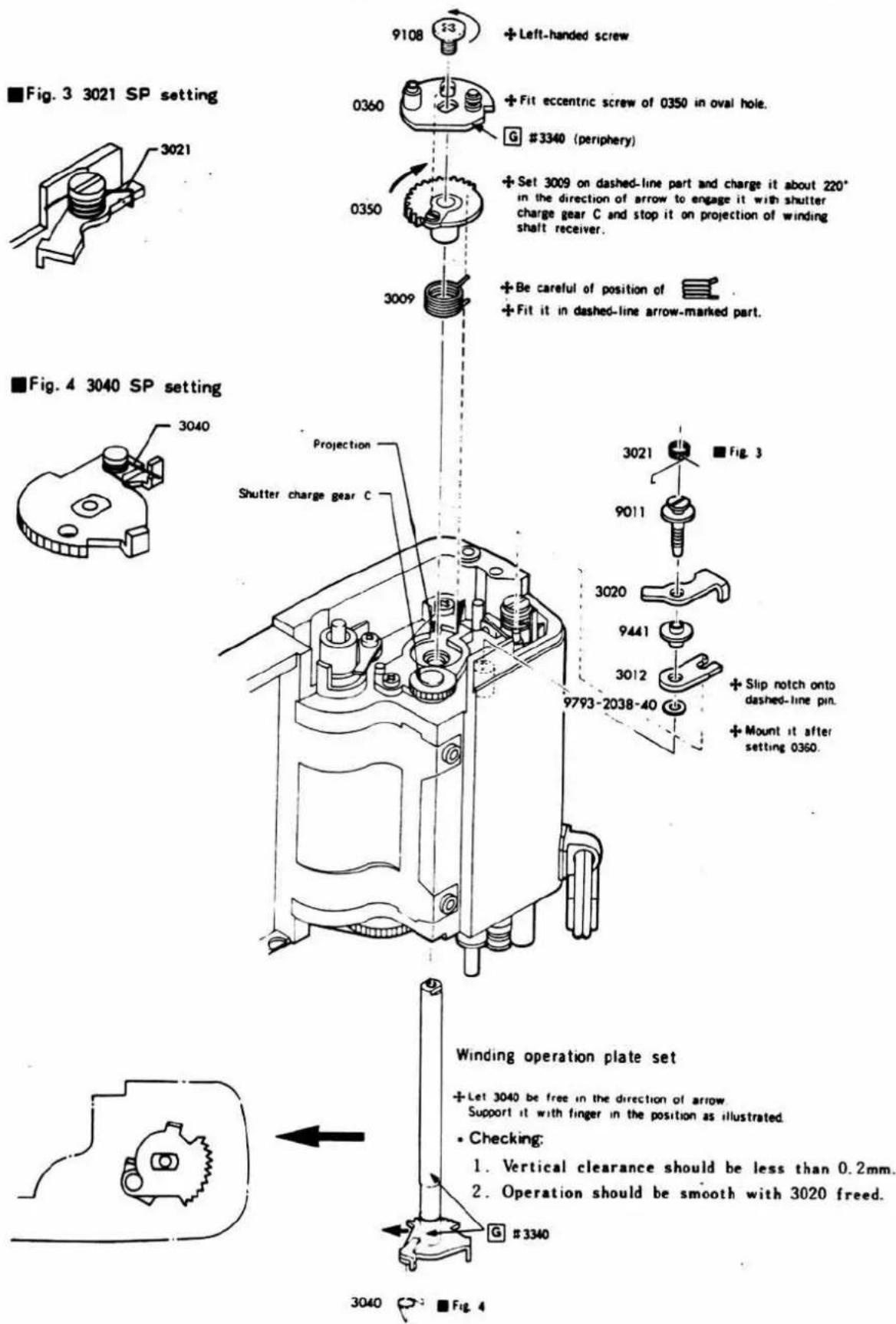
■ Winding base plate B assembly
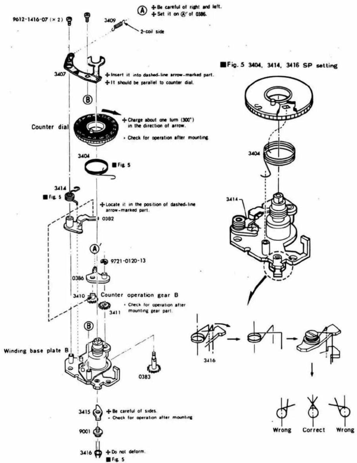
⑤ Winding base plate B set
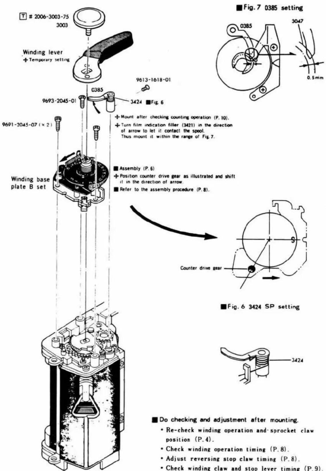
■ Do checking and adjustment after mounting.
- Re-check winding operation and-sprocket claw position (P.4).
- Check winding operation timing (P.8).
- Adjust reversing stop claw timing (P.8).
- Check winding claw and stop lever timing (P.9).
- Check S_4 (winding SW.) ON-OFF operation (P.9).
■ Winding base plate B set assembly procedure
-
Let reset lever (3020) be free and charge winding operation plate set about 90°. Then hold shutter charge gear C with finger.
-
Fit zero return lever in body notch. Then engage counter operation gear A set (0383) with winding gear (3032).
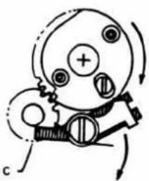
natural_image
Diagram of a mechanical device with gears and rotating arrows (no text or symbols)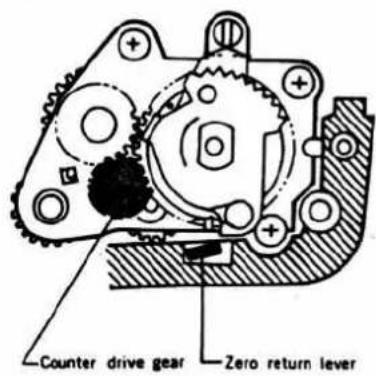
Shutter charge gear C
■ Winding operation timing checking
- Slowly do winding. Then, winding operation lever A (3415) should stop winding operation plate set. If it is defective, check winding operation lever and spring shape. (P. 6)
- Also, winding operation lever should become disengaged within 1^20' ± 1^ (about 0.05 0.3mm ) before completion of winding.
If timing is wrong, adjust the position of winding base plate B set.
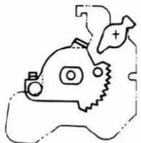
natural_image
Simple line drawing of a cartoon character with a fish and gear (no text or symbols)(Before winding)
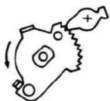
natural_image
Simple line drawing of a mechanical component with no text or symbols(During winding)
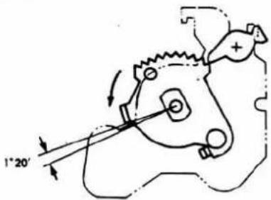
(Winding operation timing)
■ Reversing stop claw timing adjustment
Adjustment: Make the adjustment by eccentric screw so that reversing stop claw starts acting just before (20'→about 0.05mm) disengagement of winding operation lever when winding is slowly done and the claw completely stops reversing motion when winding has been completed.
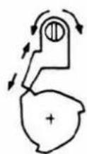
(Reversing stop claw starts acting.)
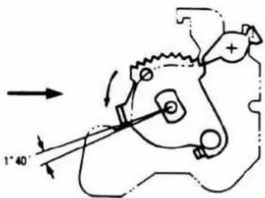
(Winding operation lever position.)
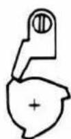
(Reversing stop claw is completely acting.)

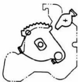
natural_image
Simple line drawing of a stylized animal head with no text or symbols(Winding is completed.)
Checking: Timing should be as follows:
Reversing stop claw starts acting Winding operation lever is disengaged Reversing stop claw is completely acting (winding completed)
Winding claw and stop lever timing checking
Slowly return the winding lever after completion of winding. Then, the timing should be as illustrated below.
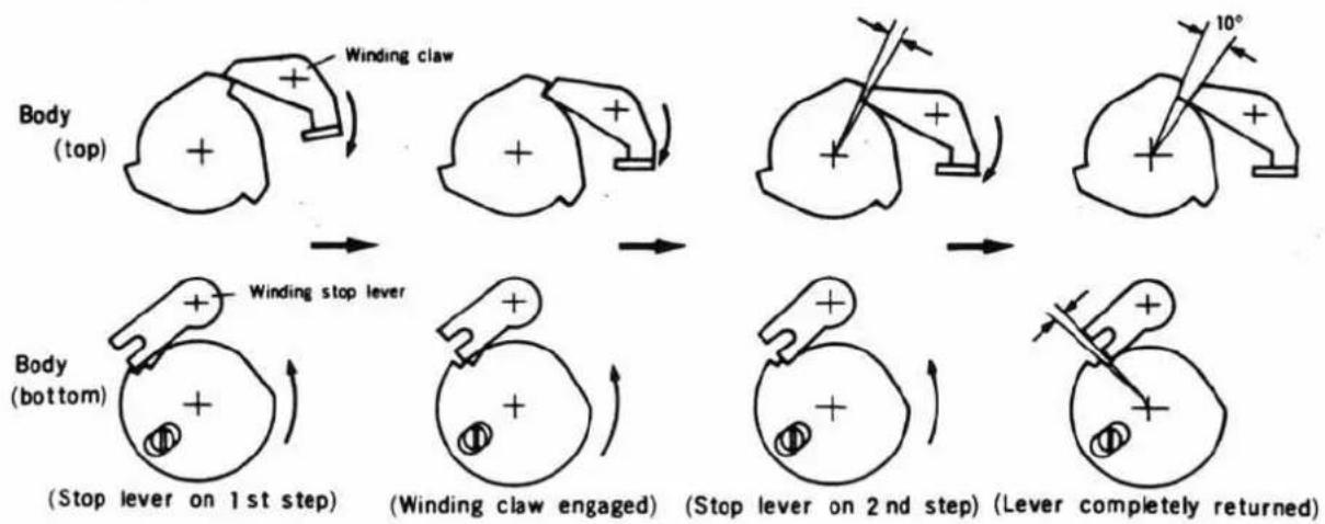
flowchart
graph TD
    A["Body (top)"] --> B["Winding claw"]
    B --> C["→"]
    C --> D["→"]
    D --> E["→"]
    E --> F["→"]
    F --> G["→"]
    G --> H["→"]

    I["Body (bottom)"] --> J["Winding stop lever"]
    J --> K["(Stop lever on 1st step)"]
    K --> L["(Winding claw engaged)"]
    L --> M["(Stop lever on 2nd step)"]
    M --> N["(Lever completely returned)"]
Winding operation lever should return while stop lever moves from 1st to 2nd step.
S4 (Reset SW.) ON-OFF checking
- Connect circuit tester to S_4 contact (3026) and S_4 lag plate (3029).
- When winding lever is slowly returned after completion of winding, it should be OFF with stop lever rested on the 1st step and ON with the lever rested on the 2nd step.
If the timing is wrong, check and adjust contact position and bending.
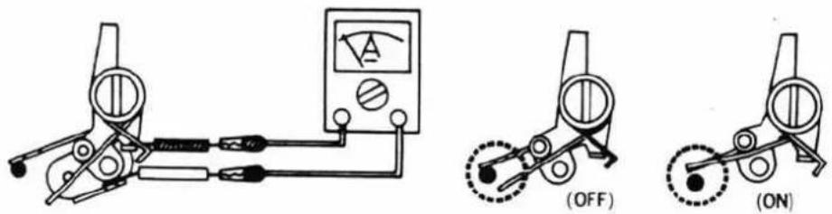
Back cover assembly
+ Be careful of top and bottom.
- Check operation after mounting.
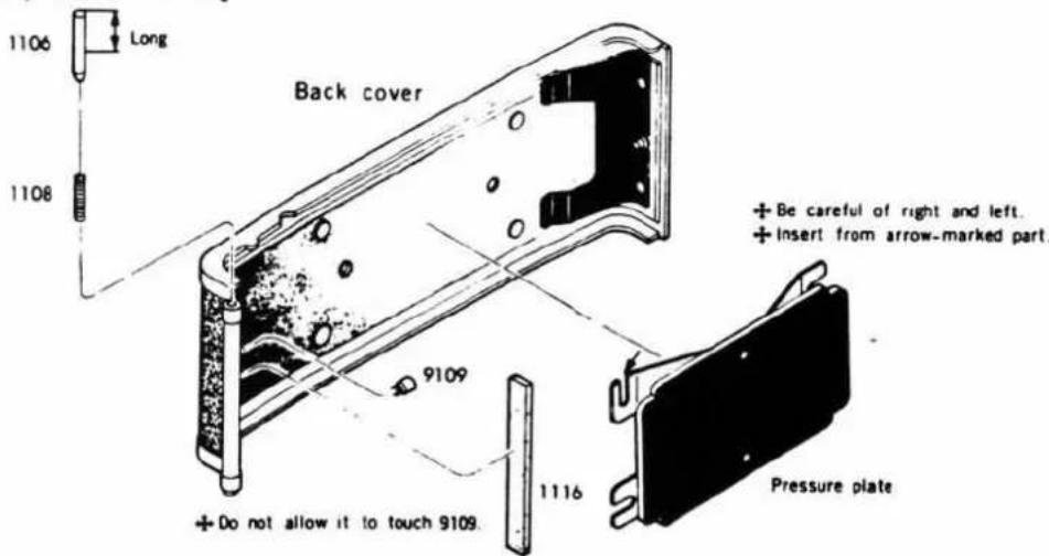
⑥ Back cover·Rewinding axis receiver set
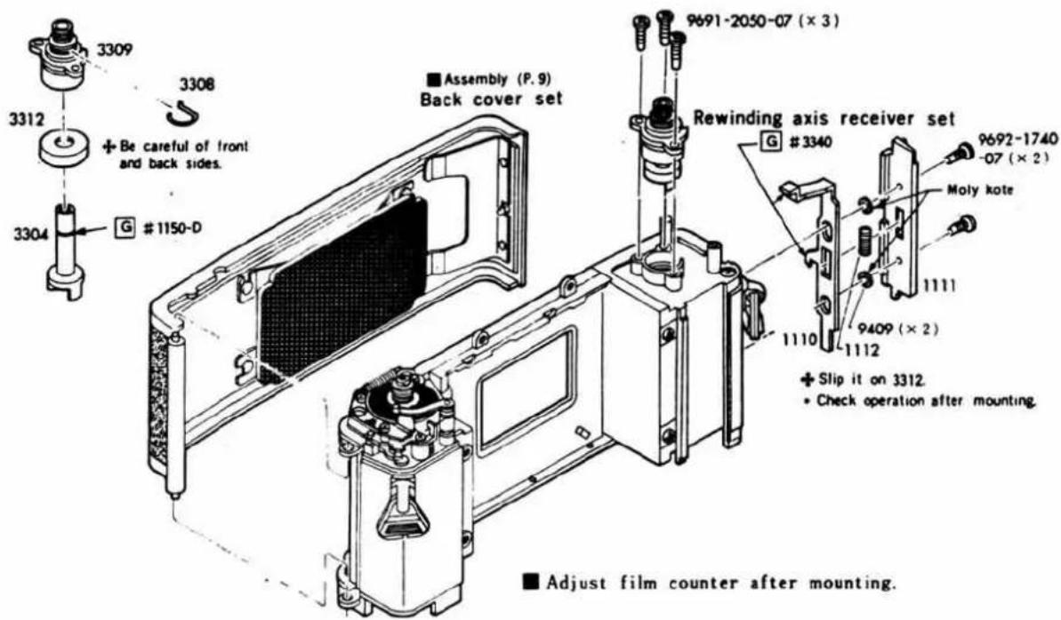
■ Film counter adjustment
- When back cover is closed, counter drive gear (3410) shaft should be in the first groove of counter ratchet (3403). If deflected, adjust counter index (3407) position.
- At center of "S" of counter dial should be "▲" of counter index (3407). If deflected, adjust counter index (3407) position.

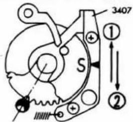
-
V-groove of counter drive gear (3410) should be positioned as illustrated below. If deflected, adjust it according to the procedure on Page 7.
-
Counter drive gear (3410) should be engaged with counter ratchet (3403) at the height as illustrated below. If deflected, check and adjust counter index (3407).
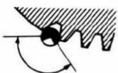
3410 and groove position.
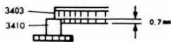
3410 and 3403 engagement
- Checking: Do winding twice from position "S". Then, counter should indicate "1". When further winding is done, there should be no skip, double feed, standstill, etc. Also, returning operation should be smooth.
7 Mirror box I
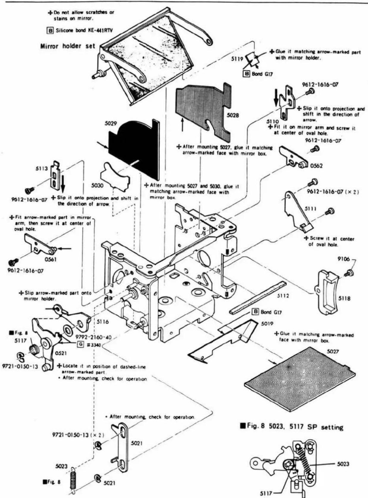
■ After adjusting mirror edge, apply Ⓗ screw lock G to set-screws 0561, 0562, 5110, 5111, 5113.
⑧ Mirror box Ⅱ
• After completing assembly, check for operation according to the following procedure.
- Cock mirror return lever in the direction of arrow until it is locked by mirror return lever locking claw.
- Shift release bar in the direction of arrow. Then preset lever operates to raise mirror.
- When mirror return locking claw is pushed in the direction of arrow, mirror and preset is returned.
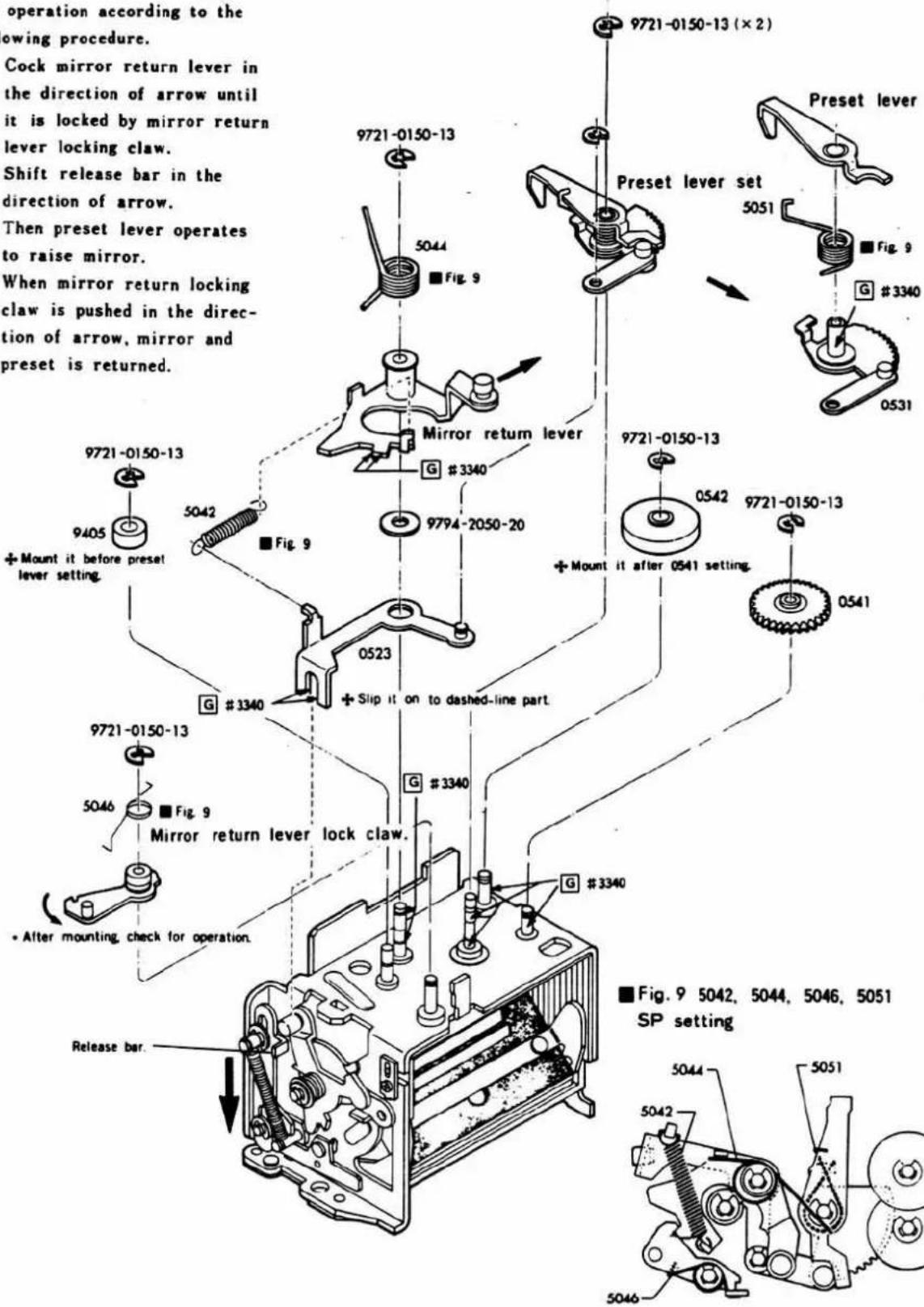
9 Front base plate
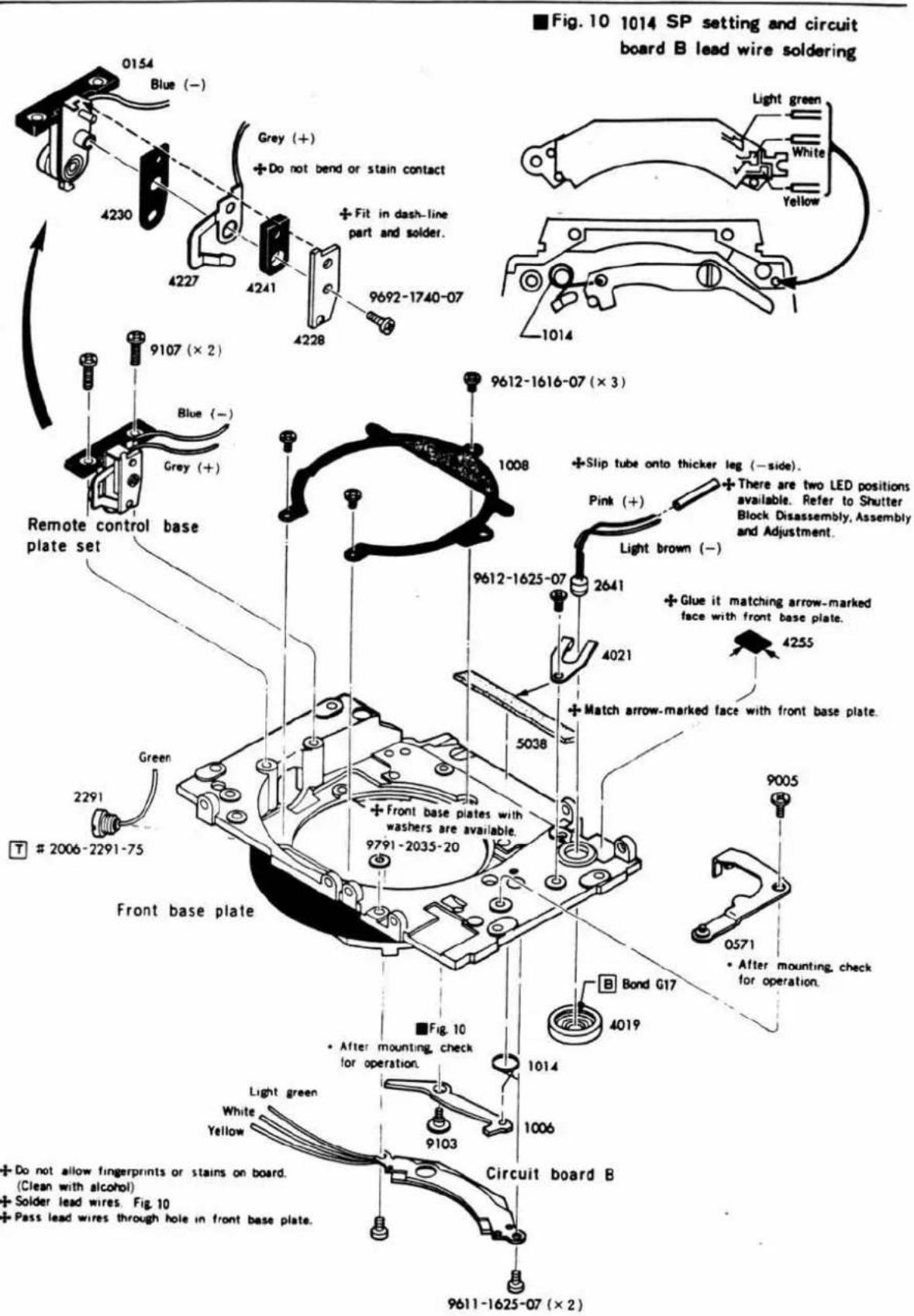
10 Front base plate set Bayonet lens mount
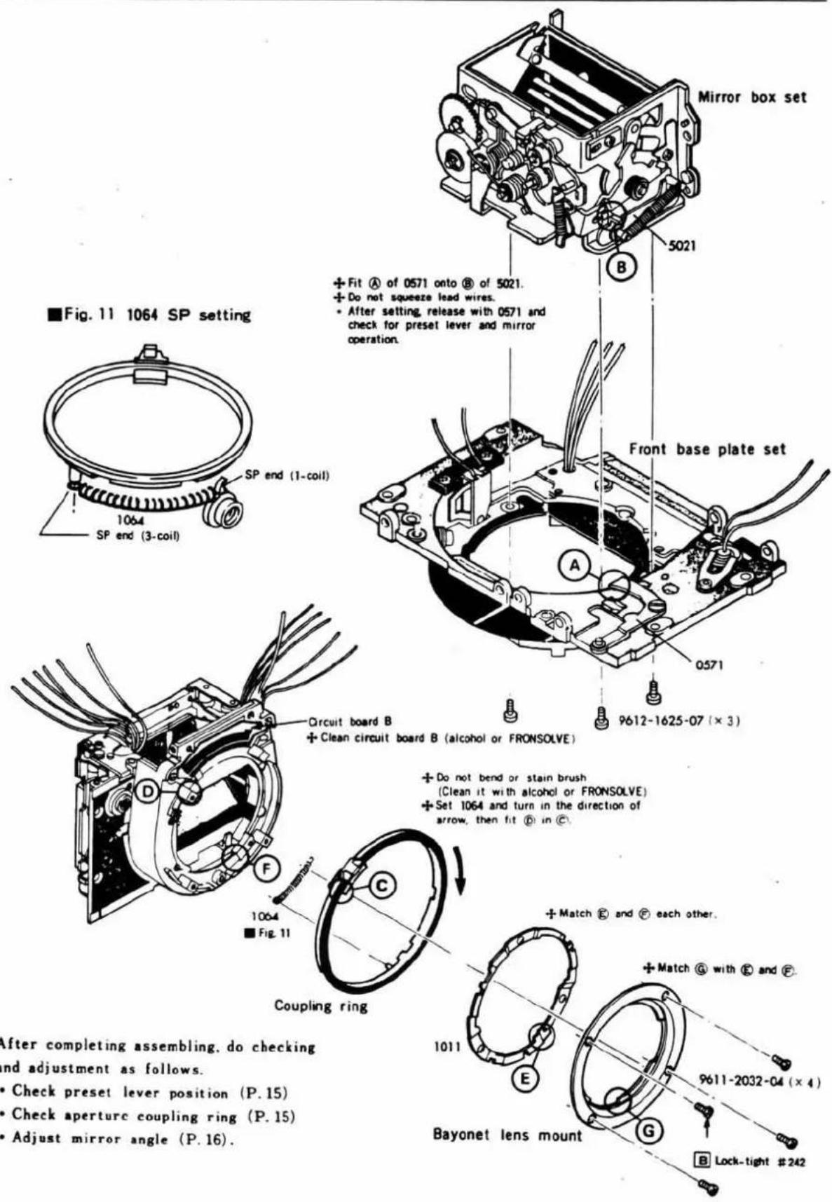
Preset lever position checking
■ Measuring instrument: Standard lens (50mm F 1.4)
- Mount standard lens with minimum aperture setting. The aperture should become released when mirror return lever lock claw (0522) is disengaged. (Preset lever: over 7.7 mm)
- When mirror return lever (0524) is cocked until stopping on 0522, aperture should become released. (Preset lever: over 6.7 mm)
- With release operation lever C (0571) released, preset lever operated, and mirror raised, aperture should be at minimum setting. (Preset lever: below 0)
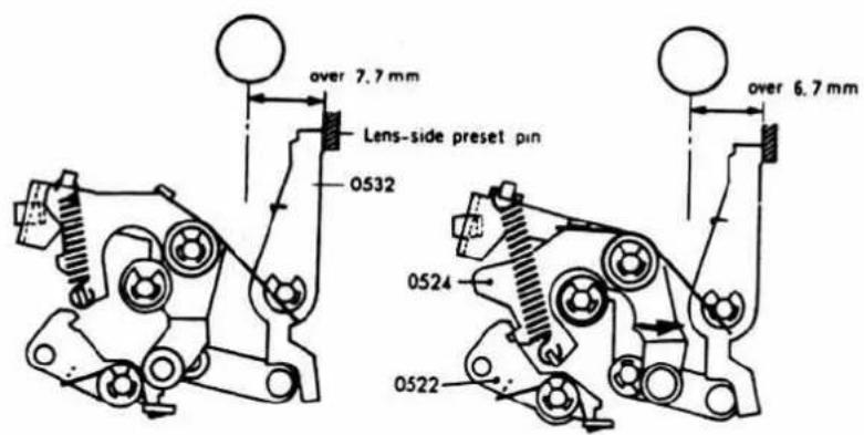
Standard
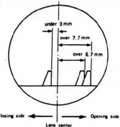
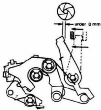
Aperture coupling ring
■ Measuring instruments: Circuit tester.
Standard lens (50 mm F 1.4)
- Operate aperture coupling ring up to the stop position in the direction of arrow and return it slowly. Then, it should not be forced back by coupling ring spring (1064) and the operation should be smooth with out abnormal noise.
- Mount standard lens, connect circuit board B (0152) leads (light green and yellow) as illustrated below, operate aperture ring.
Then, there should be no skip or standstill of resistance value. (Small resistance with
aperture opened, large resistance with minimum aperture.)
-
Also connect leads (white and yellow) as illustrated below. Then, there should be no skip or standstill of resistance value. (Large resistance with aperture opened, small resistance with minimum aperture.)
-
Lightly push coupling ring claw in the direction of arrow. Then, there should be no skip or standstill of resistance value.
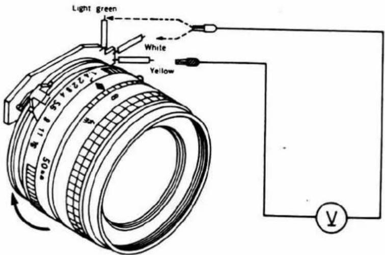
■ Mirror angle adjustment
■ Measuring instrument: Mirror angle adjuster (Model MA-II)
Standard value : 45^ ± 20'
- Mirror position (height) adjustment
a. Set mirror box and front base plate assembly on the measuring instrument. Place it opposite to the mirror height gauge.
Then make the position adjustment by inserting a screwdriver (with thick end, which doesn't touch flare preventive seat) into adjusting hole of mirror stopper (5111) so that gauge end is matched with mirror end.
b. After adjustment, tighten mirror stopper set-screw and check for deflection.
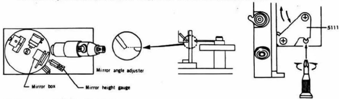
- Mirror angle (45°) adjustment.
a. Put mirror box opposite to auto meter, and let mirror support stopper A (5110) and B (5113) be free in the direction of arrow.
b. Look into auto meter and make the adjustment by inserting screwdriver into adjusting hole of mirror operation lever B shaft base (0561, 0562) from mirror box side so that the chart image center comes to the cross.
c. Tighten set-screw of mirror operation lever shaft base, and then check.
d. After adjusting mirror angle, looking into auto meter to see that the chart image stays on the cross, shift mirror auxiliary stopper A (5110) B (5113) in the direction opposite to te arrow so that it comes in contact with mirror operation lever pin (9215) and mirror holder contact pin (9216), and then tighten set-screws
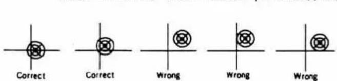
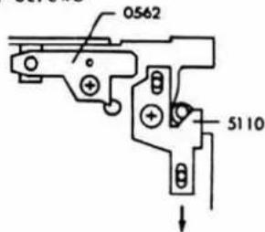
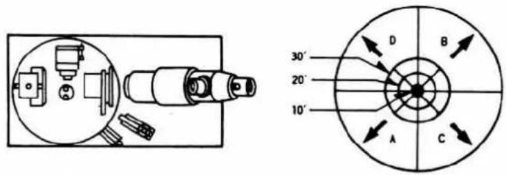
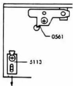
• Mirror operation checking
Operate mirror several times from back of mirror box. Then check that chart image is within standard value (45° ± 20') and that chart image shows no change.
Check if mirror is declined or mirror height is changed.
■ After checking mirror operation, apply screw-lock to each set-screw.
[1] Shutter·Magnetic release base plate
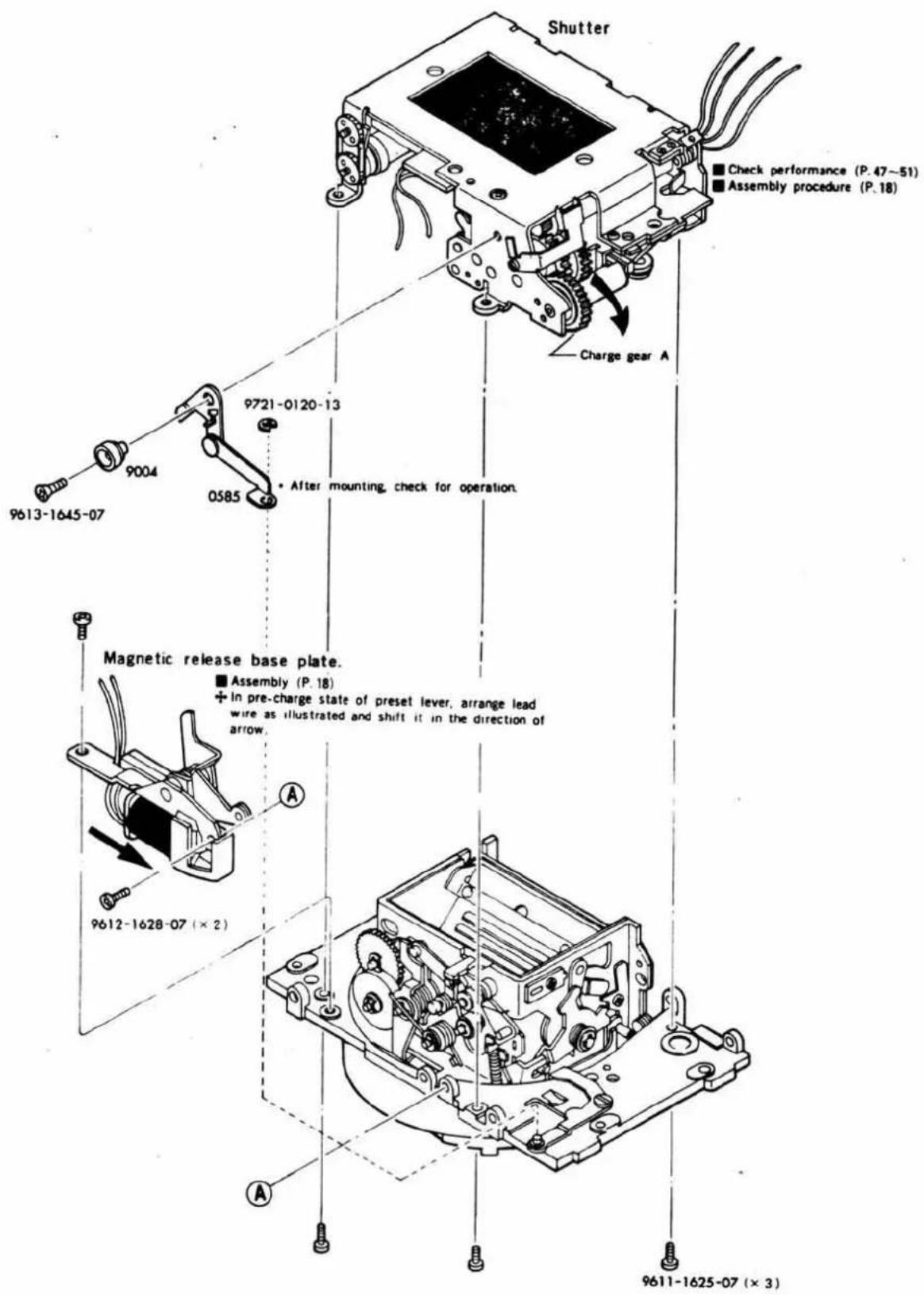
■ Magnetic release base plate assembly
Fig. 12 2039 SP setting
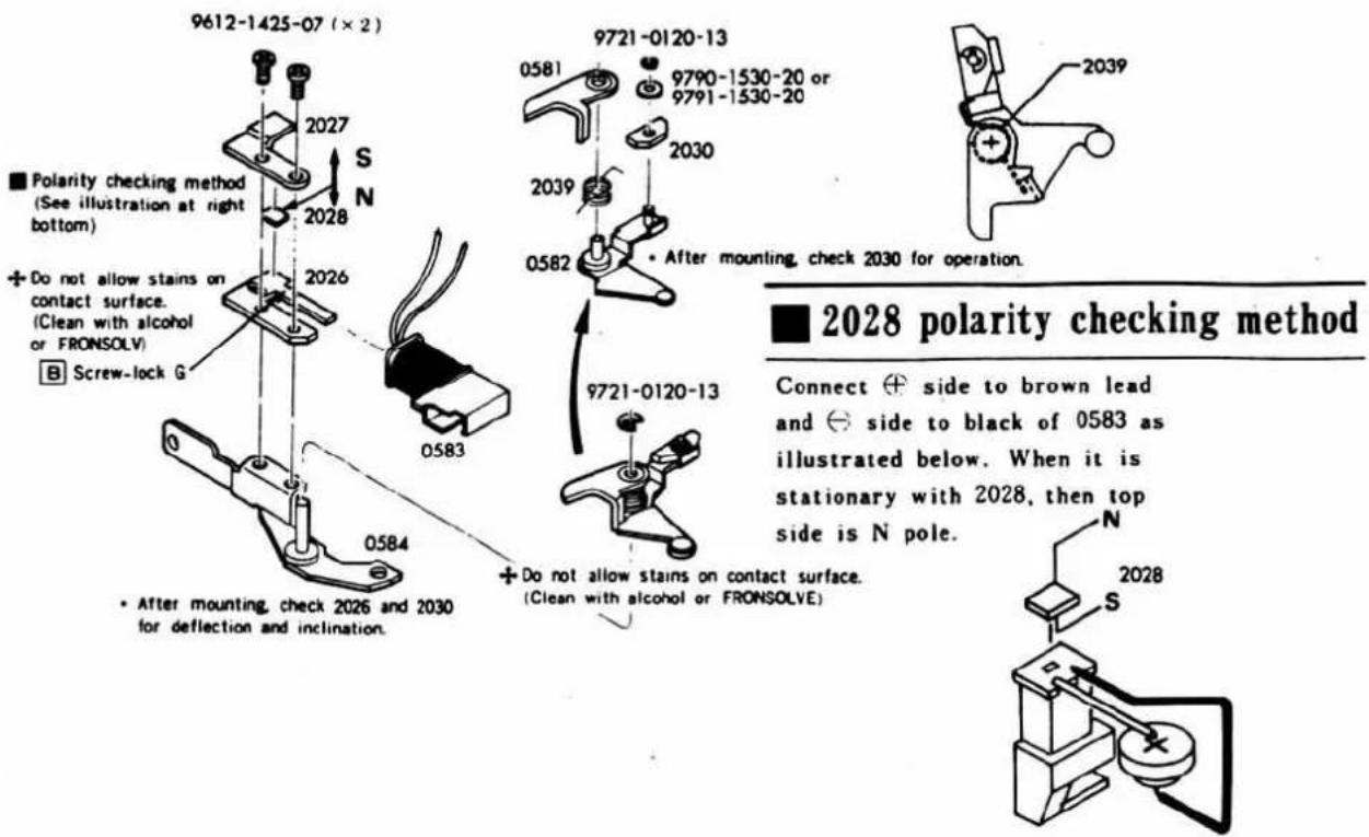
■ Shutter assembly procedure
- Arrange lead wires of shutter block and front base plate as illustrated below.
- Let mirror return lock claw (0522) be free on front base plate side to make it in pre-charge state. (P. 17)
- On shutter block side, operate charge gear A (2105) in the direction of arrow and mount shutter block in the state of winding completed. (P. 17)
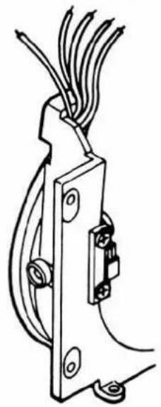
natural_image
Technical line drawing of a mechanical clamp or bracket with wires and mounting feet (no text or symbols)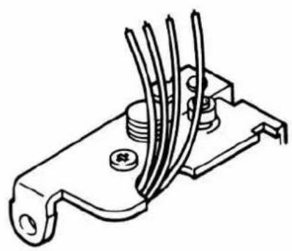
natural_image
Technical line drawing of a mechanical component with multiple blades and mounting holes (no text or symbols)• After mounting, cock mirror return lever (0524) to release, and check that shutter operate properly.
Pentagon holder assembly
Fig. 13 5016 SP setting
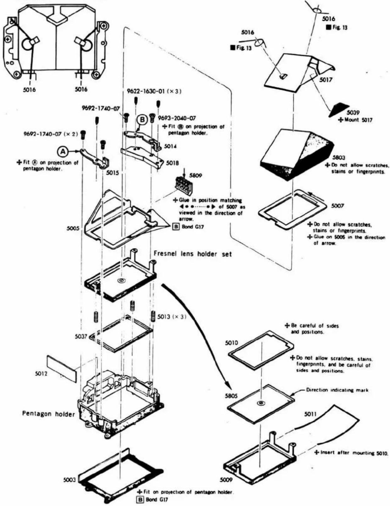
12 Pentagon holder set·Front cover
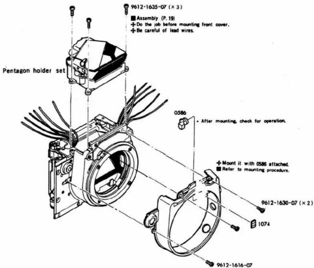
■ Front cover mounting procedure
- Widen front cover in the direction of arrow and fit it in remote control terminal (4232) and synchro terminal (2291) on the right, and in aperture coupling ring (0120).
- Operate aperture coupling (0120) to the right to fit it on the left side of front cover.
• Precautions for mounting
- Do not bend brush of aperture coupling ring (0120).
- If front cover connection is broken, secure it with set-screws, taking care not to allow any difference in level.
- Checking after mounting
- Remote control terminal (4232) and synchro terminal (2291) should be fitted in front cover.
- Lens lock button (0586) should be smooth in operation.
- Operate coupling ring to the right up to stop position and slowly return it. Then, it should move smoothly without being forced back by coupling ring SP (1064) or abnormal noise. (See Page. 15.)
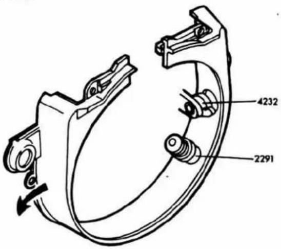
[13] Front base plate·Charge lever·Battery case base plate set
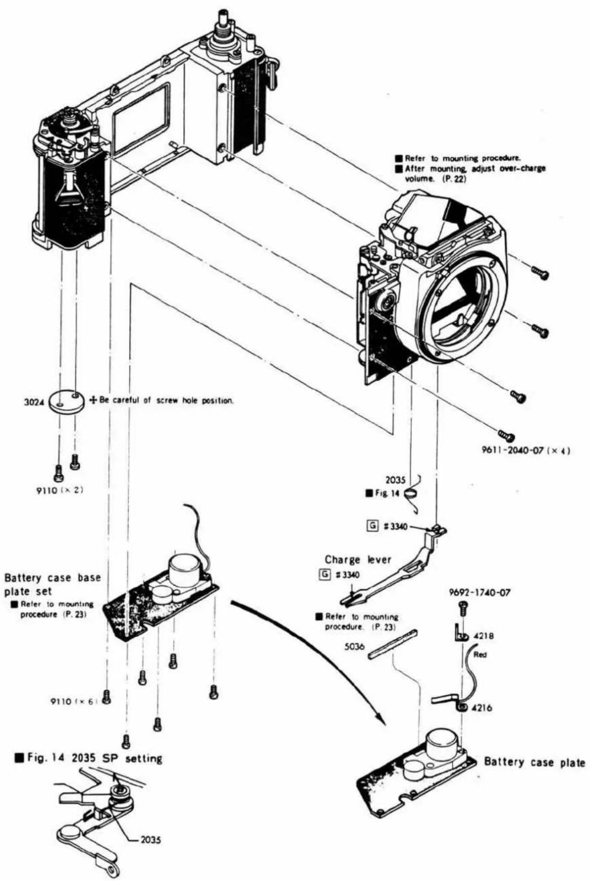
Front base plate set mounting procedure
-
Mount front base plate set, with body and shutter in the state of pre-charge, and temporarily fasten front base plate set-screws and shift the plate in the direction of arrow, then tighten the set-screws in the order of numbers.
-
Shift winding shaft receiver (0310) in the direction of arrow so that the - mark of charge gear A (2105) is engaged with shutter charge gear C (3016) as illustrated below, and then tighten up set-screws.
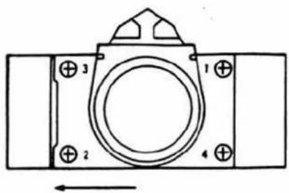
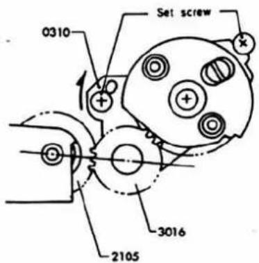
Over-charge volume adjustment
• Over-charge or under-charge checking
-
Set rewinding lever (3020) free and do winding. (Only shutter is charged). If winding is heavy towards ending, shutter is over-charged. (Do not wind by force.)
-
Charge mirror return lever (0524). (It is charged on mirror box side.)
-
Operate release connecting lever C (0571) to release shutter. If shutter is not released with mirror raised, it is under-charged. At that time, mirror is kept raised. Then releasing mirror return lever lock claw (0522) causes mirror to be lowered and mirror box to get into the state of pre-charge. However, shutter is still under-charged.
• Over-charge volume adjustment
-
Do winding to operate 2nd curtain stop lever (0219) in the direction of arrow (charge on shutter side). Adjust eccentric screw (9281) of shutter charge gear D (0350) at the bottom of body so that sprocket idle gear (3034) is over-charged by 1 tooth (3°40') from the position of control base plate (0202).
-
If adjustment is impossible, re-adjust in accordance with front base plate mounting procedure.
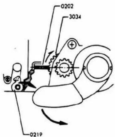
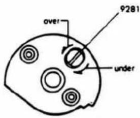
Charge lever mounting procedure
- Cock mirror return lever (0524).
- Insert charge lever (3016) into charge pin (9294) of charge control plate (0360), then set release operation lever spring (2035) as illustrated below.
- Set charge lever (3016) on charge pin (9228) of mirror return lever (0524). Caution: Take care not to deform charge lever and mirror return lever.
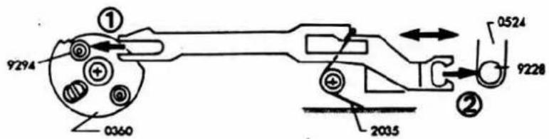
• After mounting, do the following checks.
- Winding operation is smooth without catching or the like.
- Shutter and preset are charged with over-charge volume assured.
- Release magnet does not become loose due to winding shock or the like.
- When release connecting lever-C (0571) is operated, preset mirror mechanism operates and shutter is release. But the curtain does not open when shutter is at high speed condition.
- After releasing, when winding stop lever is set free by charge lever, the next winding is possible.
- Clearance between charge lever (3016) and charge pin (9228) is not excessive.
Battery case set mounting procedure
- Arrange lead wires on body side (green and black leads for shutter; brown and black leads for release magnet.) and red lead for battery case as illustrated below.
- Tighten set-screws of battery case in the order of numbers.
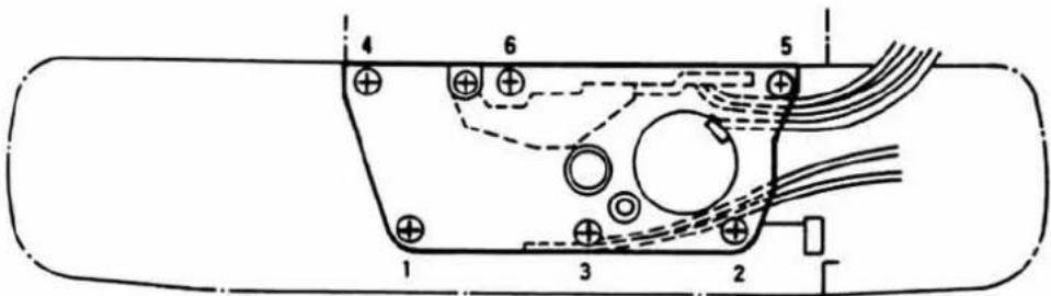
- After mounting, temporarily fasten lower cover. Make sure that winder (8731-200) can be smoothly mounted and winder-side connecting terminal and body-side winder connecting terminal (9243) can be connected to each other.
■ Shutter dial base plate assembly
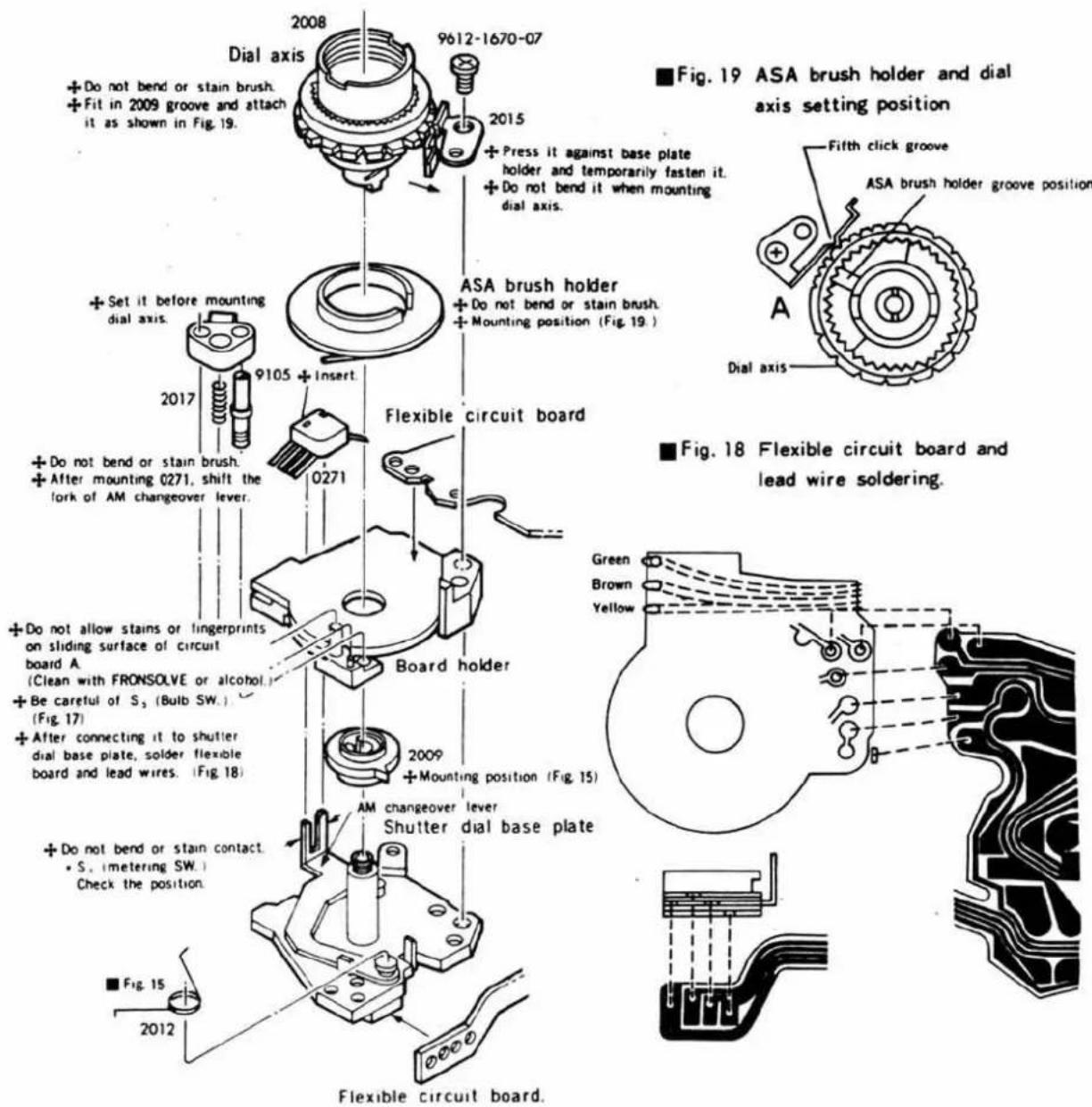
Fig. 15 2012 SP setting and 2009 position
Fig. 16 S₁ (metering SW.)
S₂ (release SW.) checking
Fig. 17 S, (bulb SW.) position
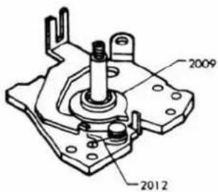
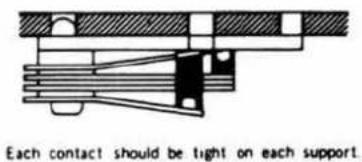
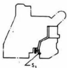
14 CdS board·Flexible circuit board
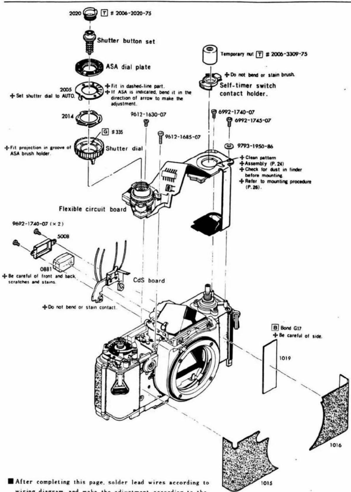
■ After completing this page, solder lead wires according to wiring diagram, and make the adjustment according to the procedure given on and after Page 28.
+Glue after finishing adjustment and checks given on and after Page.28.
■ Flexible circuit board mounting procedure
- Arrange body side lead wires as illustrated below, and temporarily fasten flexible circuit board under contacts A, B, C (1055, 1056, 1057) of CdS board.
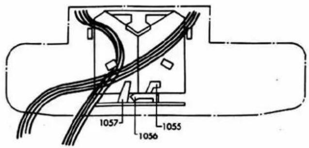
- Mount LED board with rewind axis receiver (3309) positioned at center.
• NOTE: Do not allow lead wires to be squeezed and LED board to become loose.
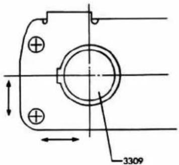
- Insert flexible circuit board on shutter dial plate side as illustrated below.
Temporarily fasten it with auto lock plate guide (2016) and two set-screws, and stop auto lock plate (2015) on dial axis (0272).
Adjust spring position so that click spring (2015) in fitted in click groove as illustrated.
- Checking: Slowly turn dial axis from right to left, then auto lock plate should get into lock position. When auto lock button is pushed again, it should be positioned in lock position.
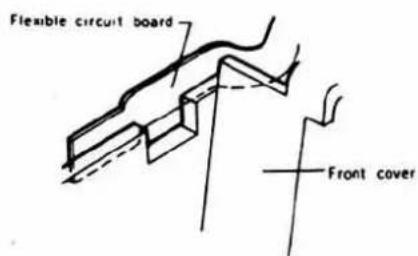
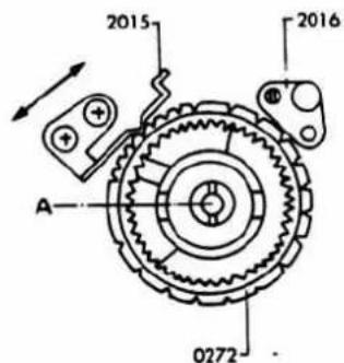
■ Wiring Schematic Diagram
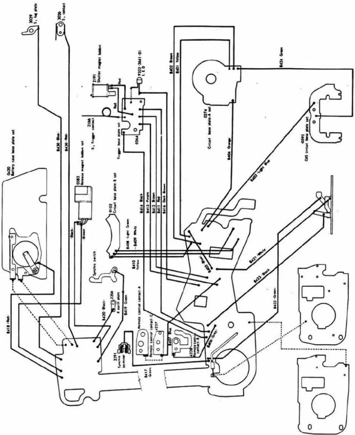
■ AUTO exposure adjustment
■ Variable resistor and fixed resistor adjustment.
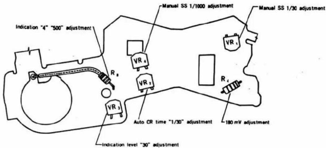
① Measurement of CdS resistance value and selection of R_1 , R_2
■ Measuring instruments:
: Digital tester (Type 2507)
: Luminescence box (Model L-222 or L-223)
: Standard lens (50 mm, F 1.4)
: ND filter (MINOLTA ND 50% FOR ADJUSTMENT)
■ Measuring method
- Disconnect green lead of CdS board (0591) and soldered R_1 and R_2 as illustrated below. Then connect lead wire for measurement to R_1 .
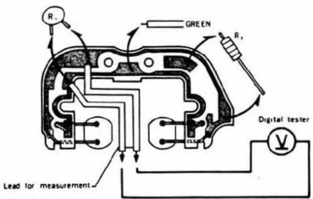
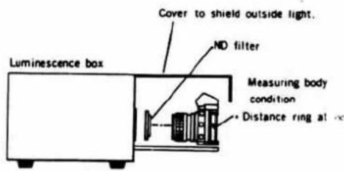
- Measurement of RmV5 (Resistance should be within 10\~40KΩ) Set digital tester range to "Ω", set ND filter on body and then measure resistance value at luminance EV 11 (ASA 100).
- Measurement of RHV10 (Resistance should be within 1.6\~5.8KΩ) With CdS connected as above, remove ND filter and measure resistance at luminance EV 15 (ASA 100).
■ Selection of R_1 , R_2
From resistance values of Rbv5 and Rbv10 obtained by CdS measurement, R_1 and R_2 can be calculated as follows:
- How to obtain from formula
$$ R _ {2} = R _ {\mathrm{RV}} 5 \left{\frac {1}{4} \left(\frac {R _ {\mathrm{BV}} 1 0}{R _ {\mathrm{BV}} 5}\right) ^ {0. 1 0 7 5} - \frac {R _ {\mathrm{RV}} 1 0}{R _ {\mathrm{RV}} 5} \right}. \tag {①} $$
$$ R _ {1} = \frac {\left(R _ {B V} 5\right) ^ {2}}{R _ {2}} \dots \tag {②} $$
Pick up resistances which are proximate to the obtained resistance values from the following table, and then solder R_1 , R_2 and lead wire (Green).
- NOTE: When R_2 is (-) in formula ①, the combination of CdS is defective.
When R_2 is larger than 1.8KΩ in formula ①, the combination of CdS is defective.
When R_2 is smaller than 0.11KΩ in formula ①, shortcircuit R_2 with lead wire.
| Calculating value of R_1 (KΩ) | R_1 used (KΩ) | Calculating value of R_1 (KΩ) | R_2 used (KΩ) |
| 300 > R_1 | (270 KΩ) | 0.245 > R_2 > | (0.22 KΩ) |
| 300 ≤ R_1 < 360 | (330 KΩ) | 0.245 ≤ R_2 < 0.3 | (0.27 KΩ) |
| 360 ≤ R_1 < 430 | (390 KΩ) | 0.3 ≤ R_2 < 0.36 | (0.33 KΩ) |
| 430 ≤ R_1 < 515 | (470 KΩ) | 0.36 ≤ R_2 < 0.43 | (0.39 KΩ) |
| 515 ≤ R_1 < 620 | (560 KΩ) | 0.43 ≤ R_2 < 0.515 | (0.47 KΩ) |
| 620 ≤ R_1 < 750 | (680 KΩ) | 0.515 ≤ R_2 < 0.62 | (0.56 KΩ) |
| 750 ≤ R_1 < 910 | (820 KΩ) | 0.62 ≤ R_2 < 0.75 | (0.68 KΩ) |
| 910 ≤ R_1 < 1100 | (1000 KΩ) | 0.75 ≤ R_2 < 0.91 | (0.82 KΩ) |
| 1100 ≤ R_1 < 1350 | (1200 KΩ) | 0.91 ≤ R_2 < 1.1 | (1 KΩ) |
| 1350 ≤ R_1 < 1650 | (1500 KΩ) | 1.1 ≤ R_2 < 1.35 | (1.2 KΩ) |
| 1650 ≤ R_1 < 2000 | (1800 KΩ) | 1.35 ≤ R_2 < 1.65 | (1.5 KΩ) |
| 2000 ≤ R_1 < 2450 | (2200 KΩ) | 1.65 ≤ R_2 | (1.8 KΩ) |
| 245 ≤ R_1 | (2700 KΩ) |
- How to obtain from table
a. Select value of R8v5 or proximate value from vertical axis.
b. Select value of Rsv10 or proximate value from horizontal axis.
c. Find the intersection of a and b.
The values thus obtained are R_1 , R_2 and lead wire (Green): R_1 at top and R_2 at bottom. Then solder R_1 and R_2 obtained from the table.
• NOTE: When R_2 is 0, connect lead wire to R_2 .
If the intersection of Rsv5 and Rsv10 is blank, the combination of CdS is defective.
(Ex.) R_Bv5=20.4K , R_Bv10=1.69K
a. Approximate value of 20.4KΩ = 20KΩ.
b. Approximate value of 3.69KΩ = 3.6KΩ.
c. Place 20KΩ on vertical axis and 3.6KΩ on horizontal axis. From the intersection,
R_1 : 1500KΩ and R_2 : 0KΩ can be obtained.
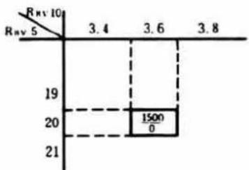
line
| X | Y | |---|---| | 19 | 1500/0 | | 20 | | | 21 | |■ Calculation Table
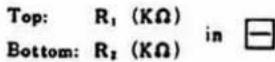
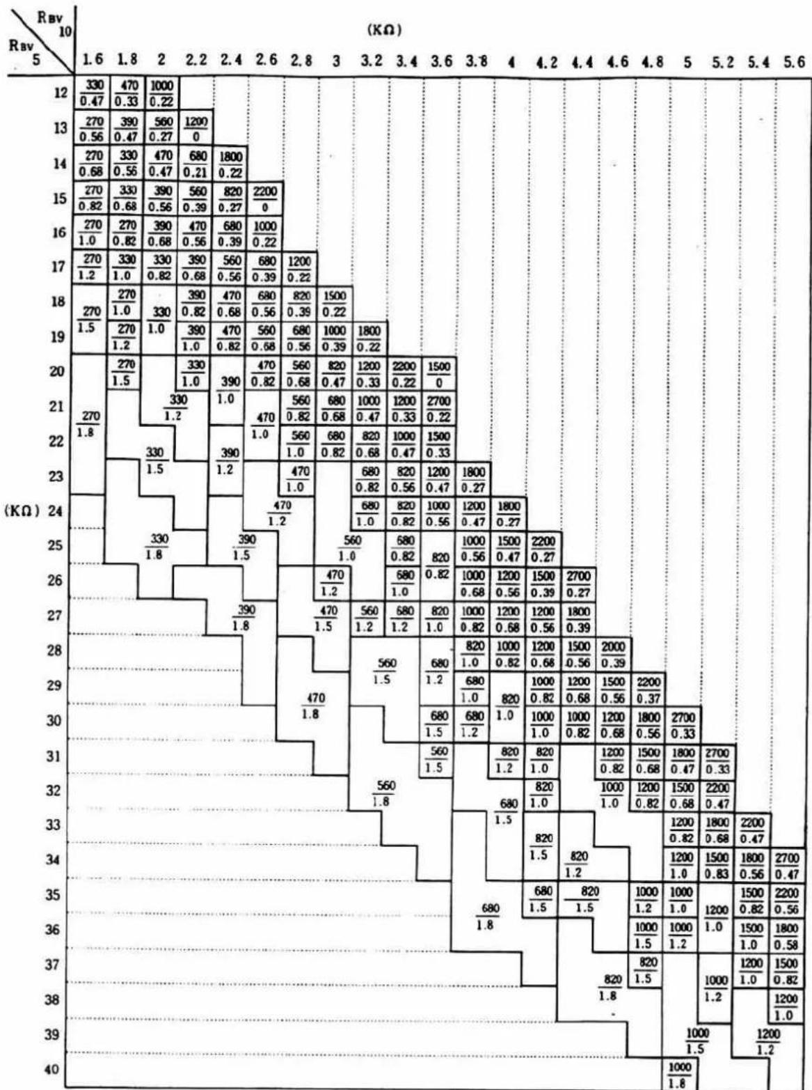
② Determination of R_4 -180 mA adjustment-
■ Measuring instruments:
: Camera standard tester (ST-5101) or
Constant voltage D.C power supply (Model E-1 or E-2)
: Resistance selector (Model RS-Ⅲ)
: Digital tester (Type 2507)
: Battery adapter (2006-0415-75)
■ Standard value: 180±2 mV
■ Adjustment procedure
- Disconnect R_4 as illustrated below. Connect lead wire for measurement to R_4 (terminals ⑱, ⑲ of IC-1) and then set it on the measuring instrument.
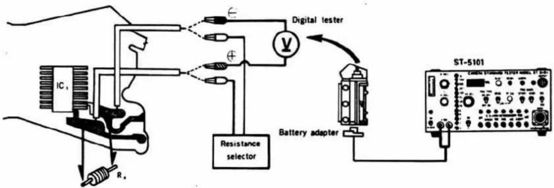
- Set power source voltage at 2.8V and metering switch ( S_1 ) to ON. Then select R_4 resistance by the following method.
a. Change the range of Rp resistance selector to select Rp resistance where the digital tester indicates around 180 mV.
b. From the obtained Rp resistance, select R_4 resistance which is proximate to 180 mV from the table below. Then solder it to terminals ⑱, ⑲ of IC-1.
| For example, when the resistance value of Rp resistance selector is 18 KΩ, the value indicated on digital tester is to be V 18 (mV). | Comparison of voltage (mV) | R_4 used (KΩ) | |
| V_18 - 180 ± 2 | 18 | ||
| Resistance of Resistance selector (KΩ) | Indication of digital tester (mV). | V_18 < 180 ≤ V_26 | 18 |
| V_30 < 180 ≤ V_24 | 22 | ||
| 18 | V_18 | V_24 < 180 ≤ V_30 | 27 |
| 20 | V_20 | V_30 < 180 ≤ V_34 | 33 |
| 24 | V_24 | V_36 < 180 < V_47 | 39 |
| 30 | V_30 | V_47 - 180 ± 2 | 47 |
| 36 | V_36 | V_47 < 180 ≤ V_62 | 56 |
| 47 | V_47 | V_62 < 180 < < V_100 | 68 |
| 62 | V_62 | V_62 < < 180 < V_100 | 82 |
| 100 | V_100 | V_100 - 180 ± 2 | 100 |
| 200 | V_200 | V_200 - 180 ± 2 | 200 |
| ∞ | V_∞ | V_200 < 180 < < V_∞ | 200 |
| V_200 < < 180 < V_∞ | 390 | ||
c. After soldering R, resistor, remove Rp resistance selector. Then make sure that indication of digital tester is 180 ± 2 mV.
(Ex.) When Rp resistance is 24KΩ, indication of digital tester is 175 mV; and when Rp is 30KΩ, the indication is 181 mV. V 24 = 175 < 180 < 181 - V 30 . Therefore, R _4 is 27 KΩ as obtained from the table.
③ Adjustment of VR₂ -AUTO Shutter speed adjustment-
■ Measuring instruments:
: Camera standard tester (ST-5101), or Digital time counter (TC-1) and Constant voltage D.C power supply (Model E-1 or E-2).
: Luminescence box (L-222 or L-223)
: Standard lens (50 mm F 1.4)
: ND filter (MINOLTA ND 50% FOR ADJUSTMENT)
: Battery adapter (2006-0415-75)
: Luminescence adjusting driver-B
■ Standard value: 32\~36ms
Luminescence = EV 10, ASA 100 (BV 5), ASA sensitivity = 100 (SV 5)
F-number = F 5.6 (AV 5)
■ Adjustment procedure
- Connect lead wires for measurement to terminal ⑩ (start signal) and ⑮ (stop signal) of IC₁ and then set it on the measuring instrument as illustrated below.
Ref. Digital time counter (TC-1) and constant voltage D.C power supply setting.
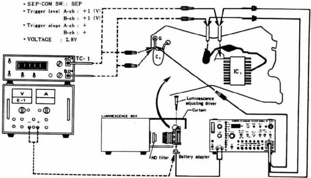
Body and measuring instrument setting
- Body
-
Make the adjustment by turning VR₂ so that counter indication is within the standard value (32\~36 ms) when shutter is released. Turning VR₂ clockwise increases shutter speed.
-
Change Luminescence box to EV 15 (ASA 100), detach ND filter and release shutter. Then make sure that shutter speed ranges from 0.95\~1.7 ms. (VR₄ should be shortcircuited). If shutter speed is out of the range, adjust VR₂ within the specification in 2.
4 Adjustment of VR3 -Indication adjustment-
■ Measuring instruments:
: Camera standard tester (ST-5101) or Constant voltage D.C power supply (Model E-1 or E-2)
: Luminescence box (L-222 or L-223)
: Standard lens (50 mm, F 1.4)
: Battery adapter (2006-0415-75)
• Luminescence adjusting driver-B
Standard value:
| (1) Luminescence : EV 11 ASA 100 (BV 6) | ||
| ASA sensitivity: 100 (SV 5) | ||
| F-number : F 8 (AV 6) | ||
| (2) Luminescence : EV 9 ASA 100 (BV 4) | ||
| ASA sensitivity: 100 (SV 5) | ||
| F-number : F 11 (AV 7) | ||
| (3) Luminescence : EV 14 ASA 100 (BV 9) | ||
| ASA sensitivity: 100 (SV 5) | ||
| F-number : 5.6 (AV 5) |
| -1 | -0.5 | 0 | +0.5 | +1 | EV | |
| 60 | ● | ● | ● | ● | ● | |
| 30 | ● | ● | ☀ | ● | ● | |
| 15 | ● | ● | ● | ● | ● | |
| 8 | ☀ | ☀ | ● | ● | ● | |
| 4 | ● | ☀ | ☀ | ☀ | ● | |
| 2 | ● | ● | ● | ☀ | ☀ | |
| 1000 | ☀ | ☀ | ● | ● | ● | |
| 500 | ● | ☀ | ☀ | ☀ | ● | |
| 250 | ● | ● | ● | ☀ | ☀ |
■ Adjustment procedure
Arrange measuring instrument, set power source voltage to 2.8V, shutter dial (A) and metering switch (S₁) to ON as illustrated below.
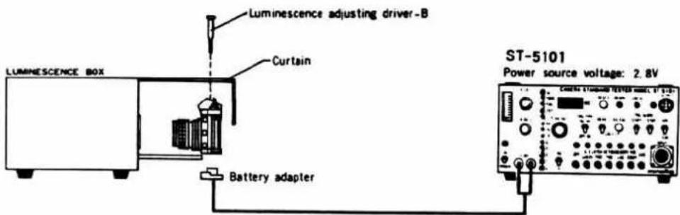
- When luminescece box=EV 11 (ASA 100) and standard lens=F 8:∞, LED for standard value (I) should light up. Make the adjustment by VR₃. Turning VR₃ clockwise shifts the indication upwards.
- When luminescence box-EV 9 (ASA 100) and standard lens-F 11; , LED for standard value (2) should light up. If the indication is out of the specification, check the indication for EV 14 (ASA 100) and then make the adjustment by the following method or
- When luminescence box-EV 14 (ASA 100) and standard lens-F5.6: , LED for standard value (3) should light up. If the indication is out of the specification, make the adjustment by the following method or
■ Adjustment of slope
If LED is deflected as shown in A, change resistor ( R_s ) to larger resistance.
If LED is deflected as shown in B, change resistor ( R_s ) to smaller resistance.
■ When R_s is replaced, make the adjustment from the initial step.
| 250 | ☀ | ||
| 125 | ☀ | 1000 | ☀ |
| 60 | |||
| 30 | · | 30 | ☀ |
| 15 | ☀ | 2 | ☀ |
| 8 | ☀ | 1 | ☀ |
| A | B | ||
■ Manual sec. time adjustment
※ This adjustment should be done after Auto exposure adjustment.
■ Measuring instruments:
: Camera standard tester (ST-5101) or Constant voltage D.C power supply (Model E-1 or E-2)
: Shutter tester (Model FS1D-MN4 or S-2101)
: Battery adapter (2006-0415-75)
Standard value:
| Shutter speed | Reference value | Allowable value |
| 1/30 | 31.3 ms | 30~33 ms |
| 1/1000 | 0.98 ms | 0.69~1.38 ms |
NOTE: Allowable value stands for the center value of shutter tester. As for unevenness, refer to Inspection Specification.
■ Adjustment procedure
- Arrange the measuring instrument and set the power source voltage to 2.8V as illustrated below.
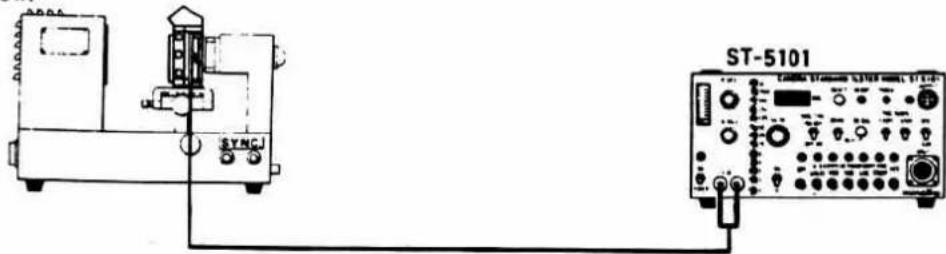
- Release shutter with shutter dial set at 1/30 and make the adjustment by VR₁ so that the measured value is proximate to reference value (31.3ms). Turning VR₁ clockwise decreases shutter speed.
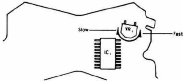
- Next, set shutter speed to 1/1000 and release shutter. Then make the adjustment by VR, so that the measured value is proximate to reference value (0.98 ms). Turning VR, clockwise increases shutter speed.
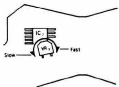
- Repeat the adjustments in (2) and (3).
- If manual sec. time is released or at high speeds, refer to the Trouble Shooting Chart. (Page. 16–17)
AUTO exposure checking
■ Measuring instruments:
: Camera standard tester (ST-5101) or Constant voltage D.C power supply (Model E-1 or E-2)
: Luminescence box (L-222 or L-223)
: EE tester (Model EE-2101 or EE-2111)
: Shutter tester (Model SD-2101)
: Standard lens (50 mm, F 1.4)
: Power source adapter
Standard value:
| Measuring luminance (ASA 100) | SD-2101 Aperture switch | Shutter speed allowable range (ms) | EE level allowable range (EV) | EE level variation (EV) |
| EV15 | F 5.6 | 0.58~1.71 | ±0.8 EV | Within 0.6 EV |
| EV14 | 1.12~3.40 | |||
| EV 9 | 35.8~109 |
NOTE: When EE level measurement with luminescence EV 15 (ASA 100) causes over-range mark to light up, shutter is not released. At that time, it is normal if EE level requirement EV 14\~EV 9 is satisfied.
■ Checking procedure
- Arrange the measuring instrument as illustrated below.
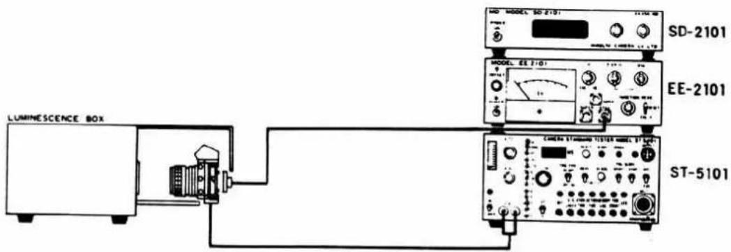
Body and measuring instrument setting
- Body
| • Luminescence change SW.: Same as luminescence box |
| • Diaphragm change SW.: F 5.6 |
- Release shutter and make sure that shutter speed and EE level are within the standardvalue.
• If shutter speed and EE level are out of the standardvalue, make the adjustment of AUTO exposure.
Indicating LED checking and adjustment
■ Measuring instruments:
: Camera standard tester (ST-5101)
: Battery adapter (2006-0415-75)
■ Checking procedure
- Disconnect two leads (green, blue) of CdS board and connect the lead wires to measuring instrument, and then set the camera on the measuring instrument as illustrated.
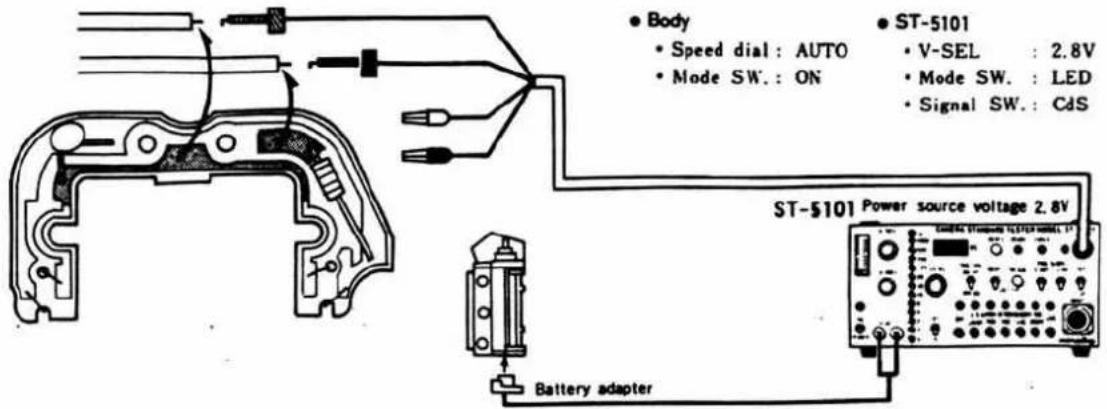
- Set metering switch (S₁) to ON and turn ASA dial so that LED continuously lights up from ▽ (under-range warning) to △ (over-range warning).
- Look into finder and make sure that indication is clear without vignetting of LED from to .
- If vignetting of LED exists in the view, make the adjustment according to the following procedure.
■ Adjustment procedure
- With the above lead connections, loosen set-screws of LED board and shift it in the direction of arrow as illustrated. Tighten the set-screws when the indication is evenly clear and brightest from ▽ to △.
- When the adjustment is impossible, the position of on pentagon holder side is defective. Refer to the Assembly Chart. (Page.19)
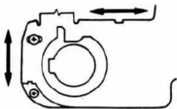
natural_image
Pure mechanical component diagram without any text, numbers, or symbols■ Touch switch operation checking
■ Measuring instruments:
: Camera standard tester (ST-5101) or Constant voltage D.C power supply (Model E-1 or E-2) : Battery adapter (2006-0415-75)
Standard value:
Indication is on with 10 MΩ, and off with 30 MΩ.
■ Checking procedure
- Arrange measuring instrument as illustrated. Set shutter dial to (A) and power source voltage to 2.8V.
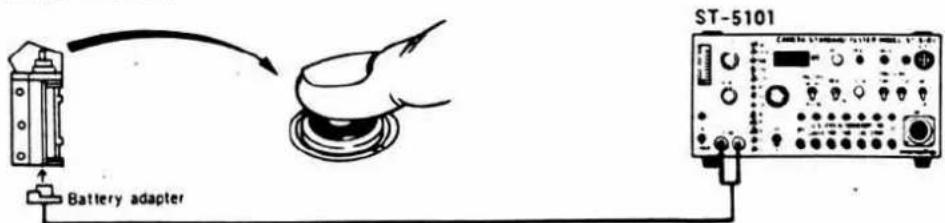
- Touch the switch (not pressing) and make sure that indication lights up.
• If it doesn't light up, moisten the finger.
- If it still doesn't light up, push shutter button until metering switch (S₁) is activated. At that time, if indication lights up, touch switch and S₁ contact are defective and if it doesn't light up, refer to the Trouble Shooting Chart. (Page. 13)
Over-range lock checking
■ Measuring instruments:
: Camera standard tester (ST-5101) or Constant voltage D.C power supply (Model E-1 or E-2) : Luminescence box (L-222 or L-223) : Battery adapter (2006-0415-17)
Standard value:
1) Luminescence : EV 15 (ASA 100) (BV 10) ASA sensitivity : 250 (SV 6.25) F-number : F 5.6 (AV 5) 2) Luminescence : EV 14 (ASA 100) (BV 9) ASA sensitivity : 125 (SV 5.25) F-number : F 5.6 (AV 5) Releasing should be impossible with △ (over-range) lighted. Releasing should be possible with ▲ (over-range) off.
■ Checking procedure
- Arrange the measuring instrument and set the power source voltage to 2.8V and shutter dial to (A).
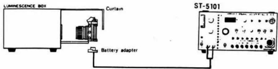
- When luminescence box = EV 15 (ASA 100), standard lens = F 5.6; , and ASA sensitivity = 250, releasing should be impossible with (over-range) lighted.
- When luminescence box = EV 14 (ASA 100), standard lens = F 5.6; , and ASA sensitivity = 125, releasing should be possible with (over-range) off.
- If the above requirements are not satisfied, the adjustment of VR 3 (indication adjustment) is wrong. Refer to the adjustment of VR 3 . (Page. 33)
■ Magnetic release minimum operation voltage and release lock voltage checking
■ Measuring instruments:
: Camera standard tester (ST-5101) or Constant voltage D.C power supply (Model E-1 or E-2) : Battery adapter
Standard value:
Shutter should not operate at 1.75V but at 2.15V.
■ Checking procedure
- Arrange the measuring instrument as illustrated below and set power source voltage to 1.75V. At that time, shutter should not become released.
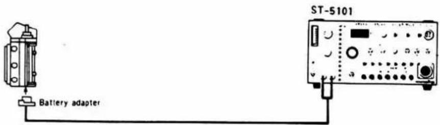
- With the connections kept as they are, set power source voltage to 2.15V, once set body mode switch to OFF and again to ON.
Subsequent shutter releasing should be possible.
- When shutter releasing is impossible with power source voltage set at 2.15V, and C_6 (100 μF) as illustrated below and do checking as in 2.
If shutter is not released with C_6 added, or if shutter releasing is possible at 1.75V, release magnet (Mg.2) or circuit board is defective, repair it with reference to Trouble Shooting Chart. (Page.15)
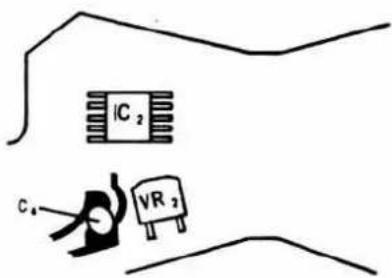
B. C lamp lighting voltage checking
■Measuring instruments:
: Camera standard tester (ST-5101) or Constant voltage power supply (Model E-1 or E-2) : Battery adapter (2006-0415-75)
Standard value:
Lamp is off at 1.85V, and on at 2.15V (at 25°C room temperature)
■ Checking procedure
Arrange the measuring instrument as illustrated below. Set power source voltage to 1.85V, and B.C switch to ON (in the direction of arrow). Then make sure the lamp is off. Similarly, set power source voltage to 2.15V, then make sure B.C lamp is lighted.
- If B.C lamp doesn't turn on, refer to Trouble Shooting Chart. (Page. 11)
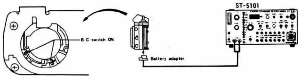
Indicating LED minimum lighting voltage checking
■ Measuring instruments:
: Camera standard tester (ST-5101) or Constant voltage power supply (Model E-1 or E-2) : Battery adapter (2006-0415-75)
Standard value:
LED should light up at 2.0V in darkness.
■ Checking procedure
Arrange the measuring instrument as illustrated below. Set power source voltage to 2.0V, shutter dial to (A), and release switch (S₁) to ON, with light shielded, indicating LED (V) should then light up.
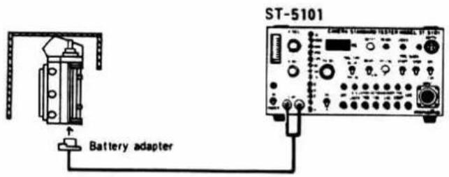
Self-timer operation checking
■ Measuring instruments:
: Camera standard tester (ST-5101) or Constant voltage D.C power supply (Model E-1 or E-2) : Battery adapter (2006-0415-75)
Standard value:
After releasing shutter button, self-timer lamp should start blinking within 1 sec., and blinking cycle should change before releasing. Shutter should be released in 6\~15 sec. after releasing shutter button.
■ Measuring procedure
Arrange the measuring instrument as illustrated below. Set power source voltage to 2.8V, mode switch to "SELF TIMER" and shutter dial to MANUAL (except B), the specification should be satisfied.
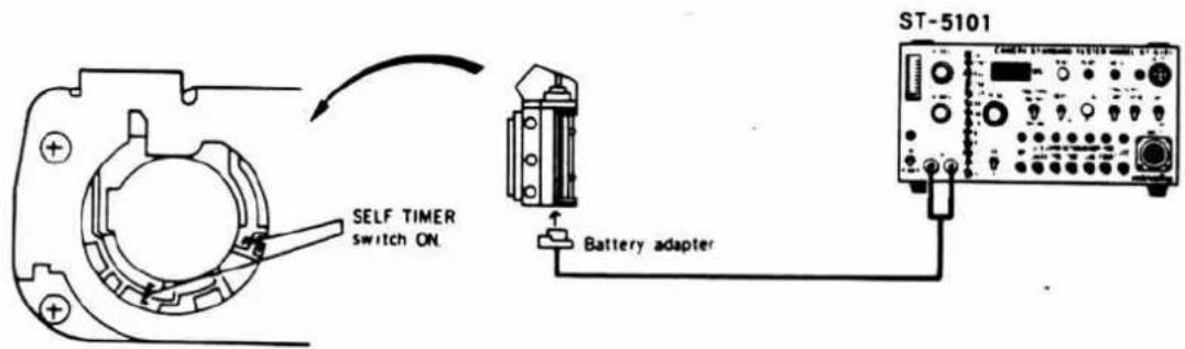
- If self-timer fails to operate, refer to Trouble Shooting Chart (Page.18)
If self-timer operates but shutter is not released, refer to Trouble Shooting Chart (Page. 18)
■ Minimum operation voltage checking
■ Measuring instruments:
: Camera standard tester (ST-5101) or Constant voltage D.C power supply (Model E-1 or E-2)
: Shutter tester (Model FS1D-MN4 or S-2101)
: Battery adapter (2006-0415-75)
Standard value:
With voltage at 2.25V and 2.8V, shutter speed 1/1000 should be 0.69\~1.38 ms. (2.15V____0.60\~1.45 ms)
■ Checking procedure
Arrange the measuring instrument as illustrated below. Set shutter dial to (1/1000), and release the shutter at 2.8V and 2.25V respectively, thus measure the shutter speeds. At that time, make sure that shutter speeds are within the specification (0.69\~1.38 ms).
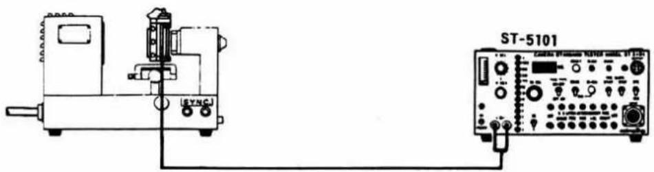
- If the measured speeds are out of the standard value, re-adjust shutter speed or check shutter. (Refer to Page. 49)
■ Synchro time lag checking
■ Measuring instruments:
: Camera standard tester (ST-5101) or Constant voltage power supply (Model E-1 or E-2)
: Shutter tester (Model FS1D-MN4 or S-2101)
: Battery adapter (2006-0415-75)
Standard value:
| Shutter speed | 1/60 |
| Range A | 0.3 ms or over |
| Range B | 2 ms or over |
■ Checking procedure
Arrange the measuring instrument as illustrated. Set shutter speed to 1/60, shutter tester to "FUNCTION", power source voltage to 2.8V.
Then release the shutter and make sure the measured value is within the standard value.
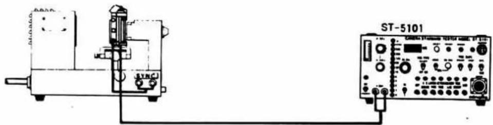
- When the measured value is out of the standard value, check and adjust the shutter. (Refer to Page. 51)
Strobe function checking
① Checks before completion of charge
■ Measuring instruments:
: Camera standard tester (ST-5101) or Constant voltage D.C power supply (Model E-1 or E-2)
Standard value:
| Voltage (V) | Indication in finder | Release shutter |
| 0 | AUTO speed | Operation at speed matched with AUTO speed. |
| 1.6 | Indication is off. | Shutter is released. 2nd curtain runs with power off. |
| 2.0 | “60” LED is on. | Shutter is released. 2nd curtain runs with power off. |
■ Checking procedure
- Arrange the measuring instrument as illustrated below. Set shutter dial to (A) and power source voltage to 0\~2.0V, then check the measured value. (Battery is to be used for power supply to the camera.)
- If the operation is wrong, refer to Trouble Shooting Chart (Page. 19).
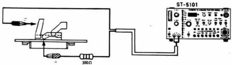
② Checks on completion of charge
■ Measuring instruments:
: Camera standard tester (ST-5101) or Constant voltage D.C power supply (Model E-1 or E-2)
: Shutter tester (Model FS1D-MN4 or S-2101)
: Exclusive strobo (8668)
: Battery adapter (2006-0415-75)
Standard value:
"60" LED should blink on completion of strobo charge. Shutter speed should change to 20 ms (17\~23 ms)
■ Checking procedure
- Mount exclusive strobo (8668) on camera, set shutter speed to (A) and metering switch (S_1) to ON to charge the strobo.
Auto speed should be indicated until completion of charge, and "60" LED should blink while the other indications are off on completion of charge (Ne tube is on).
- Arrange the measuring instruments as illustrated right. Set shutter speed to 1/1000 and release shutter on completion of strobo charge, then make sure the measured value is within the specification (17\~23 ms). (Light should be shut out to prevent shutter tester from the light of strobo.)
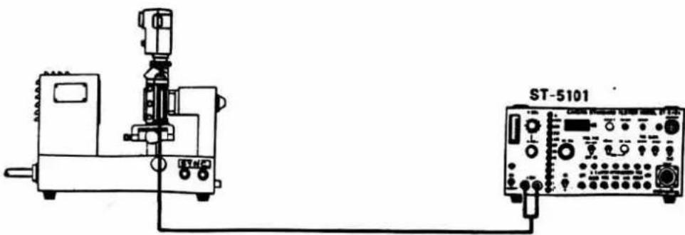
natural_image
Technical line drawing of a mechanical device connected to an oscilloscope (no text or symbols visible)- If strobo doesn't operate properly, do the checks before completion of charge. If the results of above checks are satisfactory, the connector contact or strobo (8668) are defective. (Refer to the instructions for strobo.)
Body back (B. B) adjustment
■ Measuring instruments:
: Body back adjusting standard gauge (43.70 mm)
: Parallel soureface flat plate (for 2005)
: Dial gauge
: Battery
: Temporary nuts (2006-3309-75)
Standard valve
43.70±0.01mm
■ Adjustment procedure
- Adjustment of pressure plate contacts.
Place parallel sourface flat plate on body pressure plate contacts and lightly push the arrow-marked part with fingers to check for clearance.
Adjust the level by tapping the place using a fiber cushion.
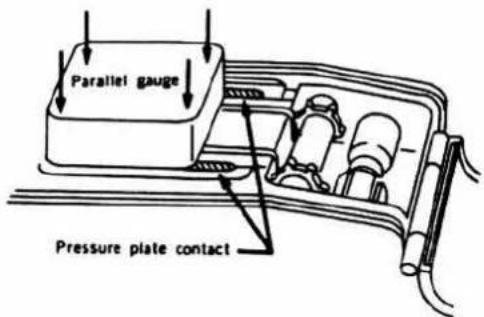
- Body back measurement
Set shutter dial to "B" and self-timer change contact holder to "ON" then release the shutter and put parallel gauge on pressure plate contact. Check zero position of dial gauge, using standard gauge. Slide the dial gauge up and down, right and left, and diagonally, then measure body back.
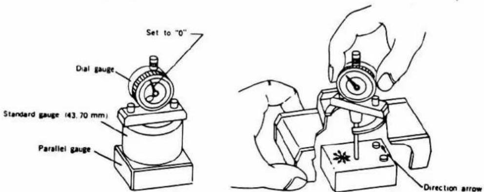
- Body back adjustment
When measured value is lower than specification;
adjust it by 4 types of washer for adjustment.
Refer to the following table:
| Type | 2005-1061-81 | 2005-1062-81 | 2005-1063-81 |
| Thickness (mm) | 0.02 | 0.05 | 0.1 |
When measured value is higher than specification;
replace with bayonet lens mount (2005-1010-81) and also make the adjustment with use of adjusting washers.
■If body is greatly deviated, check for cracks in front plate and body.
Finder back adjustment
■ Measuring instruments:
: 1000 mm collimator (Medel RC-1000 I. II. III)
: Master lens for 054 finder-back adjustment (054-5202-79)
: Magnifier (8213-007)
Standard value: 43.56±0.025 mm
■ Adjustment procedure
- Place the body in such a position that chart image is visible as illustrated below. Set the magnigier visibility to the chart image.
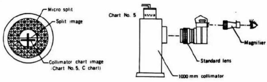
- With white line of standard lens matched, evenly move pint adjust screw up and down, when vertical line of chart image has become matched, lock the screw.
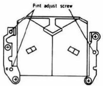
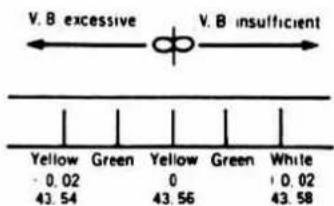
- After adjustment, operate mirror several times, rotate helicoid of standard lens, and when vertical line of chart image has become matched, check that the value is within the standard value (43.56±0.025 mm) without one-side vignette.
When standard lens is matched with white line


Adjust screw should be evenly turned.
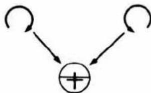
flowchart
graph TD
    A[" "] --> C["+"]
    B[" "] --> C["+"]
Adjust screw turning direction
Top cover assembly
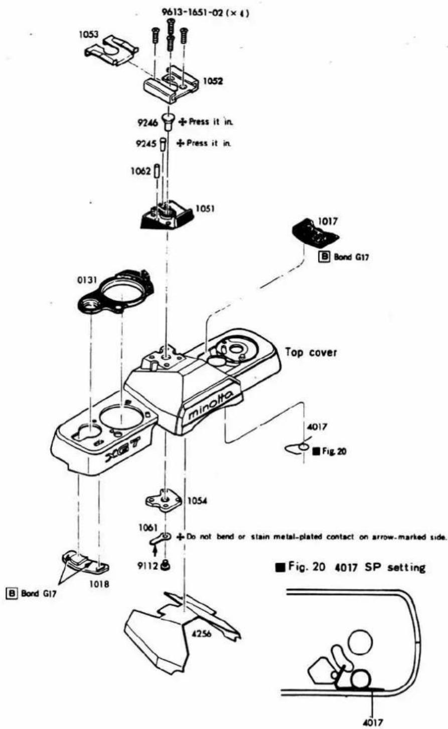
15 Top cover Bottom cover Outer finish
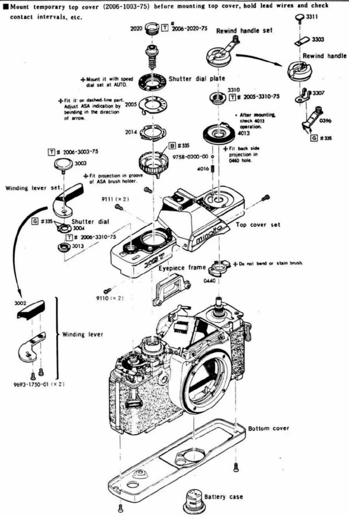
Shutter performance checking
■ Checking items
- Magnetic attraction and magnetic piece over-range volume.
- Curtain speed.
- Manual sec. time.
- Minimum operation voltage.
- Curtain bound.
- Synchro time lag.
■ When checking before mounting body:
- Shift winding bearing (0310) of body for shutter block adjustment (2006-0101-75) in the direction of arrow, and set eccentric screw (9281) of shutter charge gear D (0350) in the position as illustrated below.
- Mount shutter block on front frame of adjusting body and shift front frame towards body winding side.
- Shift winding bearing (0310) in the direction opposite to the arrow so that (−) of charge gear A (2105) is engaged with shutter charge gear C (3016) as illustrated below. Then tighten up set-screws.
- When winding is slowly done to greatly move 2nd curtain stop lever (0219) in the direction of arrow. Make the adjustment so that sprocket idle gear (3034) is over-charged by 1 tooth from control base plate (0202) thus completing winding after shutter charge completion. Carry out checking in the above order.
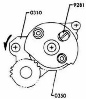
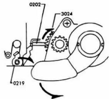
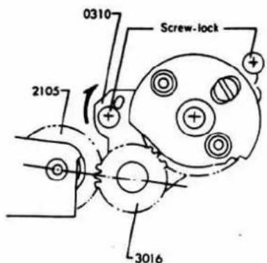
■ When checking after completion of body:
- Remove top cover, and mount winding lever and shutter dial section.
- Disconnect shutter control magnet + side (red), - side (brown), trigger switch + side (violet), - side (black) lead wires from flexible circuit board.
- Load the batter box with battery (to operate release magnet).
- Set shutter dial to other point than AUTO (to prevent release locking).
Carry out checking in the above order.
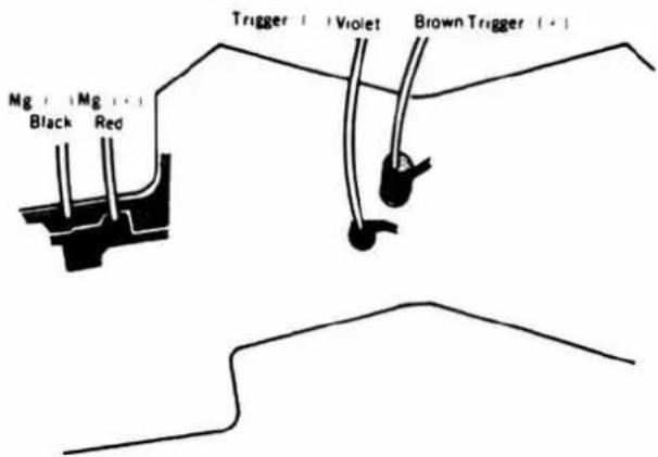
■ Precautions for measurement
If high speed operation or speed change occurs when the shutter connected to the measuring instrument is released, release the shutter with the MEAS-CAL switch set to either "CAL" or "MEAS".
① Magnetic attraction and magnetic piece over-range volume checking
■ Measuring instrument: Camera standard tester (ST-5101)
Standard value: No high speed operation at 1.5V.
-
Connect the measuring instrument and shutter as illustrated below. Make the setting of the tester as follows.
-
High speed operation should not result when shutter is released.
• If high speed operation results, refer to Shutter performance adjustment.
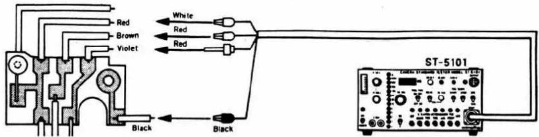
ST-5101
V-SEL: 1.5V MEAS-CAL: MEAS SS-SEL: 1 sec Mode-SW.: SS CHECK SS-X: SS TRIG TYPE ON-OFF, OFF-ON: ON-OFF
② Curtain speed checking
■ Measuring instruments:
: Camera standard tester (ST-5101) : Shutter tester (Model FS1D-MN4 or S-2101)
Standard valve: 11.0±0.2 ms (standard value) and 13 ms or less (allowable value) for both 1st and 2nd curtains.
- Connect the measuring instrument and shutter block as illustrated below. Make the setting of the tester as follows.
- When shutter is released, both curtain speeds should be same within the specification.
• If the speeds are out of specification, refer to Shutter performance.
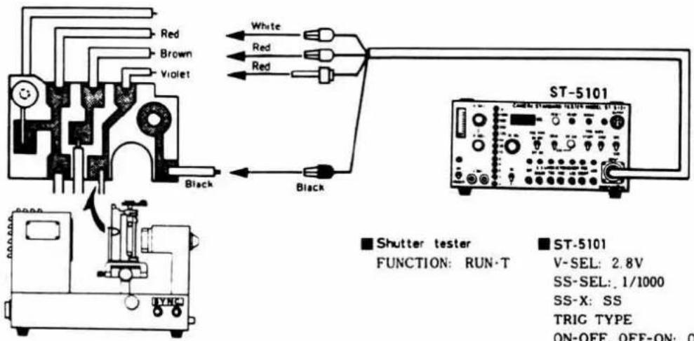
Shutter tester
FUNCTION: RUN-T
ST-5101
V-SEL: 2.8V SS-SEL: 1/1000 SS-X: SS TRIG TYPE ON-OFF, OFF-ON: ON-OFF MEAS-CAL: MEAS Mode-SW.: SS CHECK
③ Manual sec. time checking
■ Measuring instruments:
: Camera standard tester (ST-5101)
: Shutter tester (Model FS1D-MN4 or S-2101)
Standard value:
| Shutter speed | Standard | Allowable | |
| 1/1000 | 0.98 ms | 0.7~1.34 ms | ±0.45 EV |
| 1/30 | 31.3 ms | 26.3~37.2 ms | ±0.25 EV |
| 1/1 | 1000 ms | 841~1190 ms | |
- Connect the measuring instrument and shutter block as illustrated below. Make the setting of the tester as follows.
- When shutter is released at each speed with SS-SEL switch of camera standard tester set 1/1000, 1/30 and 1/1, the indication of shutter tester should be within the specification.
• If the results are out of the specification, refer to Shutter performance adjustment.
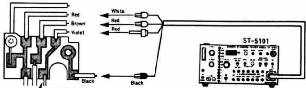
■ Shutter tester
FUNCTION: EXP.T
■ ST-5101
V-SEL: 2.8V
SS-SEL: 1/1000, 1/30, 1 sec
SS-X: SS
TRIG TYPE ON-OFF, OFF-ON: ON-OFF MEAS-CAL: MEAS Mode-SW.: SS CHECK
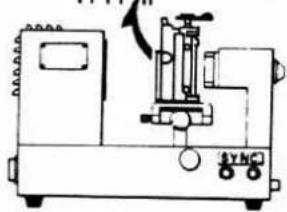
natural_image
Technical line drawing of a mechanical device with no visible text or symbols4 Minimum operation voltage checking
■ Measuring instruments:
: Camera standard tester (ST-5101)
Standard value: Difference in shutter speed between power source voltages 2.8V and 1.85V should be within 0.4 ms.
- Connect the measuring instrument and shutter block as illustrated right. Make setting of the tester as follows.
- Set V-SEL switch of camera standard tester to 2.8V, release the shutter and read the indication of shutter tester.
- Next, set the V-SEL switch to 1.85V, release the shutter. Then, difference between the indication and the reading in 2 should be within 0.4 ms.
• If the results are out of the specification, refer to shutter performance adjustment.
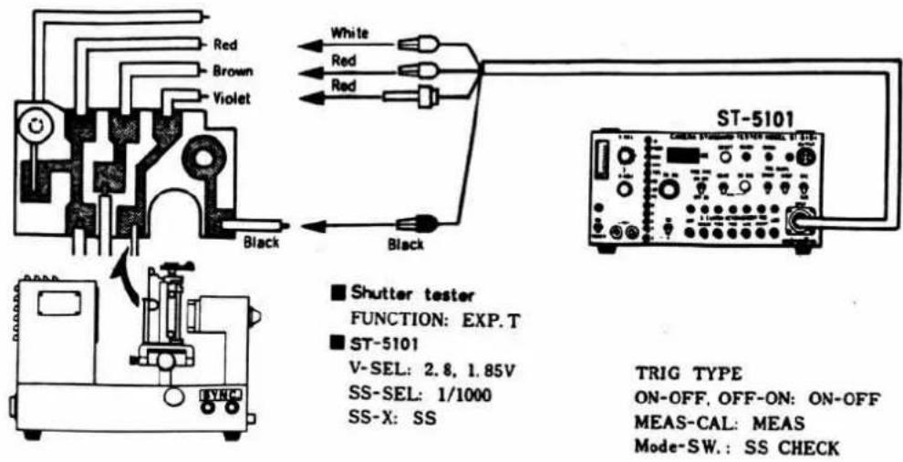
5 Curtain bound checking
■ Measuring instruments:
: Camera standard tester (ST-5101)
: Shutter tester (Model FS1D-MN4 or S-2101)
Standard value: No bound in the view.
- Connect the measuring instrument and shutter block as illustrated below. Make the setting of tester as follows.
- When shutter is released, no bound should be observed.
• If any bound is observed, refer to shutter performance adjustment.
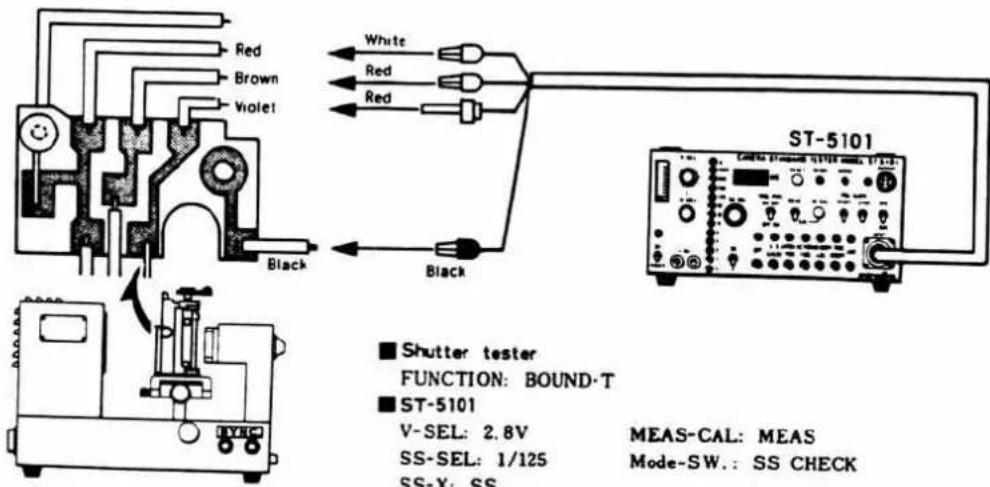
■ Shutter tester
FUNCTION: BOUND·T
ST-5101
V-SEL: 2.8V
SS-SEL: 1/125
SS-X: SS
TRIG TYPE
ON-OFF, OFF-ON: ON-OFF
MEAS-CAL: MEAS
Mode-SW.: SS CHECK
⑥ Synchro time lag checking
■ Measuring instruments:
: Camera standard tester (ST-5101)
: Shutter tester (Model FS1D-MN4 or S-2101)
Standard value:
| Shutter speed | Allowable time lag | |
| 1/60 | Range A | 0.3 ms or over |
| Range B | 2.0 ms or over | |
- Connect the measuring instrument and shutter block as illustrated below. Make the setting of tester as follows. When checking complete body shutter block, connect synchro terminal ans shutter tester.
- When shutter is released, indications in ranges A and B should be within the specification.
- If the results are out of the specification, refer to Shutter performance adjustment.
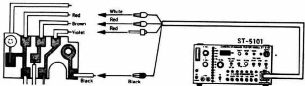
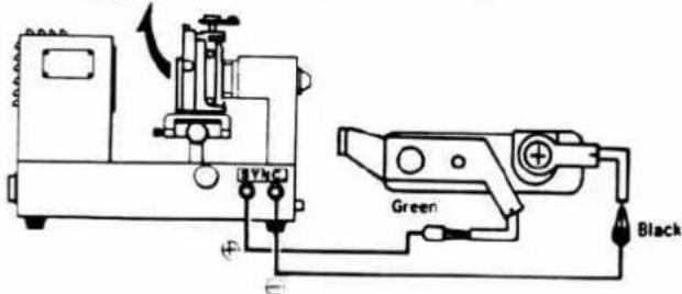
■ Shutter tester
FUNCTION: X
■ST-5101
V-SEL: 2.8V
SS-SEL: 1/60
SS-X: SS
TRIG TYPE
ON-OFF, OFF-ON: ON-OFF
MEAS-CAL: MEAS
Mode-SW: SS CHECK
Trouble Shooting Chart
I. Hints on use of Trouble Shooting Chart
- This chart includes the symptoms and causes of troubles on the camera side.
- Even when a symptom appears on the camera side, the trouble is not always on the camera side but in connection with the replacement lens, winder or exclusive strobo. Therefore, carefully check operations related to the auxiliary parts before using this chart.
2. Contents of Chart
- Mentioned in this chart are only individual patterns and these cannot cover all possible causes.
Regarding multiple causes, carry out an all-round investigation of the trouble. - The chart mainly covers electrical causes and to a certain extent mechanical causes.
3. Precautions for Work
- A digital tester (2507) is to be used as the measuring instrument. It is also allowable to use other measuring instruments when the input impedance exceeds 10 MΩ.
- Use the measuring instrument to check voltages, and a tester of less than 3V to check current conduction.
- It can be safely said that troubles of electric parts such as IC's diodes, transistors, resistors, capacitors, etc. seldom occur. It is therefore practical to put emphasis on checking for defective soldering of lead wires and electric parts, defective switches, etc.
- When checking for defective soldering, do not excessively press the parts or pull the lead wires.
- When measuring voltage, attach a pin to the end of alligator clip because the portion measured is very narrow. Do not directly connect the alligator clip with the portion measured; otherwise damage to the electric parts or to the pattern may occur.
- When measuring the switch operation pattern, take care not to scratch the pattern outside the switch operation range. In case of a switch contact, take care not to disturb the switch contact.
- When removing electric parts, pull out the power supply cord.
- The desirable soldering iron temperature is about 260\~300°C. In any case, finish soldering in a few seconds. Be sure to remove chips before soldering.
4. How to use the Trouble Shooting Chart
-
The chart includes check points in detail ranging from the appearance of symptoms to the finding of causes.
-
The flexible circuit board should be normal.
-
The voltage at each check point is to be the normal voltage when SW.1 and SW.7 are set to ON with winding completed (before releasing), 3.0V power supply (constant voltage), and 1/30 AUTO.
-
The earth is not connected to the body, check the earth on the flexible circuit board.
-
The indications in the Trouble Shooting Chart are Symptom, (Symptom to be checked), Check point, Normal voltage at check point, Defective voltage, Possible cause, Probable cause, and the marks in circles stand for check points in the flexible circuit board and circuit diagram.
5. Battery capacity checking method
-
Connect the 100Ω resistor to the battery as illustrated. Also, connect a digital tester or voltmeter in parallel with the resistor and then measure the voltage. The measurement should be done in a short time to avoid excessive consumption of battery power.
-
The battery is normal if the measured voltage is over 1.4V.
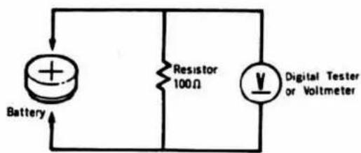
- List of troubles due to defective IC contacts
| Auto | Manual | Bulb | B. C | ||||||
| Indication | Release | Shutter speed | Self timer | Release | Shutter speed | Self timer | |||
| IC-1 1 | at all time (Occasionally-normal) | No | Not start | Yes | Unstable | Normal | Yes | Normal | |
| 2 | at all time | No | Not start | Yes | Curtain runs without slit | Normal | Yes | Normal | |
| 3 | at all time | No | Not start | Yes | Curtain runs without slit | Normal | Yes | Normal | |
| 4 | No lighted | Yes | Kept open | Normal | Yes | Kept open | Normal | Yes | Normal |
| 5 | Normal | Yes | Curtain runs without slit | Normal | Yes | Curtain runs without slit | Normal | Yes | Normal |
| 6 | Low on the whole | Yes | Faster shutter speed than indication | Normal | Yes | Normal | Normal | Yes | Normal |
| 7 | at all time | No | Not start | Yes | Normal | Normal | Yes | Normal | |
| 8 | Normal (*1) | Yes | Normal (*2) | Normal | Yer | Normal (*2) | Normal | Yes | Normal |
| 9 | Normal | No | Not start | No | Not start | No | Normal | ||
| 10 | Normal | Yes | Short or curtain runs without slit | Normal | Yes | Short or curtain runs without slit | Normal | Yes | Normal |
| 11 | Normal | Yes | Curtain runs without slit | Normal | Yes | Curtain runs without slit | Normal | Yes | Normal |
| 12 | Normal | Yes | Long sec. at all time | Normal | Yes | Long sec. at all time | Normal | Yes | Normal |
| 13 | Normal (*1) | Yes | Normal | Normal | Yes | Normal | Normal | Yes | Normal |
| 14 | at all time | No | Not start | No | Not start | No | Normal | ||
| 15 | Normal | Yes | Curtain runs without slit | Normal | Yes | Curtain runs without slit | Normal | Curtain runs without slit | Normal |
| 16 | Normal | Yes | Curtain runs without slit | Normal | Yes | Curtain runs without slit | Normal | Curtain runs without slit | Normal |
| 17 | No lighted | Yes | Kept open | Normal | Yes | Kept open | Normal | Yes | Normal |
| 18 | No change | Yes | No change | Normal | Yes | No change | Normal | Yes | Normal |
| 19 | Run | Yes | Curtain runs without slit | Normal | Yes | Curtain runs without slit | Normal | Yes | Normal |
| 20 | No lighted | Yes | Kept open | Normal | Yes | Kept open | Normal | Yes | Normal |
※ 1 : No indication with exclusive strobo.
※ 2 : Shutter speed doesn't change to 1/60 sec. with exclusive strobo.
| Auto | Manual | Bulb | B. C | ||||||
| Indication | Release | Shutter speed | Self timer | Release | Shutter speed | Self timer | |||
| IC-3 1 | Normal | No | Not start | No | Not start | No | Normal | ||
| 2 | Normal | Yes | Blub | Normal with shutter button pushed | Yes | Blub | Normal with shutter button pushed | Yes | Normal |
| 3 | Normal | Yes | Normal | Normal (※3) | Yes | Normal | Normal (※3) | Yes | Normal |
| 4 | Normal | Yes | Normal | LED not blinking | Yes | Normal | LED not blinking | Yes | Normal |
| 5 | Normal | Yes | Normal | No tightened | Yes | Normal | No lighted | Yes | No lighted |
| 6 | Normal | Yes | Normal | No delay time | Yes | Normal | No delay time | Yes | Normal |
| 7 | Normal | Yes | Normal | No delay time even with °° | Yes | Normal | No delay time | Yes | Normal |
| 8 | Normal | No | Only indication (about 10 sec.) | No | Only indication | No | Normal | ||
| 9 | Normal | Yes | Normal | Normal | Yes | Normal | Normal | Yes | No lighted |
| 10 | Normal | No | No indication (Available shutter release) | No | No indication (Available shutter release) | No | Normal | ||
| IC-4 1 | No lighted | Yes | Kept open | Only blinking | Yes | Kept open | Normal | Yes | Normal |
| 2 | No lighted | No | Not start | No | Not start | No | Normal | ||
| 3 | No lighted | Yes | Kept open | Normal | Yes | Kept open | Normal | Yes | Normal |
| 4 | Normal | No | Not start | No | Not start | No | Normal | ||
| 5 | Normal | No | Not start | No | Not start | No | Normal | ||
| 6 | Normal | No | Not start | No | Not start | No | Normal | ||
| 7 | Normal | No | Only indication | No | Only indication | No | Normal | ||
| 8 | Normal | No | Only indication | No | Only indication | No | Normal | ||
| 9 | Normal | No | Only indication | No | Only indication | No | Normal | ||
| (※4) 10 | Normal | Yes | Normal | Normal | Yes | Normal | Normal | Yes | Normal |
| 11 | Normal | Yes | Curtain runs without slit | Normal | Yes | Curtain runs without slit | Normal | Curtain runs without slit | Normal |
| 12 | No lighted | Yes | Kept open | Normal | Yes | Kept open | Normal | Yes | Normal |
* 3 : Blinking only when battery capacity is low.
* 4 : Auto winder doesn't operate.
- List of troubles due to electrical parts and switches
| Defective contacts | Shortcircuit troubles | |
| C_1 | Both AUTO and MANUAL ...released. (curtain is kept open) | Both AUTO and MANUAL...released. (curtain is kept open) |
| C_2 | Both AUTO and MANUAL...high speed. (curtain doesn't open) | Both AUTO and MANUAL...released. (curtain is kept open) |
| C_3 | Variation occurs due to shutter operation at high speeds. | Both AUTO and MANUAL...high speed. (curtain doesn't open) |
| C_4 | Self-timer turns off without blinking. | Self-timer turns off without lighting. |
| C_5 | Self-timer doesn't work. | Shutter lock and self-timer do not operate in auto and manual. |
| C_6 | Magnetic release doesn't operate. | Magnetic release doesn't operate. |
| C_7 | Metering circuit oscillates and indication unstable. | Both AUTO and MANUAL...released. (curtain is kept open) |
| C_8 | Self-timer blinks but doesn't turn off. Long sec. time is elongated. | Shortcircuit occurs during metering indication, and battery is exhausted too quickly. |
| VR_1 | MANUAL released. (curtain is kept open) | MANUAL...high speed. (curtain doesn't open) |
| VR_2 | ^* ^* lights up at all times in Auto. It cannot be adjusted. | Auto sec. time is long and cannot be adjusted. |
| VR_3 | ^* ^* lights up at all times in Auto. | Auto indication is set to low speed side, and sec. time is not affected. |
| VR_4 | AUTO and MANUAL...high speed. | Sec. time is long at high speed. |
| R_1 | EE linearity change great. | No low speed sec. time. |
| R_2 | Auto released. (curtain is kept open) | Auto high speed sec. time tends to become long. |
| R_3 | Both AUTO and MANUAL...released. (curtain is kept open) | Sec. time is long on the whole. |
| R_4 | Due to 180mV deflection, manual linearity and ASA changeover defective. | Sec. time is short on the whole. |
| R_5 | Shutter lock level unstable when battery capacity low. | Shutter lock level becomes high. |
| R_6 | Self-timer doesn't turn off while lighted. | Self-timer doesn't work. |
| R_7 | BC, self-timer not lighted. | LD 13 is too bright. |
| R_8 | Over-range indication deflected upwards and under- range indication downwards. | Over-range indication deflected downwards and under- range indication upwards. |
| R_9 | Indicating LED doesn't light up. | Indicating LED is too bright. |
| R_10 | BC, lighting voltage and shutter lock level sometimes inversed. | Shortcircuit lamp doesn't light up at BC. |
| TR | Even when ^* ^* is lighted, shutter is operated as release button is released. | Magnetic release doesn't operate. Self-timer doesn't operate. |
| Operation | Kept at ON | Kept at OFF | |
| S_1 | Metering SW. | Indication stays lighted. | Indication doesn't light up. |
| S_2 | Release SW. | Shutter is operated with winding lever shifted back. | Self, magnetic release do not operate. |
| S_3 | Trigger SW. | AUTO, MANUAL released. | AUTO & MANUAL...high speed(high SS, excessive variation) |
| S_4 | Reset SW. | Magnetic release doesn't operate. | Magnetic release doesn't operate. |
| S_5 | Bulb SW. | No Bulb (B). | AUTO & MANUAL...B at all times. |
| S_6 | B.C SW. | BC lighted at all times. | B.C doesn't light up. |
| Self SW. | Self is activated at all times. | Self doesn't work. | |
| S_7 | Main SW. | No operation at all. | |
| S_8 | AM SW. | AUTO released (at AUTO), MANUAL release (at MAN.) | |
| S_9 | TV SW. | MANUAL released. | |
| S_9' | SV SW. | AUTO released. | |
| S_10 | AV SW. | Shutter lock at AUTO, high speed at MAN. | |
| S_11 | Touch SW. | Indication stays lighted.(ON with below 10 MΩ) | Indication doesn't light up.(OFF with over 30 MΩ) |
8. Voltage at main check points of electric circuits
Power source voltage: 3 volts Camera condition: Auto
| Winding completed S4ON | During metering S1ON | During exposure S2ON | Exposure completed S1, S2ON | Remarks | |
| IC-11 | F | 2.95 | Power source (+) of metering and calculating circuit. | ||
| 2 | F | 0.75 | Output of metering circuit | ||
| 3 | F | 1.2 | 0.1 | 1.2 | Related to IC-1 ② |
| 4 | F | 2.8 | Power source for memory, indication level. | ||
| 5 | F | 1.25 | 0.1 | 1.25 | Output to memory condenser |
| 6 | F | 1.25 | 0.1 | 1.25 | Output to indication circuit |
| 7 | F | 1.25 | To IC-2 ⑦ | ||
| 8 | F | Input of strobo auto signal | |||
| 9 | F | 0 | 0.1 | 0.7 | Related to S2 |
| 10 | 0 | 1.3 | F | Related to S3 | |
| 11 | F | 3→2.2→0 | F | Charging voltage of C2 | |
| 12 | F | 0.6 | 0.1 | 0.6 | Memory voltage |
| * a13 | F | *0.8(1.7) | F | *0.8(1.7) | Related to blinking of LED "60" |
| 14 | 0 | Power source (-) of IC-1 | |||
| 15 | 3.0 | 0.1 | 3.0 | Output to 2 nd curtain control Mg. | |
| 16 | F | 2.95 | F | Power source (+) of control circuit | |
| 17 | F | 2.8 | Input of photo tube changer | ||
| *b18 | F | 0.7(0.55) | Power source (-) of calculating circuit | ||
| *c19 | F | 0.9(0.75) | Power source (+) of calculating circuit | ||
| *d20 | F | 0.8(0.65) | Related to TV information S, | ||
F→no voltage indication (indicated value is unstable.)
Parenthesized in *a, b, c, d are voltages at manual 1/30.
*-marked in *a are 0.2V with LED "60" lighted.
*e. f. g are as figures when self-timer is operated.
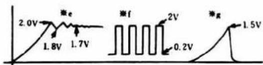
line
| Voltage (V) | Label | |-------------|-------| | 2.0 | e | | 1.8 | 1.8V | | 1.7 | 1.7V | | 2V | f | | 0.2 | 0.2V | | 1.5 | g || Winding completedS,ON | During meteringS1 ON | During exposureS2 ON | Exposure completedS1. S2 ON | Remarks | |
| IC-31 | F | 2.95 | F | Power source (+) of released circuit. | |
| 2 | 3 | 2.95 | 0.2 | 0.7 | Related to power source self-maintenance and to SS. |
| 3 | F | 0.7 | F | Related to release lock | |
| *e4 | F | Related to oscillator circuit for self-timer. | |||
| *f5 | F | 1.6 | LED blinking signal output for BC,self-timer. | ||
| *g6 | F | 1.1 | F | Switched to self-timer circuit, related to S6. | |
| 7 | F | 2.3 | F | Related to release delay, self-timer | |
| 8 | 3.0 | 2.95 | 0 | 2.95 | Magnetic release output |
| 9 | 0 | B.C circuit output | |||
| 10 | 0 | Power source (-) of IC-3 | |||
| IC-41 | 0 | Power source (-) of IC-4 | |||
| 2 | 3.0 | Power source (+) of IC-4 | |||
| 3 | 2.6 | 0 | Input of S1. S11 | ||
| 4 | 3.0 | 2.95 | 0.2 | 0.7 | Input of S2 |
| 5 | 3.0 | F | Release circuit input related to S4 | ||
| 6 | F | 2.95 | F | To IC-3 ① | |
| 7 | 3.0 | 0.7 | 3.0 | Charging voltage of C4 | |
| 8 | 3.0 | 2.95 | 0 | 2.95 | To IC-3 ⑧ |
| 9 | 0 | 3.0 | 0 | Output to release Mg | |
| 10 | 2.0 | F | To winder terminal related to S4 | ||
| 11 | F | 2.95 | F | To IC-1 ⑩ | |
| 12 | F | 2.95 | To IC-1 ⑪ | ||
Trouble Items
A. Self-timer operation indicating LED (for B.C) does not light up. P.11\~12
(No operation at all)
(Neither BC nor self-timer light up.)
(Only self-timer does not light up.)
(Neither self-timer nor magnetic release operate.)
(Only self-timer does not operate. It turns off immediately.)
B. B.C lighting voltage is defective. P.13
C. Self-timer operation indicating LED (for B.C.) is too bright. P.13
D. Indicating LED does not light up. P.13
E. ^* (over-range warning) is kept lighted. P.14
F. Indicating LED flickers during operation of ASA dial. P.14
G. Indicating LED flickers during operation of diaphragm ring. P.14
H. Indication does not change even when diaphragm ring is operated. P.14
- Meter sensitivity is defective. P.14
J. Indicating LED is too bright. P.15
K. Indicating LED is dark or incomplete. P.15
L. Indicating LED partially fails to light up. P.15
M. Magnetic release does not operate. P.15
N. Release can be done by release button even when ^* △ (over-range warning).
is lighted. P.15
-
Shutter speed is defective. P.16\~17
-
Auto, manual and bulb are all at high speeds. (curtain doesn't open)
-
AUTO and MANUAL……high speed. (curtain doesn't open)
-
AUTO and MANUAL....curtain is kept open.
-
AUTO and MANUAL……short in sec.time.
-
AUTO and MANUAL……long in high speed sec. time.
-
AUTO and MANUAL……long in sec. time on the whole.
-
Only MANUAL……high speed. (curtain doesn't open)
-
Only MANUAL……curtain is kept open.
-
Only AUTO……curtain is kept open.
-
No bulb.
P. Self-timer does not operate at all. P.18
- Self-timer turns off too soon.
- Self-timer works while self-timer operation indicating LED is on.
- Self-timer works is off.
- Shutter is not released while is blinking.
- Self-timer is normal while shutter button is depressed.
Q. Strobo does not flash. P.19
R. Indicating LED is not switched to "60" with the exclusive strobo P.19
S. Speed is not switched to 1/60 with the exclusive strobo. P.19
T. Curtain is kept open with the exclusive strobo mounted. P.19
U. Curtain is kept open by remote control. P.19
V. Winder does not operate. P.19
W. Battery is exhausted too early. P.20
A
LED for self-timer operation (for B.C indication) doesn't light up.
(One or both LED fail to light up.)
(To call LED for self-timer and B.C at the same time ....LD)
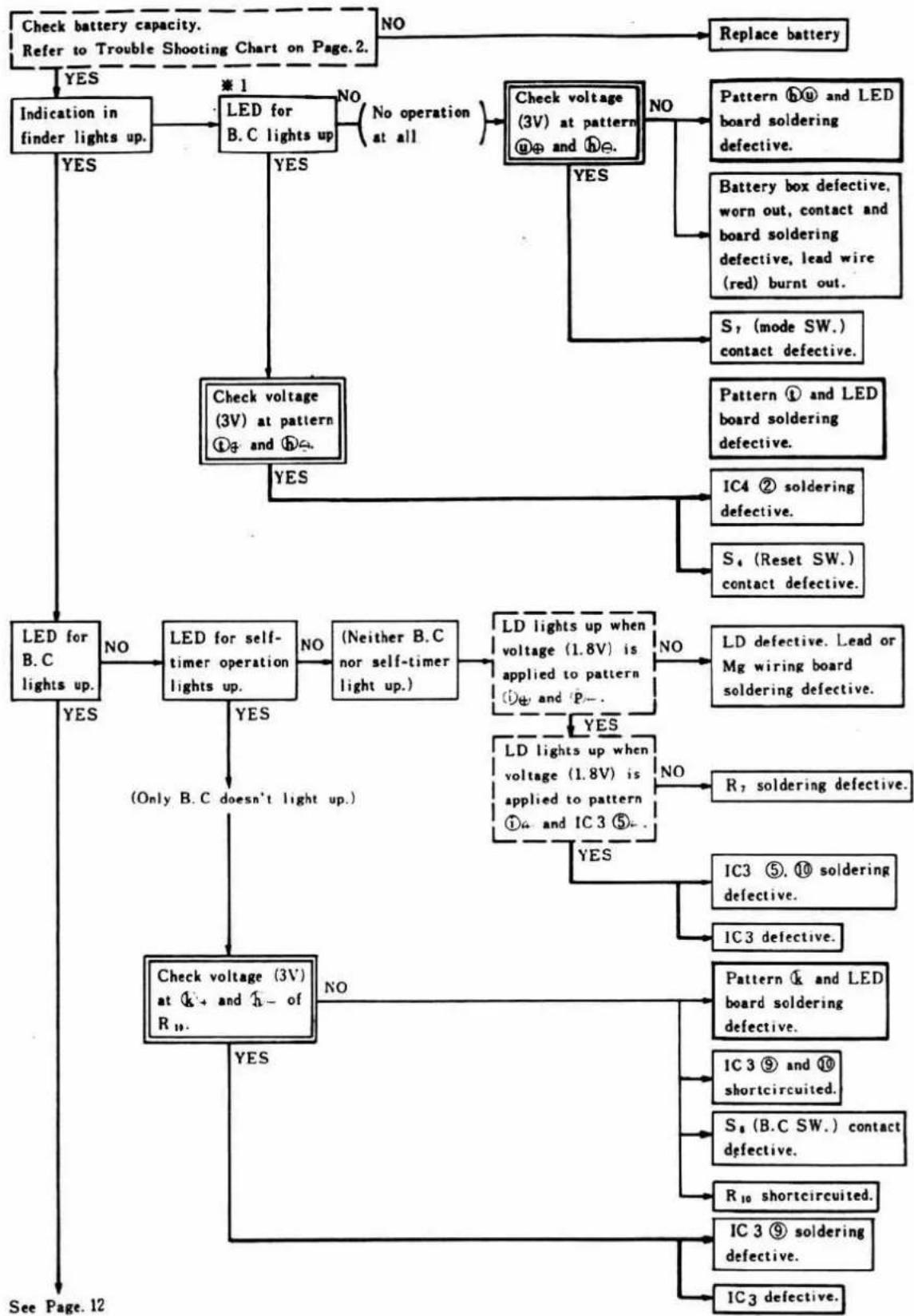
flowchart
graph TD
    A["Check battery capacity.<br>Refer to Trouble Shooting Chart on Page.2."] --> B{NO}
    B --> C["Replace battery"]
    A --> D{YES}
    D --> E["Indication in finder lights up."]
    E --> F{LED for B.C lights up.}
    F -->|NO| G{No operation at all}
    F -->|YES| H["Check voltage (3V) at pattern ①₃ and ②₄."]
    G --> I{Check voltage (3V) at pattern ④⊕ and ⑤⊖.}
    I -->|NO| J["Pattern ⑥⊕ and LED board soldering defective."]
    I -->|YES| K["S₁ (mode SW.) contact defective."]
    I -->|YES| L["Pattern ① and LED board soldering defective."]
    L --> M["IC4 ② soldering defective."]
    L --> N["S₄ (Reset SW.) contact defective."]
    O["LED for B.C lights up."] --> P{LED for self-timer operation lights up.}
    P -->|NO| Q{(Neither B.C nor self-timer light up.)}
    Q --> R{LD lights up when voltage (1.8V) is applied to pattern ①⊕ and ②⊕...}
    R -->|NO| S["LD defective. Lead or Mg wiring board soldering defective."]
    R -->|YES| T["LD lights up when voltage (1.8V) is applied to pattern ①₄ and IC3 ⑤..."]
    T --> U{R₇ soldering defective.}
    U --> V["IC3 ⑤. ⑩ soldering defective."]
    U -->|NO| W["IC3 defective."]
    T -->|YES| X["Check voltage (3V) at ④+ and ⑤- of R₁₀."]
    X --> Y{Check voltage (3V) at ④+ and ⑤- of R₁₀.}
    Y -->|NO| Z["Pattern ④ and LED board soldering defective."]
    Y -->|YES| AA["IC3 ⑨ and ⑩ shortcircuited."]
    AA --> AB["S₈ (B.C SW.) contact defective."]
    AA --> AC["R₁₀ shortcircuited."]
    AA --> AD["IC 3 ⑨ soldering defective."]
    AA --> AE["IC3 defective."]
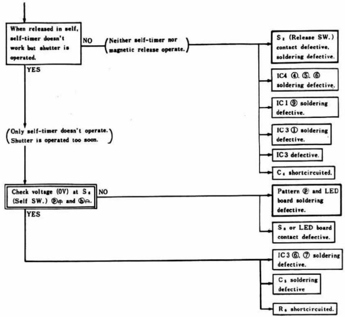
flowchart
graph TD
    A["When released in self, self-timer doesn't work but shutter is operated."] -->|YES| B["(Only self-timer doesn't operate. Shutter is operated too soon.)"]
    A -->|NO| C["S₂ (Release SW.) contact defective, soldering defective."]
    C --> D["IC4 ④. ⑤. ⑥ soldering defective."]
    D --> E["IC1 ⑨ soldering defective."]
    E --> F["IC3 ① soldering defective."]
    F --> G["IC3 defective."]
    G --> H["C₄ shortcircuited."]
    H --> I["Pattern ⑨ and LED board soldering defective."]
    I --> J["S₄ or LED board contact defective."]
    J --> K["IC3 ⑥. ⑦ soldering defective."]
    K --> L["C₄ soldering defective"]
    L --> M["R₄ shortcircuited."]
    M --> I
    A -->|YES| N["Check voltage (0V) at S₄ (Self SW.) ⑨φ and ⑩Ω."]
    N --> O["NO"]
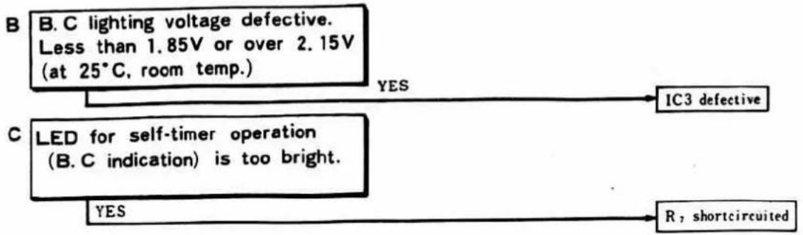
flowchart
graph TD
    A["B. C lighting voltage defective.<br>Less than 1.85V or over 2.15V<br>(at 25°C, room temp.)"] -->|YES| B["IC3 defective"]
    C["C LED for self-timer operation<br>(B. C indication) is too bright."] -->|YES| D["R, shortcircuited"]
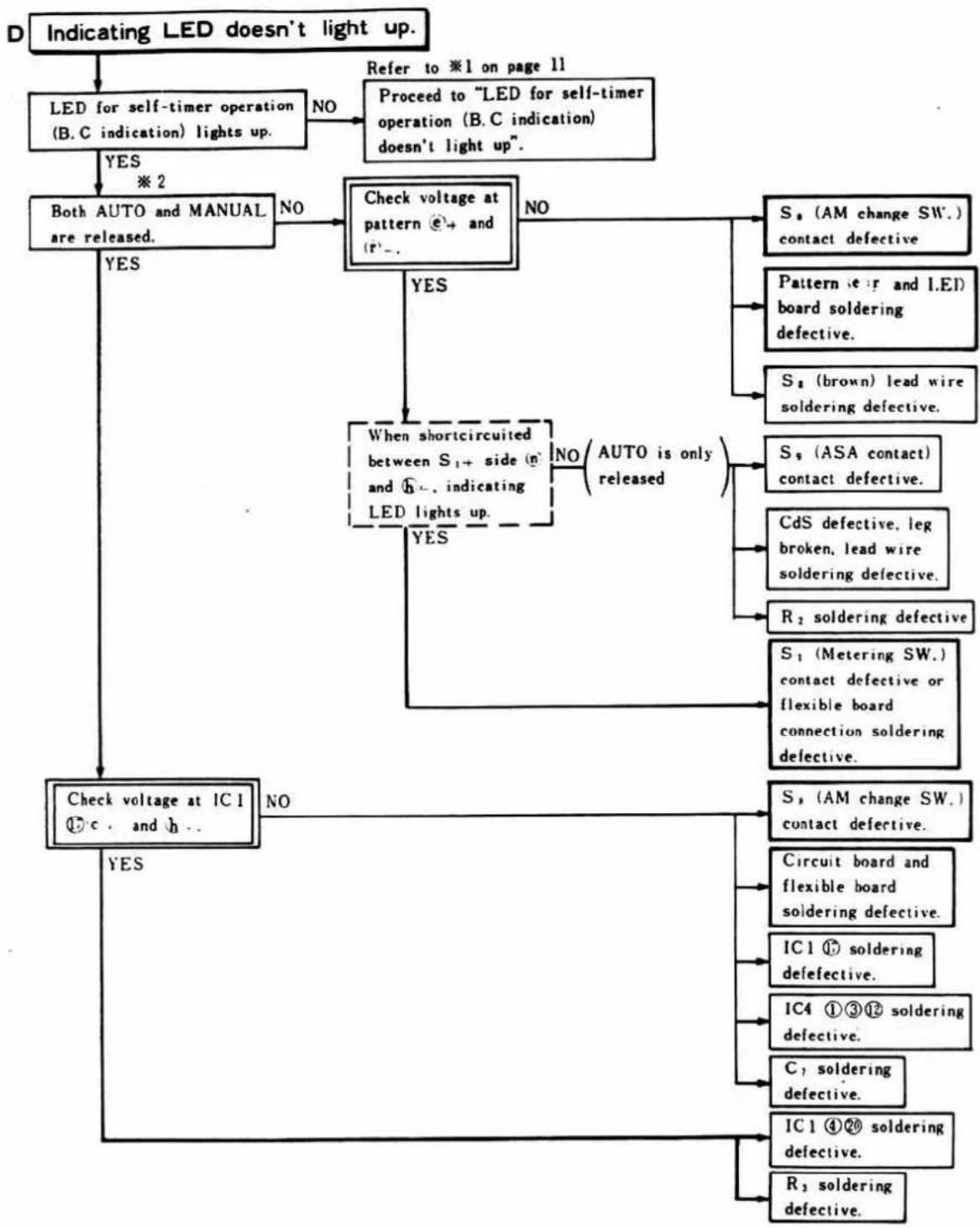
flowchart
graph TD
    A["Indicating LED doesn't light up."] --> B["LED for self-timer operation (B.C indication) lights up."]
    B -->|YES ※2| C["Both AUTO and MANUAL are released."]
    B -->|NO Refer to *1 on page 11
Proceed to "LED for self-timer operation (B.C indication) doesn't light up".]
    C -->|YES| D["Check voltage at pattern Ⓞ+ and (r-)."]
    C -->|NO| E["When shortcircuited between S₁+ side (n) and Φ-, indicating LED lights up."]
    E -->|YES| F["Check voltage at IC1 ①c, and h..."]
    E -->|NO| G["AUTO is only released"]
    G --> H["S₁ (AM change SW.) contact defective"]
    G --> I["Pattern (r and LED) board soldering defective"]
    G --> J["S₂ (brown) lead wire soldering defective"]
    G --> K["S₃ (ASA contact) contact defective"]
    G --> L["CdS defective, leg broken, lead wire soldering defective"]
    G --> M["R₂ soldering defective"]
    G --> N["S₁ (Metering SW.) contact defective or flexible board connection soldering defective"]
    G --> O["S₂ (AM change SW.) contact defective"]
    O --> P["Circuit board and flexible board soldering defective"]
    O --> Q["IC1 ⑰ soldering defective"]
    O --> R["IC4 ①③⑫ soldering defective"]
    O --> S["C₁ soldering defective"]
    O --> T["IC1 ④⑳ soldering defective"]
    O --> U["R₂ soldering defective"]
    D --> V["YES"]
    V --> W["Check voltage at IC1 ①c, and h..."]
    W --> X["NO"]
E
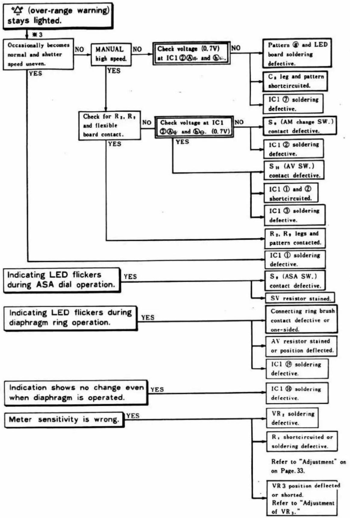
flowchart
graph TD
    A["(over-range warning) stays lighted."] --> B["Occasionally becomes normal and shutter speed uneven."]
    B -->|NO| C["MANUAL high speed."]
    C -->|YES| D["Check for R₂, R₁ and flexible board contact."]
    C -->|NO| E["Check voltage (0.7V) at IC1 ②Aφ and Φε."]
    E -->|YES| F["Indicating LED flickers during ASA dial operation."]
    E -->|NO| G["Check voltage at IC1 ②Aφ and Φε. (0.7V)"]
    G -->|YES| H["Indicating LED flickers during diaphragm ring operation."]
    G -->|NO| I["SV resistor stained."]
    I --> J["Connecting ring brush contact defective or one-sided."]
    J --> K["Indication shows no change even when diaphragm is operated."]
    G -->|NO| L["IC1 ① soldering defective."]
    L --> M["IC1 ③ soldering defective."]
    M --> N["Sₙ (AM change SW.) contact defective."]
    N --> O["Cₙ leg and pattern shortcircuited."]
    O --> P["IC1 ⑦ soldering defective."]
    G -->|YES| Q["IC1 ① and ② shortcircuited."]
    Q --> R["S₁₁ (AV SW.) contact defective."]
    R --> S["S₂, R₃ legs and pattern contacted."]
    S --> T["IC1 ① soldering defective."]
    T --> U["Sₙ (ASA SW.) contact defective."]
    U --> V["Sₙ resistor stained."]
    V --> W["IC1 ⑱ soldering defective."]
    W --> X["IC1 ⑲ soldering defective."]
    X --> Y["VR₂ soldering defective."]
    Y --> Z["R₁ shortcircuited or soldering defective."]
    Z --> AA["Refer to "Adjustment" on Page.33."]
    Y --> AB["VR3 position deflected or shorted. Refer to "Adjustment of VR₃.""]
    B --> AC[" occasionally becomes normal and shutter speed uneven."]
    AC -->|NO| AD["Manual high speed."]
    AD -->|YES| AE["Check for R₂, R₁ and flexible board contact."]
    AE -->|YES| AF["Indicating LED flickers during ASA dial operation."]
    AF --> AG["Indication shows no change even when diaphragm is operated."]
    AG --> AH["Meter sensitivity is wrong."]
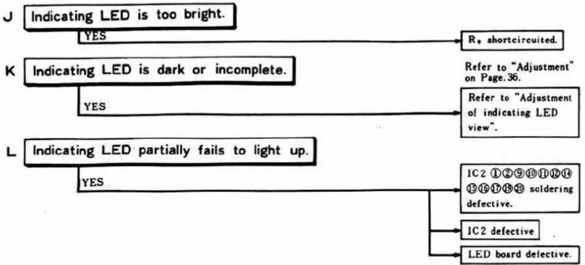
flowchart
graph TD
    J["Indicating LED is too bright."] -->|YES| R["R, shortcircuited."]
    K["Indicating LED is dark or incomplete."] -->|YES| Refer["Refer to "Adjustment" on Page.36."]
    L["Indicating LED partially fails to light up."] -->|YES| IC2_1["IC2 ①②⑨⑩⑪⑫⑭⑭⑮ soldering defective."]
    L --> IC2_Defective["IC2 defective"]
    L --> LED_BoardDefective["LED board defective."]
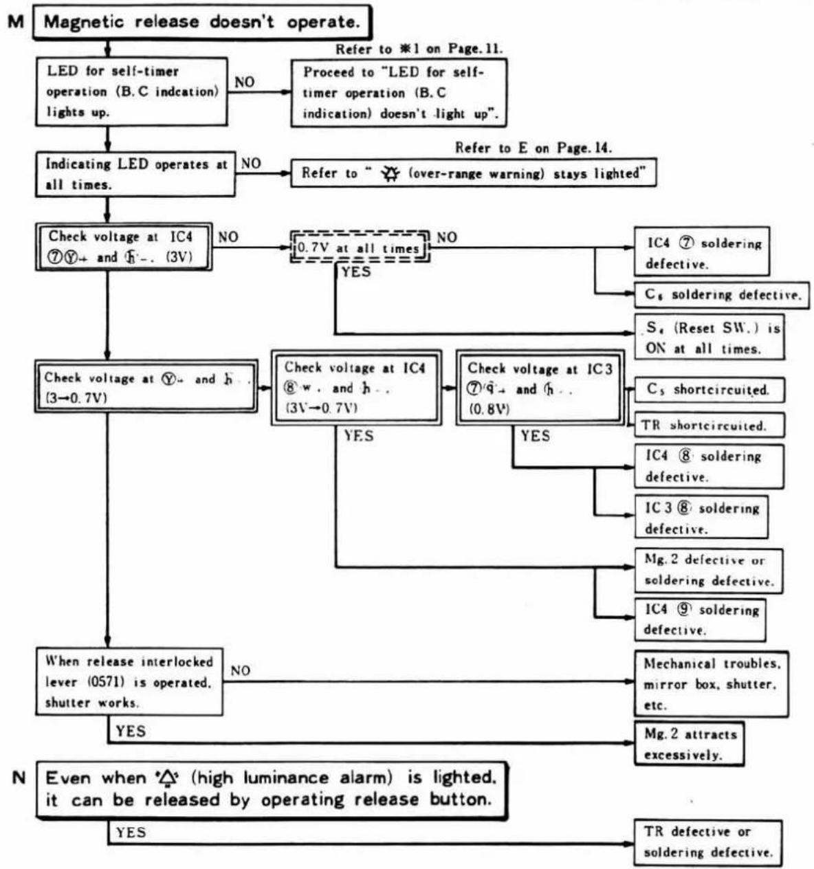
flowchart
graph TD
    A["Magnetic release doesn't operate."] --> B["LED for self-timer operation (B.C indication) lights up."]
    B -->|NO| C["Proceed to "LED for self-timer operation (B.C indication) doesn't light up"."]
    B --> D["Indicating LED operates at all times."]
    D -->|NO| E["Refer to " (over-range warning) stays lighted""]
    D --> F["Check voltage at IC4 ⑦Y+ and h-. (3V)"]
    F -->|NO| G["0.7V at all times"]
    F -->|YES| H["IC4 ⑦ soldering defective."]
    F --> I["Check voltage at IC4 ⑧w. and h-. (3V→0.7V)"]
    G --> J["C5 soldering defective."]
    G --> K["S4 (Reset SW.) is ON at all times."]
    G --> L["C5 shortcircuited."]
    G --> M["TR shortcircuited."]
    G --> N["IC4 ⑧ soldering defective."]
    G --> O["IC3 ⑧ soldering defective."]
    G --> P["Mg.2 defective or soldering defective."]
    G --> Q["IC4 ⑨ soldering defective."]
    F --> R["Check voltage at IC3 ⑦q+ and h-. (0.8V)"]
    R --> S["YES"]
    R --> T["Check voltage at IC4 ⑧ w. and h-. (3V→0.7V)"]
    T --> U["Mg.2 defects excessively."]
    R --> V["When release interlocked lever (0571) is operated, shutter works."]
    V --> W["NO"]
    V --> X["Tr defective or soldering defective."]
    Y["N Even when △ (high luminance alarm) is lighted, it can be released by operating release button."] --> Z["YES"]
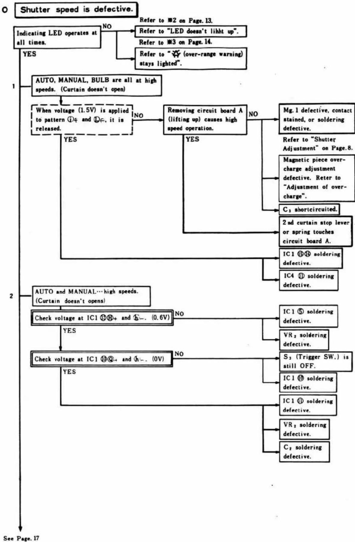
flowchart
graph TD
    A["Shutter speed is defective."] --> B["Indicating LED operates at all times."]
    B -->|NO| C["Refer to *2 on Page.13."]
    B -->|Yes| D["AUTO, MANUAL, BULB are all at high speeds. (Curtain doesn't open)"]
    C --> E["Refer to *3 on Page.14."]
    C --> F["Removing circuit board A (lifting up) causes high speed operation."]
    D --> G["When voltage (1.5V) is applied to pattern ①4 and ②e, it is released."]
    F --> H["No"]
    H --> I["Mg.1 defective, contact stained, or soldering defective."]
    F --> J["Yes"]
    J --> K["Magnetic piece over-charge adjustment defective. Refer to "Adjustment of over-charge"."]
    K --> L["C3 shortcircuited."]
    J --> M["2nd curtain stop lever or spring touches circuit board A."]
    M --> N["IC1 ⑮⑯ soldering defective."]
    M --> O["IC4 ⑪ soldering defective."]
    P["AUTO and MANUAL…high speeds. (Curtain doesn't opens)"] --> Q["Check voltage at IC1 ⑰④ and ⑤… (0.6V)."]
    Q --> R["NO"]
    R --> S["IC1 ⑤ soldering defective."]
    Q --> T["VR2 soldering defective."]
    P --> U["Check voltage at IC1 ⑩④ and ⑪… (0V)."]
    U --> V["NO"]
    V --> W["S3 (Trigger SW.) is still OFF."]
    U --> X["IC1 ⑩ soldering defective."]
    U --> Y["IC1 ⑪ soldering defective."]
    U --> Z["VR2 soldering defective."]
    U --> AA["C2 soldering defective."]
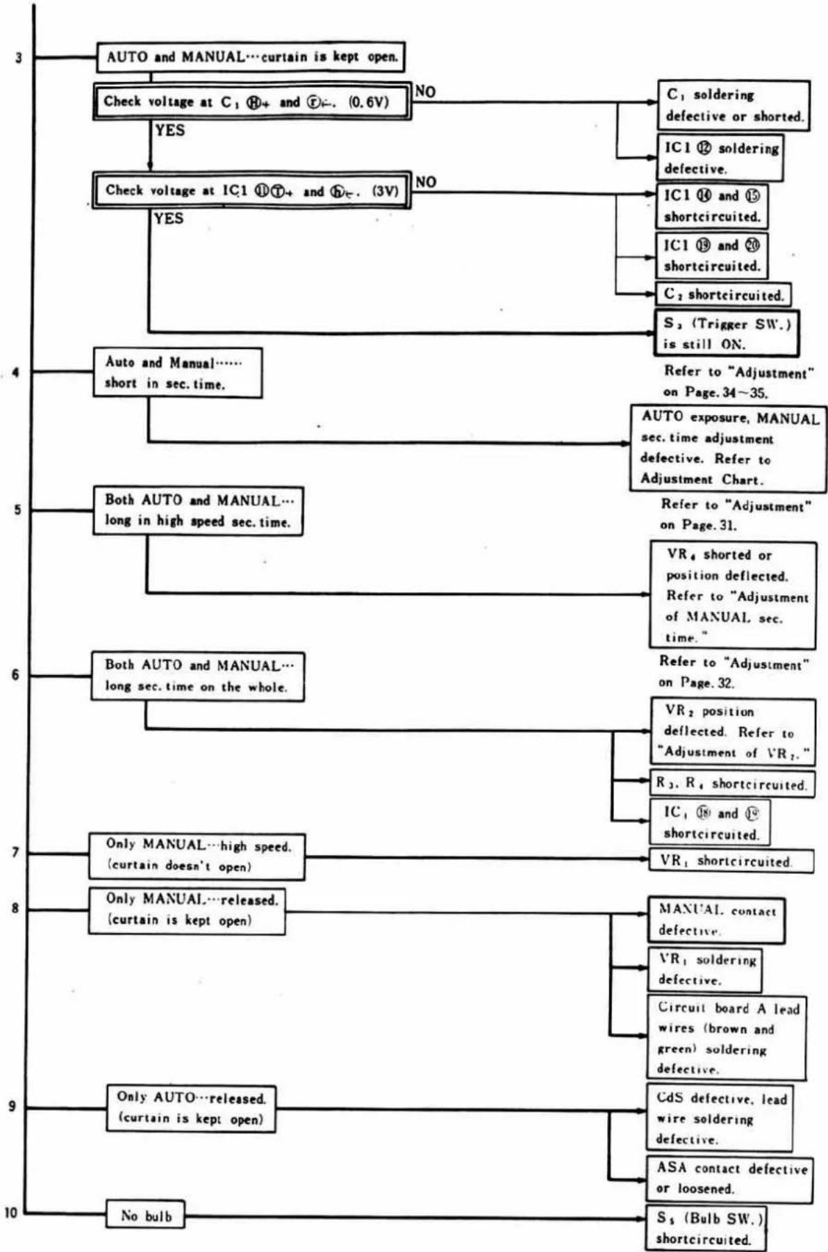
flowchart
graph TD
    A["3 AUTO and MANUAL…curtain is kept open."] --> B["Check voltage at C₁⑧+ and ⑦- (0.6V)"]
    B -->|YES| C["Check voltage at IC1⑪⑦+ and ⑤- (3V)"]
    B -->|NO| D["C₁ soldering defective or shorted."]
    D --> E["IC1⑫ soldering defective."]
    E --> F["IC1⑭ and ⑮ shortcircuited."]
    F --> G["IC1⑮ and ⑰ shortcircuited."]
    G --> H["C₂ shortcircuited."]
    H --> I["S₂ (Trigger SW.) is still ON."]
    C --> J["4 Auto and Manual……short in sec. time."]
    J --> K["Refer to "Adjustment" on Page. 34~35."]
    K --> L["AUTO exposure, MANUAL sec. time adjustment defective. Refer to Adjustment Chart."]
    L --> M["5 Both AUTO and MANUAL…long in high speed sec. time."]
    M --> N["Refer to "Adjustment" on Page. 31."]
    N --> O["6 Both AUTO and MANUAL…long sec. time on the whole."]
    O --> P["VR₄ shorted or position deflected. Refer to "Adjustment of MANUAL sec. time.""]
    P --> Q["Refer to "Adjustment" on Page. 32."]
    Q --> R["7 Only MANUAL…high speed. (curtain doesn't open)"]
    R --> S["VR₁ shortcircuited."]
    S --> T["8 Only MANUAL…released. (curtain is kept open)"]
    T --> U["MANUAL contact defective."]
    U --> V["VR₁ soldering defective."]
    V --> W["Circuit board A lead wires (brown and green) soldering defective."]
    W --> X["9 Only AUTO…released. (curtain is kept open)"]
    X --> Y["CdS defective, lead wire soldering defective."]
    Y --> Z["ASA contact defective or loosened."]
    Z --> AA["S₃ (Bulb SW.) shortcircuited."]
    AA --> AB["10 No bulb"]
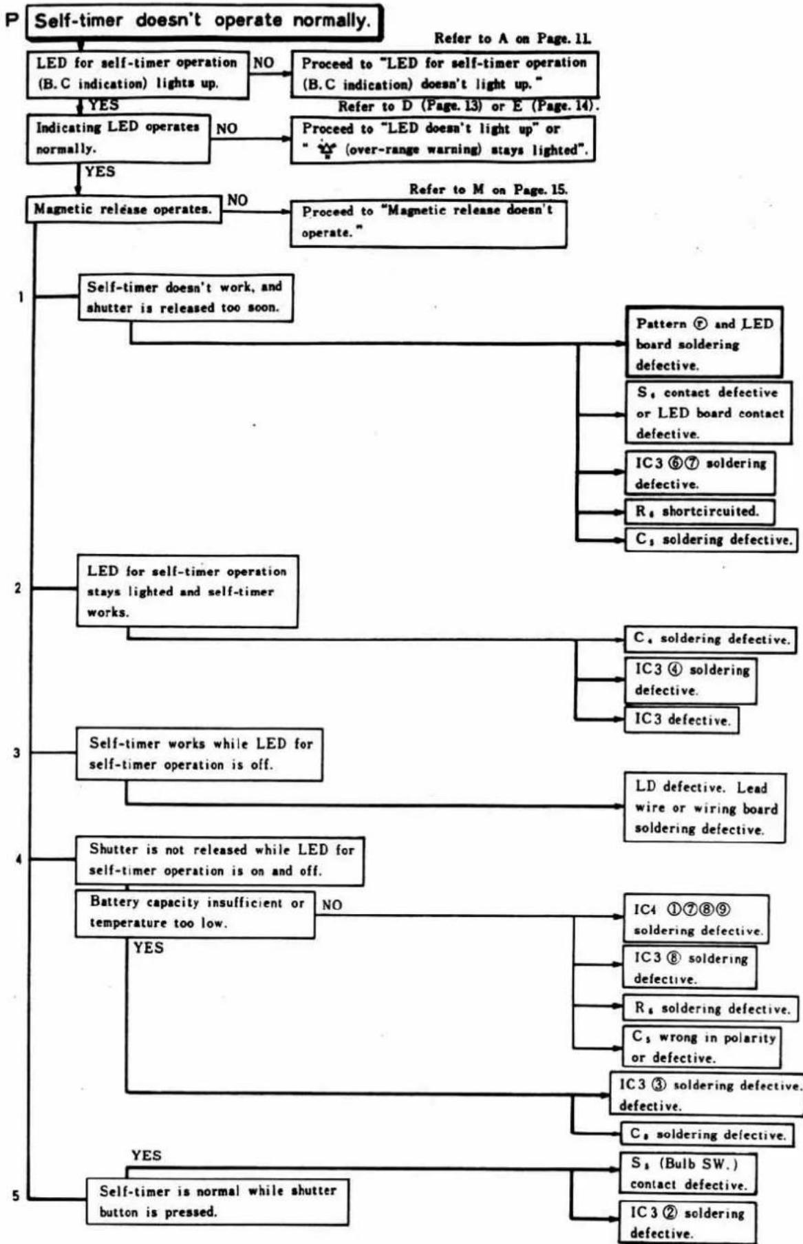
flowchart
graph TD
    A["Self-timer doesn't operate normally."] --> B["LED for self-timer operation (B.C indication) lights up."]
    B -->|YES| C["Indicating LED operates normally."]
    B -->|NO| D["Proceed to "LED for self-timer operation (B.C indication) doesn't light up.""]
    D --> E["Proceed to "LED doesn't light up" or "(over-range warning) stays lighted"."]
    C -->|YES| F["Magnetic release operates."]
    C -->|NO| G["Proceed to "Magnetic release doesn't operate.""]
    F --> H["Self-timer doesn't work, and shutter is released too soon."]
    H --> I["Pattern ⑦ and LED board soldering defective."]
    H --> J["S₁ contact defective or LED board contact defective."]
    H --> K["IC3 ⑥⑦ soldering defective."]
    H --> L["R₁ shortcircuited."]
    H --> M["C₁ soldering defective."]
    I --> N["LED for self-timer operation stays lighted and self-timer works."]
    J --> N
    K --> N
    L --> N
    M --> N
    N --> O["Self-timer works while LED for self-timer operation is off."]
    O --> P["LD defective. Lead wire or wiring board soldering defective."]
    N --> Q["Shutter is not released while LED for self-timer operation is on and off."]
    Q --> R["Battery capacity insufficient or temperature too low."]
    R --> S["IC4 ①⑦⑧⑨ soldering defective."]
    R --> T["IC3 ⑧ soldering defective."]
    R --> U["R₁ soldering defective."]
    R --> V["C₁ wrong in polarity or defective."]
    R --> W["IC3 ③ soldering defective. defective."]
    S --> X["IC4 ①⑦⑧⑨ soldering defective."]
    T --> Y["IC3 ⑧ soldering defective."]
    U --> Z["S₁ (Bulb SW.) contact defective."]
    V --> AA["IC3 ② soldering defective."]
    W --> AB["C₁ soldering defective."]
    X --> AC["Self-timer is normal while shutter button is pressed."]
    Y --> AD["S₁ (Bulb SW.) contact defective."]
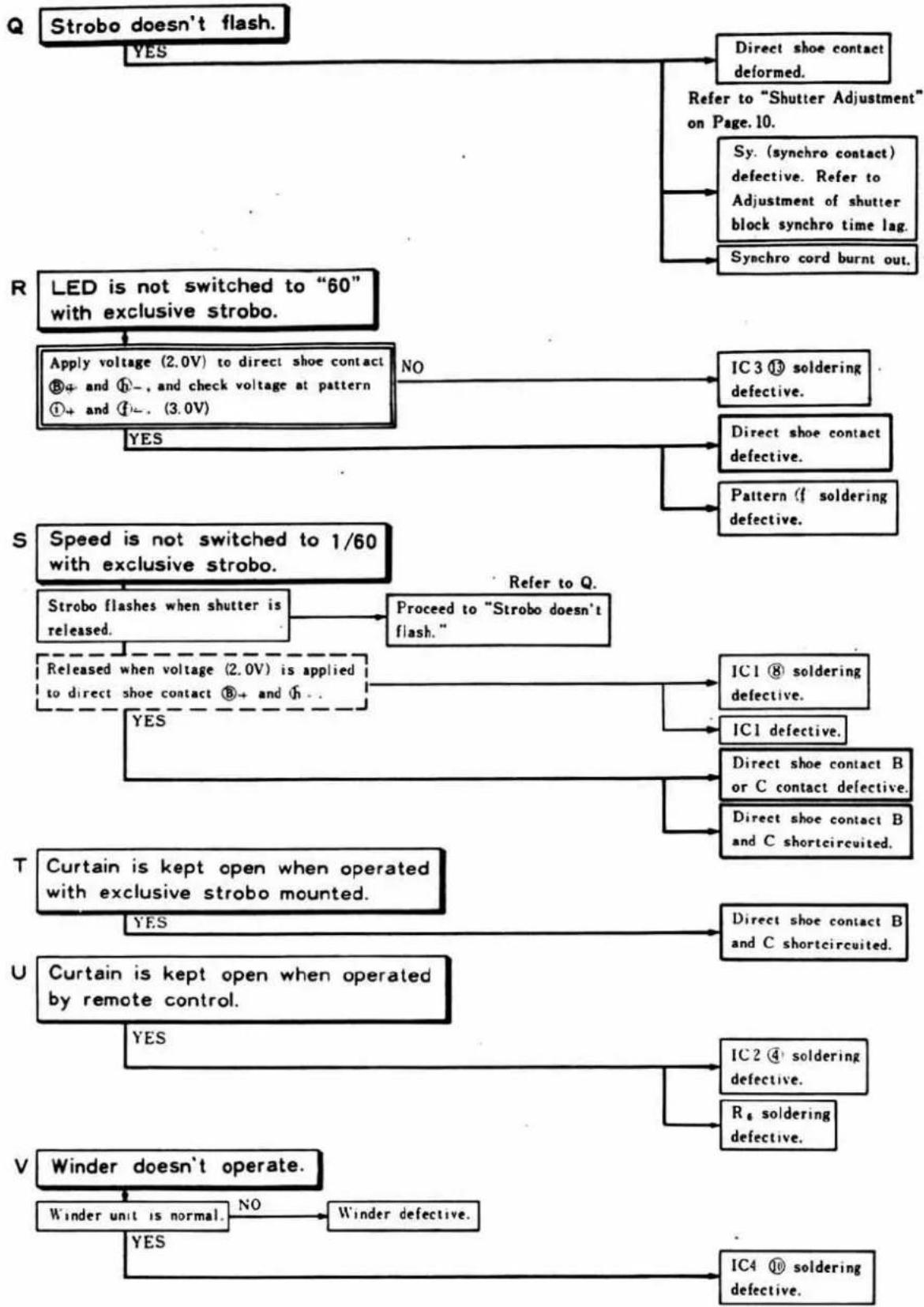
flowchart
graph TD
    A["Strobo doesn't flash."] -->|YES| B["Direct shoe contact deformed."]
    A -->|Refer to "Shutter Adjustment" on Page 10.]
    A -->|Sy. (synchro contact) defective. Refer to Adjustment of shutter block synchro time lag.]
    A -->|Synchro cord burnt out.]

    C["LED is not switched to "60" with exclusive strobo."] --> D["Apply voltage (2.0V) to direct shoe contact ®+ and ①-, and check voltage at pattern ①+ and ④-.. (3.0V)"]
    D -->|NO| E["IC3 ⑬ soldering defective."]
    D -->|YES| F["Pattern ⑦ soldering defective."]

    G["Speed is not switched to 1/60 with exclusive strobo."] --> H["Strobo flashes when shutter is released."]
    H --> I["Proceed to "Strobo doesn't flash.""]
    I --> J["IC1 ⑧ soldering defective."]
    I --> K["IC1 defective."]
    I --> L["Released when voltage (2.0V) is applied to direct shoe contact ®+ and ⑦..."]
    L --> M["Direct shoe contact B or C contact defective."]
    L --> N["IC1 defective."]
    L --> O["Direct shoe contact B and C shortcircuited."]

    P["Curtain is kept open when operated with exclusive strobo mounted."] --> Q["Direct shoe contact B and C shortcircuited."]
    P --> R["IC1 defective."]
    P --> S["T: Curtain is kept open when operated by remote control."]
    S --> T["IC2 ⑭ soldering defective."]
    S --> U["U: Curtain is kept open when operated by remote control."]
    U --> V["IC4 ⑮ soldering defective."]
    U --> W["V: Winder unit is normal. NO Winder defective."]
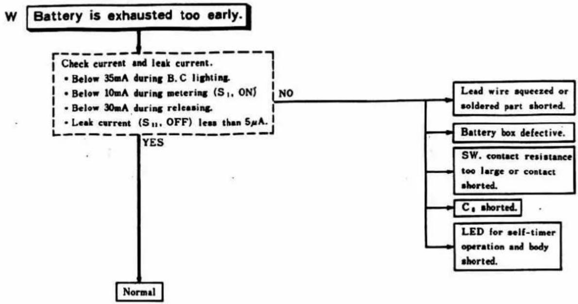
flowchart
graph TD
    A["Battery is exhausted too early."] --> B{Check current and leak current.}
    B -->|YES| C["Normal"]
    B -->|NO| D["Lead wire squeezed or soldered part shorted."]
    B --> E["Battery box defective."]
    B --> F["SW. contact resistance too large or contact shorted."]
    B --> G["C₁ shorted."]
    B --> H["LED for self-timer operation and body shorted."]
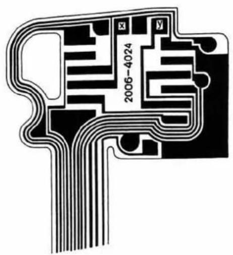
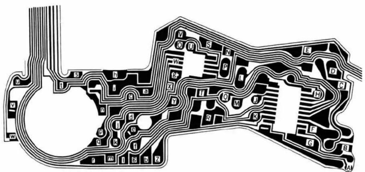
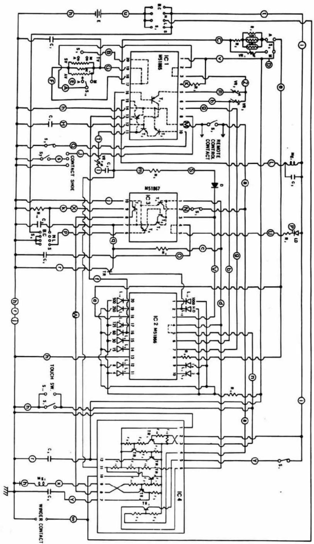
Inspection Specification
- This specification includes the allowable quality levels in the production line so that we can guarantee the quality of products to the general users. The specifications are given in detail item by item so that you can refer to them when handling the requirements of users. Also, you can use the specifications for rechecking the products after completion of repair.
- When carrying out outgoing or incoming inspections, do not directly apply the specifications to the measured values but correctly understand the purposes of the inspections and then do the checkings, for instance, in accordance with the incoming inspection specification manual.
- Some users with special purposes may sometimes require different specifications because they are not satisfied with this specification. In that case, give priority to the users' requests and then make the necessary adjustments after checking to see if they are possible or not.
| Item | Check point | Contents | Checking Adjustment(Refer to Disass')-Ass'y. Adjust manual) | |||
| Winding | Winding lever | Not smooth (uneven, catching), shifted back, noise, vertically loose.Winding torque...less than 4 kg·cm (with film). | P.23, 24 | |||
| Spool | Operation...Not smooth (uneven, squeaky). Check film winding.No-load operation...250±50 g. | P.3, 4 | ||||
| Sprocket | Operation...Slip, back lash (after winding). Operation with rewind button depressed (uneven, catching). Claw position. | P.2, 4 | ||||
| Rewinding | Rewind button | Operation...Depressing, releasing, catching, uneven.Rewind button lock position...over 0.3 mm(from bottom of lower cover). | P.3 | |||
| Rewind crank | Operation...Off-center, squeaky, gritty, defective spring.Film rewinding resistance...250~650 g. | P.46 | ||||
| Film counter | Feed | Operation...When wound twice from S, indication should be 1.It should correctly operate up to 36+1. Check for failure, standstill, skip, deflection.Deflection of scale position...Center of letter should be within  the ra should the ra should  | P.6, 10 | |||
| Return | Operation...It should return to S when back cover is opened. | |||||
| Film signal | Appearance | Operation...Signal should be as illustrated at the 1st frame on counter, midway, 36+2 frames.Check for unsmooth operation (catching, etc).No film 1st frame Midway 36+2 frames    over 1/4 Slightly visible over 1/4 Slightly visible | P.7 | |||
| Disappearance | Operation...Signal should disappear just before film is disengaged from spool in rewinding. | |||||
| Item | Check point | Contents | Checking-Adjustment(Refer to Dissay)-Ass'y-Adjust manual) | |||
| Shutter | Shutter button | Operation···Not smooth, loose, catching, shock, stained, wrong position.Operating-resistance···250±50g.After-operation allowance···over 0.2mm | P.24, 46 | |||
| Speed dial | Operation···Not smooth, clicking, auto lock, loose.Auto lock···Loose, squeaky, gritty, etc.Scale deflection···Center of letter should be aligned to index.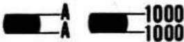 | P.46 | ||||
| Shutter curtain | Operation···Overlap, return (during little-by-little winding), bounce, 2nd curtain appearance (in slow shutter), bump, stop, noise.Curtain speed···Within 13 ms for both 1st and 2nd curtains. | P.47~51 | ||||
| Shutter speed | Allowable range···Refer to P.5. | P.34 | ||||
| Synchro | Conduction···Light emission. No shorting during winding.Delay timeContact Shutter speed Measurement AllowablerangeX 1/60 & strobo auto Time until contact is ON aftercurtain running. (A range) over0.3msTime until curtain appearanceafter contact is ON. (B range) over2msContact efficiencyContact Measuring time Shutter speed AllowablerangeX 1.0ms 1/60 & strobo auto over 60%Insulation resistance···over 10MΩ (250V D.C resistance meter) | P.40 | ||||
| Operating switch | Lever | Operation···Clicking, deflection, return, not smooth, catching, defective spring. Return to ON position after B.C check, return to click position from lever contact position self side.Letter indication should be aligned to lever index.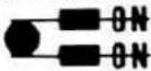 | P.45 | |||
| Self-timer | Operation···Lamp should start blinking within 1 sec. after S button release, and blinking cycle should become faster just before release.Alteration of blinking cycle: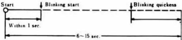 | P.39 | ||||
| Contact | Shutter speed | Measurement | Allowable range |
| X | 1/60 & strobo auto | Time until contact is ON after curtain running. (A range) | over 0.3 ms |
| Time until curtain appearance after contact is ON. (B range) | over 2 ms |
| Contact | Measuring time | Shutter speed | Allowable range |
| X | 1.0 ms | 1/60 & strobo auto | over 60% |
| Item | Check point | Contents | Checking Adjustment(Refer to Disass')-Ass'y. Adjust manual) | ||||
| Operating switch | Battery Checker | Operation...Lamp should be lighted exactly.Lamp should be on in the range from 1/2 or over to B.C contact. 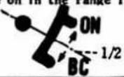 | P.38 | ||||
| Focus | Mirror | Operation...Loose, two-step, timing, wrong position, bounce.Stop position...45°±30°Raising position...It should be unseen behind flare preventing board. | P.16 | ||||
| Body back | 43.70±0.01 mm | P.43 | |||||
| Finder back | 43.56±0.025 mm | P.44 | |||||
| Finder | View | Image turnover,∞ matching, scale plate deflection. | P.44 | ||||
| Speed figure band | Scratches, dust, stains, etc.Figure and LED should be positioned within figure band. | P.19 | |||||
| Back cover | Opening, Clos-ing | Operation...Locking, looseness after locking. It should smoothly release when rewinding knob is shifted up. | P.10 | ||||
| Pressure plate | Distortion, projection, irregular surfaces, impurities, stains, inclining, easy to come loose. | ||||||
| Auto exposure | ASA dial | Operation...Not smooth, catching, deflecting.For ASA letter, scale and frame, the 3rd scale should be visible.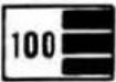 correct, or correct, or 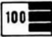 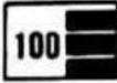 | P.25, 46 | ||||
| Over-rang noninter locked lock | LENS: 50mm F1.4 ASA: 100 | P.37 | |||||
| Luminance | F | Shutter speed | Allowable range | Spec. | |||
| EV 15 | F 5.6 | 1000 | Lock should be effective at EV 16.25. | +1.25 EV | |||
| Release should be possible at EV 14.25. | -0.75 EV | ||||||
| It should be exactly locked with 1000 or 1000 LED lamp lighted. | |||||||
| Luminance | F | Shutter speed | Allowable range | Spec. |
| EV 15 | F 5.6 | 1000 | Lock should be effective at EV 16.25. | +1.25 EV |
| Release should be possible at EV 14.25. | -0.75 EV |
| Item | Check point | Contents | Checking Adjustment(Refer to Disass'y-Ass'y-Adjust manual) | ||
| Auto exposure | LED indication | Scratches, dust, cloud, light leakage (with dark finder)LED difference...LENS: 50 mm F1.4 ASA: 100, Auto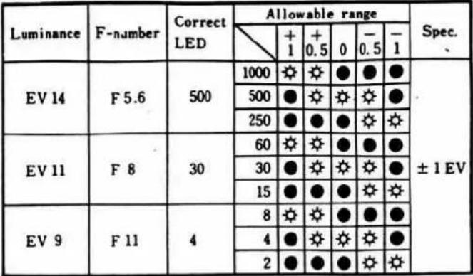 LED other than correct LED and adjacent LED should not be lighted.LED lighting voltage...2.0 V (in darkness). LED other than correct LED and adjacent LED should not be lighted.LED lighting voltage...2.0 V (in darkness). | P.19, 33, 35 | ||
| Exposure correction | Operation...Not smooth, clicking, lock release. | P.26 | |||
| Exposure error | LENS: 50 mm F1.4 ASA: 100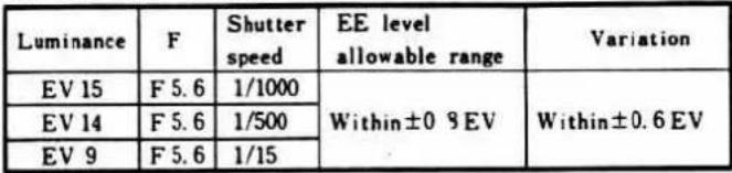 | P.35 | |||
| Other performance | Checker voltage | Room temperature: 25°C | P.38 | ||
| Voltage | Allowable | Spec. | |||
| 2.0 V | • Should be on at 2.15 V | +0.15V | |||
| • Should be off at 1.85 V | |||||
| Touch switch operating resistance | 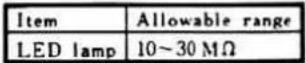 | P.36 | |||
| Release lock minimum voltage |  | P.37 | |||
| Performance assuring voltage | 2.15 V~3.0 V (constant voltage: 2.25~2.8 V) | P.40 | |||
| Current consumption | Constant voltage: 2.8V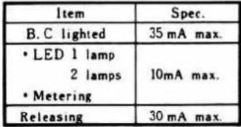 | — | |||
| Item | Check point | Contents | Checking-Adjustment (Refer to Dissay-)Ass'y-Adjust manual) | ||
| Other performance | Leak current | Constant voltage: 2.8V, 5μA max. | — | ||
| Accessories | Accessory | Looseness, spring pressure, removal, inclining.Safety switch strokeAccessory shoeShould be off when less than 1.7mm. | P.46 | ||
| Remote control terminal | Operation...It should be easy to detach.Looseness, heavy, release, catching.Cable release switch operation...70~300g. | P.13 | |||
| Synchro terminal | It should be easy to attach and detach.Looseness, stains, easy to come loose. | P.13 | |||
| Eye-piece attachment | Clicking, easy to come loose, inclined. | P.46 | |||
| Lens lock | Operation...Heavy, light, gritty, squeaky, loose. | P.14 | |||
| Others | Interchanges ability with exclusive strobo | LED 60 blinking with exclusive strobo charge completed. | P.42 | ||
| Item | Spec. | ||||
| LED blinking | (ON) voltage 2.0 V● (OFF) voltage 1.6V | ||||
| Tuning...With charge completed, it should be tuned irrespective of shutter dial position.Caution: The 300 Ω of resistor must connect to the plus side of power sause when measure it. | |||||
| Interchangeability with winder | Winder connecting terminal voltageWinding completed (S4 ON)...over 1.0VReleasing completed (S4 OFF)...below 0.2V | P.23 | |||
Shutter speed specification
| Specification\Speed | Strobo auto change 1/50 | 1 | 1/2 | 1/4 | 1/8 | 1/15 | 1/30 | 1/60 | 1/125 | 1/250 | 1/500 | 1/1000 |
| Standard value | 20 ms | 1000ms | 500ms | 250ms | 125ms | 62.5ms | 31.3ms | 15.6ms | 7.81ms | 3.91ms | 1.95ms | 0.977ms |
| Max. limit value | 23 ms | 1410ms | 707ms | 354ms | 177ms | 88.4ms | 44.3ms | 22.1ms | 11.0ms | 5.53ms | 2.76ms | 1.38ms |
| Min. limit value | 17 ms | 707ms | 354ms | 177ms | 88.4ms | 44.3ms | 22.1ms | 11.0ms | 5.53ms | 2.76ms | 1.38ms | 0.691ms |
| Specified value | +0.21 EV-0.23 EV | ±0.5 EV | ||||||||||
Shutter speed and uneven exposure
Exposure time at both ends (A, C ranges) to center (B range) should be within ±0.25%, and maximum and minimum values of B range should be within 0.4EV (+32% or -25%).
Shutter Parts List for XG series
- In this parts list, the type of shutters made available up to now since the beginning of the massproduction of 2006 series is classified into types 1\~4.
- See the parts list on the next page for each type.
- The part number on the exploded view of the parts list is sometimes provided with ● or ●.
● : Not interchangeable depending on the type of shutter.
● : Discontinued in the course of production, addition or temporarily used.
Regarding the parts provided with or , the description, differential points and replaceable type (common type) is given in the specified page of Parts List Part II.
- Inter changeability of shutter unit.
Shutter units (completed) of types 1\~4 are interchangeable, but pay attention for combinations of parts for body such as mirror return lever lock claw set (0522) and release operation lever spring (2035) shown below.
Type 4
Assy. Part No. 2006-0222-11
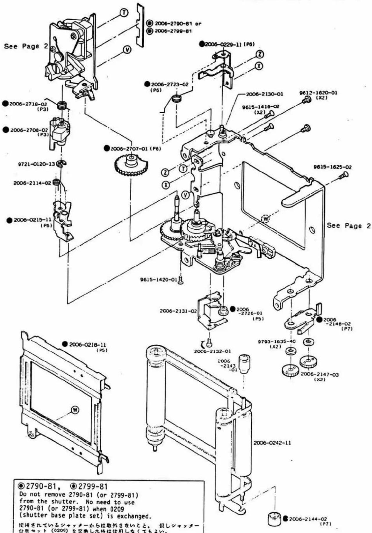
Shutter Parts List Part II
This parts list is for XG type shutter parts, in which modifications of parts with ● or Ⓞ mark are detailed.
- Indications Type 1\~4 are used for parts which differ with type of shutter unit, and there is no interchangeability between types.
- Parts indicated by Type A\~B are interchangeable with other types only when they come in a set with the relative parts of each type.
2nd. curtain release lever set 2 蔚解除レバーセノト
Control cam operation spring 制卵カム駆動SP
2nd. curtain release lever spring 2 蔚解除レバーSP
- 1st and 2nd curtain brake / 1, 2幕ブレーキ
To prevent breakage of 2nd curtain brake spring, tube (2221) is set to 2nd curtain brake spring (2192) for Type 3 shutter in the course of production. When disassembling Type 3 shutter with no the tube, set the tube by the method shown below.
(The tube is not needed for Type 3' and 4 shutters because the 2nd curtain brake lever set (0259) has been modified in shape.)
- Curtain shaft receiver-B / 幕軸受B
| Type 1. 2. 2'. 3. 3' | Type 4 |
2006-2126-01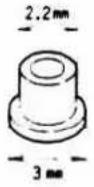 | 2006-2726-01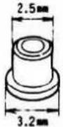 |
- 1st curtain stop lever / 1 暮係止レバー
| Type 1, 2, 2', 3, 3' | Type 4 |
2006-0212-12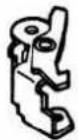 | 2006-0215-11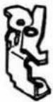 |
- 2nd curtain stop lever / 2幕係止レバー
| Type 1 | Type 2. 2'. 3. 3' | Type 4 |
2006-0219-11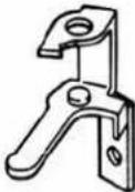 | 2006-0219-12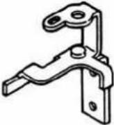 | 2006-0229-11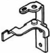 |
2006-2123-01 | 2006-2123-03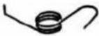 | 2006-2723-02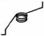 |
Disassembly, Assembly and Adjustment
For disassembly, refer to the related pages in the reverse order as the contents of this manual are arranged in the order of procedures for assembling and adjusting.
— Abbreviations —
: Assembly noto and reference.
☐ : Oil to be used and where to apply it.
B: Bond to be used and where to bind.
T: Special tool No. and where to use it.
■ Assembling/Adjustment Procedures Chart
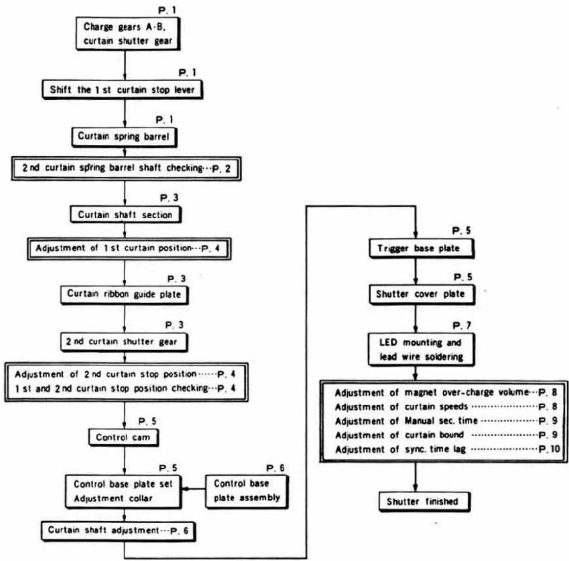
flowchart
graph TD
    A["Charge gears A·B, curtain shutter gear"] -->|P.1| B["Shift the 1st curtain stop lever"]
    B -->|P.1| C["Curtain spring barrel"]
    C --> D["2nd curtain spring barrel shaft checking...P.2"]
    D -->|P.3| E["Curtain shaft section"]
    E --> F["Adjustment of 1st curtain position...P.4"]
    F -->|P.3| G["Curtain ribbon guide plate"]
    G -->|P.3| H["2nd curtain shutter gear"]
    H --> I["Adjustment of 2nd curtain stop position....P.4\n1st and 2nd curtain stop position checking...P.4"]
    I -->|P.5| J["Control cam"]
    J --> K["Control base plate set\nAdjustment collar"]
    K --> L["Curtain shaft adjustment...P.6"]
    L --> M["Shutter finished"]
    N["Trigger base plate"] -->|P.5| O["Shutter cover plate"]
    O -->|P.7| P["LED mounting and lead wire soldering"]
    P --> Q["Adjustment of magnet over-charge volume...P.8\nAdjustment of curtain speeds....P.8\nAdjustment of Manual sec. time....P.9\nAdjustment of curtain bound....P.9\nAdjustment of sync. time lag....P.10"]
    Q --> R["Control base plate assembly"]
    R --> K
① Charge gears A·B, First curtain shutter gear, and curtain spring barrel
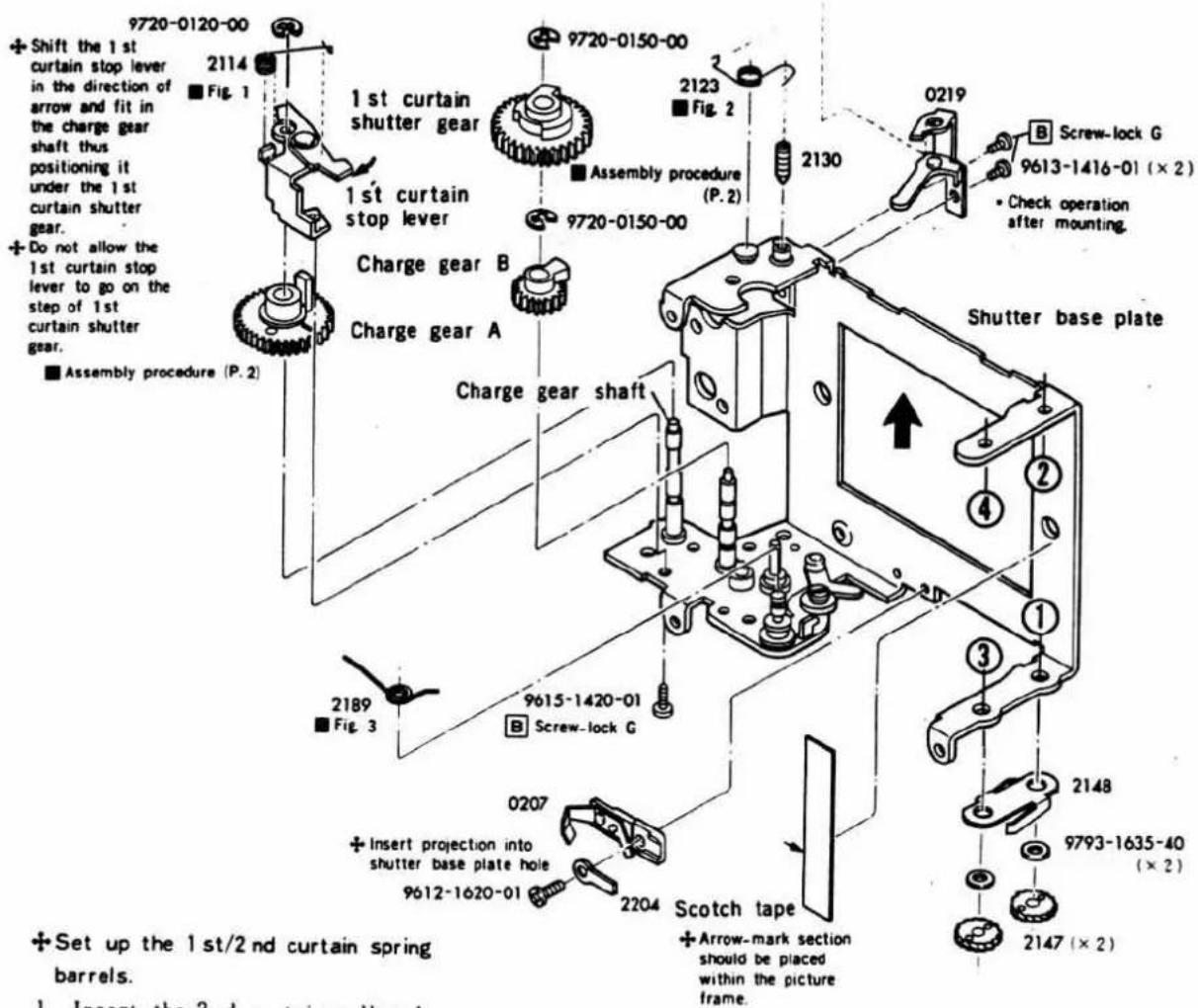
+Set up the 1st/2nd curtain spring barrels.
1. Insert the 2nd curtain roller A (2143) B (2144) into the 1st curtain spring barrel. And mount the 1st/2nd curtain spring barrel shaft onto the shutter base plate in the order of numbers.
- When mounting No. ④, slightly widen the shutter base plate in the direction of arrow.
2. Turn the curtain spring stop plate on the 2nd curtain spring barrel shaft in the direction of arrow, thus fit it in the 1st curtain spring barrel shaft groove. (P.2)
• After mounting, check for vertical looseness of 2nd curtain spring barrel shaft. (P.2)
3. Attach the ratchet stop spring (2148), 9793-1635-40 (×2) and ratchet (2147) in accordance with the procedure on Page.2. Then charge the curtain spring to such an extent that the 1st and 2nd curtain ribbon do not slacken.
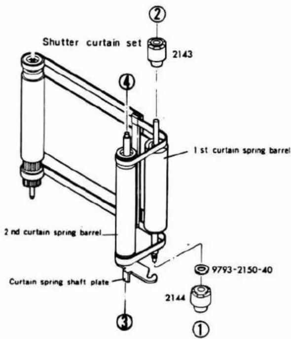
Fig. 1 2114 Spring setting
Fig. 2 2123 Spring setting
Fig. 3 2189 Spring setting
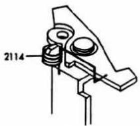
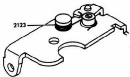
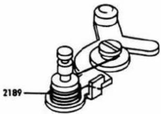
■ Charge gear A and First curtain shutter gear assembly procedure
- Align the mark of charge gear A (2105) to that of charge gear B (2104) as illustrated below.
- NOTE: After assembling charge gears, do not turn the gears. If the marks are not aligned to each other, under-or over-charge will occur.
- Then mount 1st curtain shutter gear (2106) in such a position that the projection on the back is in contact with the left side of stopper (2151) of shutter base plate.
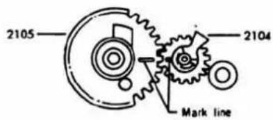
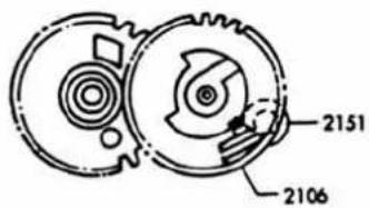
■ Second curtain spring barrel shaft checking, and Ratchet stop spring, Ratchet mounting
■ Checking for vertical looseness of 2 nd curtain spring barrel shaft.
Fit in curtain spring shaft stop plate (2128) of the 2nd curtain spring barrel shaft onto the 1st curtain spring barrel shaft, and then press down the 2nd curtain spring barrel in the direction of arrow to make curtain spring shaft stop plate (2128) tight on the shutter base plate. At that time, the 2nd curtain shaft should be projected 0\~0.2 mm from the shutter base plate.
- If the 2nd curtain shaft projection is not within 0\~0.2mm, check the shutter base plate.
■ Ratchet stop spring and ratchet mounting
Mount ratchet stop spring (2148) as illustrated below. Also attach 9793-1635-40, ratchet (2147). Then charge the spring to such an extent that the 1st and 2nd curtain ribbons do not slacken.
• The end of ratchet stop spring (2148) should be at the tooth bottom of ratchet (2147).
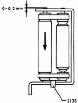
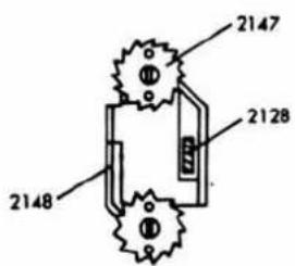
② Curtain shaft section·Second curtain shutter gear
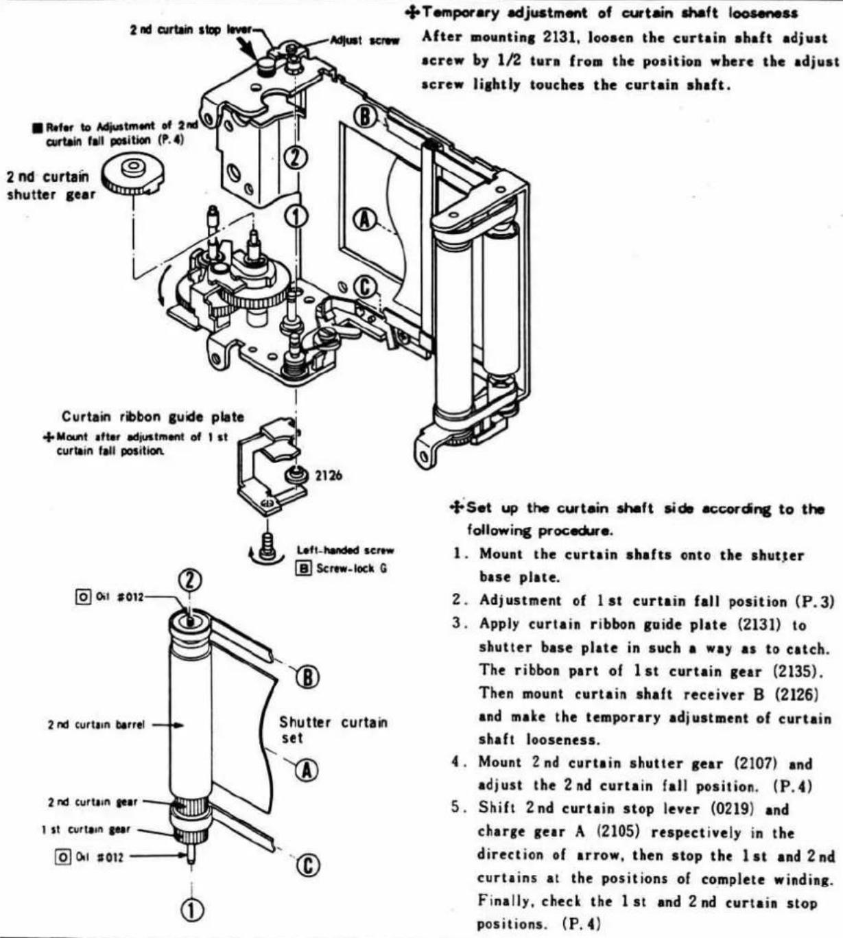
■ Adjustment of shutter curtain position
■Adjustment of shutter curtain position
- Shift 2nd curtain stop lever (0219) in the direction of arrow and turn 2nd curtain barrel (2129) to wind the 2nd curtain and then stop it at the center of picture frame.
- Turn 1st curtain gear (2135) in the direction of arrow and maintain the 1st curtain slit at the position as illustrated. Then turn 1st curtain shutter gear (2106) in the direction of arrow to let it contact the stopper of shutter base plate. Thus, engage 1st curtain gear (2135) with 1st curtain shutter gear (2106) and fit in curtain shaft receiver B (2126).
- CHECK: Turn charge gear A (2105) in the direction of arrow to operate the 1st curtain. Then the 1st curtain slit position should be as illustrated below.
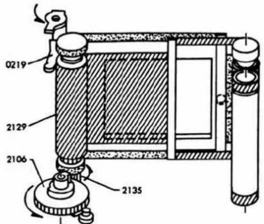
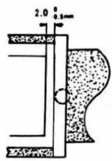
■Adjustment 2 nd curtain stop position
-
With the 2nd curtain stopped, turn 2nd curtain barrel (2129) in the direction of arrow and hold it when 2nd curtain stop lever (0219) is in contact with 2nd curtain barrel (2129) as illustrated below.
-
Fit in 2nd curtain shutter gear (2107) as illustrated, thus engaging it with the gear of 2nd curtain barrel (2129), set 2nd curtain stop lever (0219) free to turn 2nd curtain shutter gear (2107) in the direction of arrow until it stops on 1st curtain shutter gear (2106).
- CHECK: When 2nd curtain shutter gear (2107) is stopping on the 1st curtain shutter gear, curtain overlap should be within 2.5 ± 0.5 mm the 1st curtain slit position.
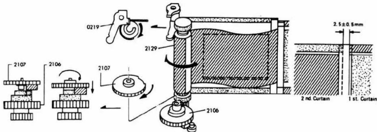
■1st and 2nd curtain stop position checking
-
With winding completed, the 1st curtain stop position should be within 1.5±0.5mm from the 2nd curtain slit position.
-
Shift 1st curtain stop lever (0212) to run the 1st curtain only. Then the 2nd curtain stop position should be within the range as illustrated.
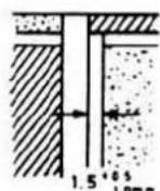
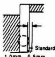
(Protrusion of 1 st curtain slit from picture frame should be less than 0.5 mm.)
③ Control base plate set·Trigger base plate
■After completing the procedure on this page, carry out LED mounting and lead wire soldering on Page.7, and performance adjustment.
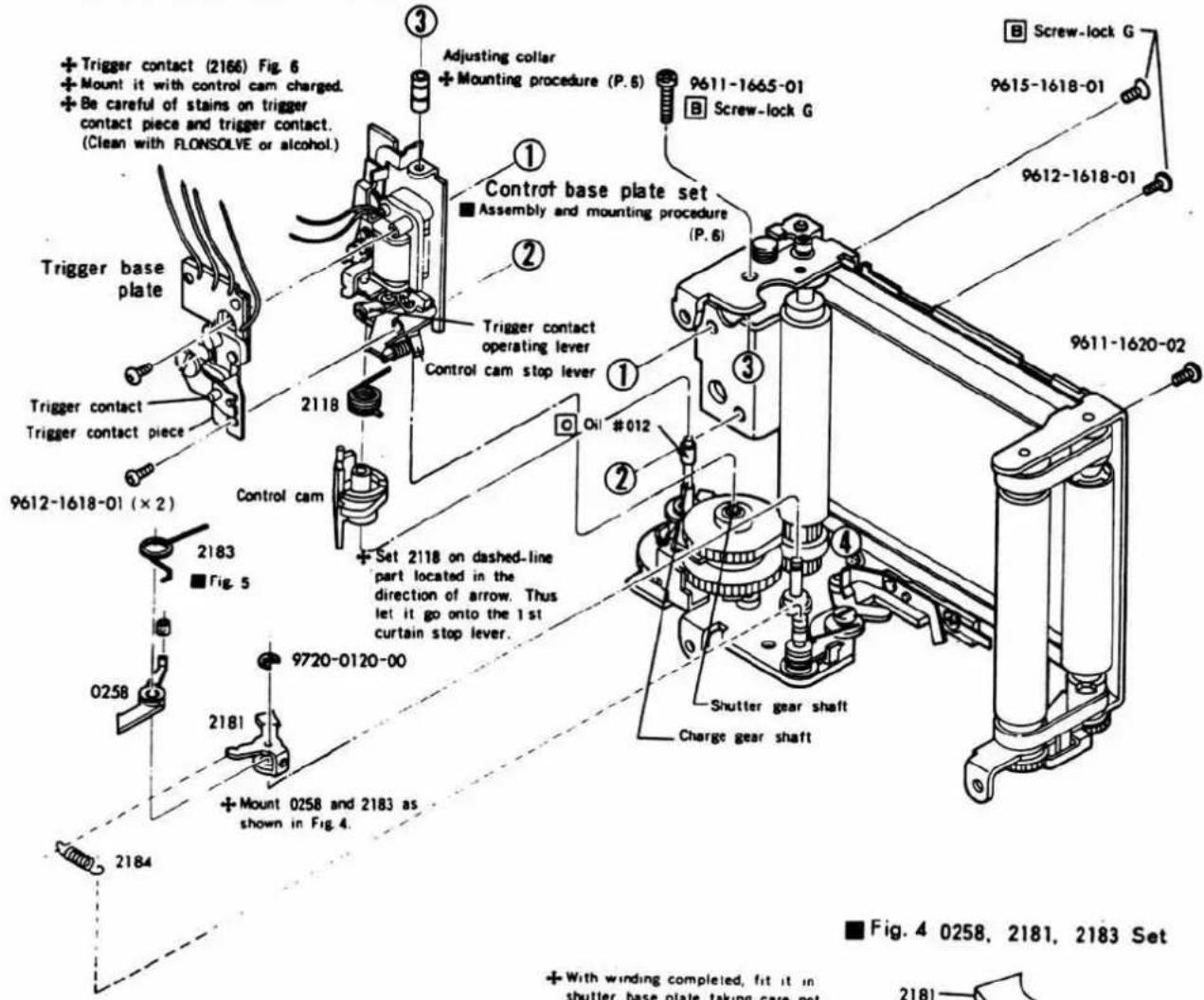
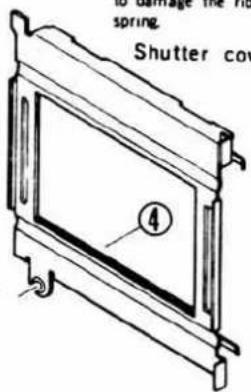
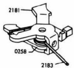
Fig. 6 2166 assembly
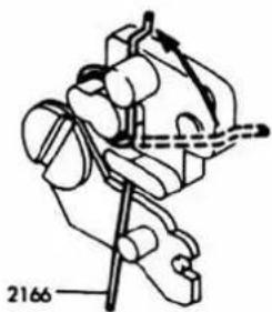
Fig. 5 2183 SP setting
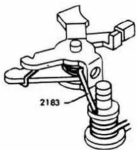
Control base plate assembly
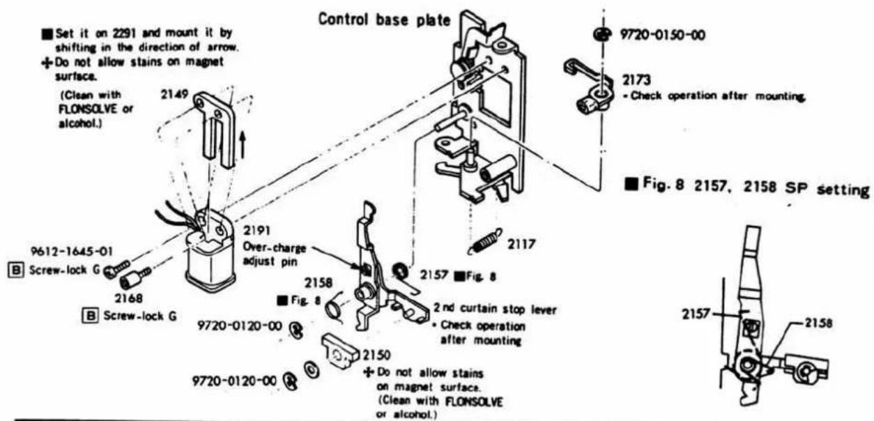
Control base set and adjusting collar mounting procedure
■Control base plate set mounting
Shift control cam stop lever (2115) in the direction of arrow and set control cam operation spring (2118) onto the control base plate. Then couple the projection of control cam (2109) with trigger contact operation lever (2173), bring 2nd curtain release operation lever (2160) to the left side of 2nd curtain stop lever (0219) and thus engage it with shutter gear shaft (2110) and charge gear shaft (2111).
■Adjusting collar mounting
Fit in collar setting jig (2006-2215-75) onto the shutter base plate, and mount the adjusting collar.
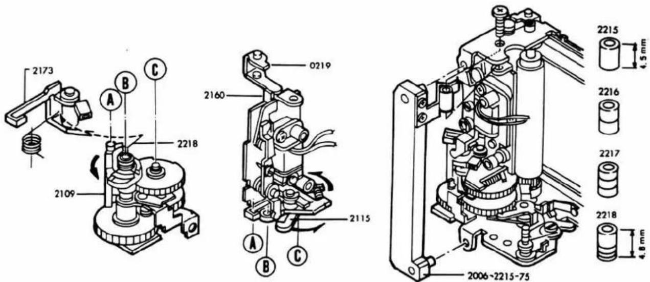
- After mounting, re-adjust the vertical looseness of curtain shaft to 0.1\~0.2mm by the adjust screw, and then apply screw-lock.
LED mounting and lead wire soldering
Solder the lead wires as illustrated below.
Solder brown lead wire after inserting it into circuit board.

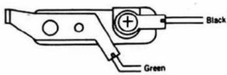
Shutter performance adjustment
■ Adjustment items
- Over-charge volume of magnet
- Curtain speeds
- Manual sec. time
- Curtain bound
- Synchro time lag
■ Temporary body (2006-0101-75) and shutter setting procedure
- Shift winding shaft receiver of temporary body in the direction of arrow beforehand. Position the eccentric screw (9281) of shutter charge gear D (0350) as illustrated below.
- Mount the shutter on the front frame of body and set up the front frame by shifting it towards the body winding side.
- Shift winding shaft receiver (0310) in the direction of arrow so that charge gear A (2105) is engaged with shutter charge gear C (3016) as illustrated below. Then tighten up the set-screw.
- Make the adjustment by eccentric screw (9281) so that sprocket idle gear (3034) completes winding with 1 tooth over-charged from control base plate (0202) when winding is done slowly and 2nd curtain stop lever (0219) is greatly moved in the direction of arrow.
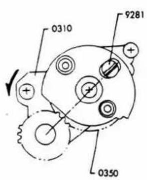
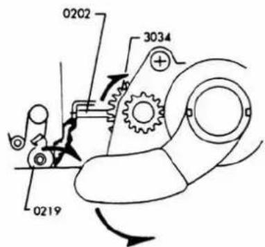
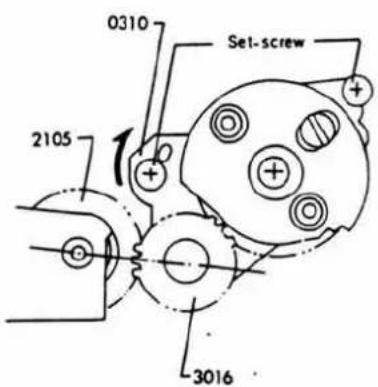
■Precautions for measurement
If high speed operation or speed change occurs when the shutter connected to the measuring instrument is released, release the shutter with the MEAS-CAL switch set to either "CAL" or "MEAS".
① Adjustment of magnet over-charge volume
■Measuring instrument: Camera standard tester (ST-5101)
Standard value: Over-charge volume 0.1\~0.2 mm
- Remove trigger base plate (0264) and charge the shutter to make shutter magnet (2150) tight on shutter magnet core (2149), hold it with finger, and release the shutter. Thus, make the adjustment with adjust pin (2154) so that the end of 2nd curtain release lever (0255) moves 0.1\~0.2 mm.
- Mount trigger base plate (0264) and connect the measuring instrument and shutter as illustrated below. Then make the setting of the tester as follows.
- Release the shutter and check for high speed operation. If so, turn adjust pin (2154) to reduce the over-charge volume under the condition in 1.
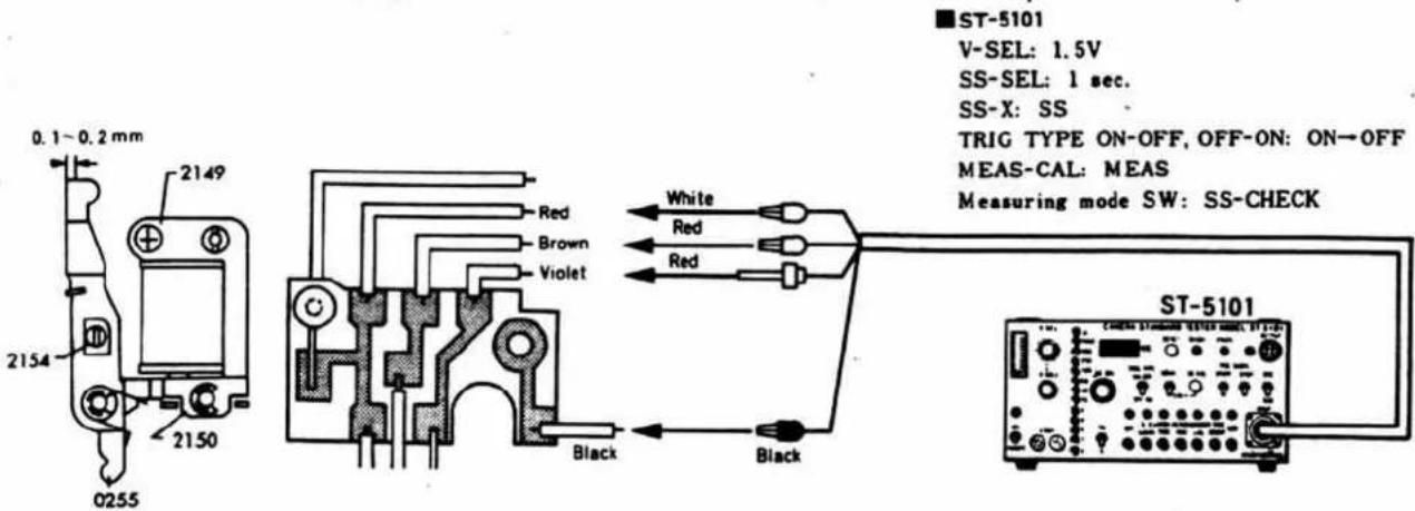
② Adjustment of curtain speeds
■Measuring instruments: Camera standard tester (ST-5101)
Shutter tester (FS1D-MN4·S-2101)
■ Standard valve: 10.7\~11.3ms both 1st and 2nd curtains.
- Connect the measuring instrument and shutter as illustrated below. Make the setting of the tester as follows.
- Set shutter tester to RUN-T, then release the shutter, and make the adjustment by ratchet (2147) so that both 1st and 2nd curtain speeds are 10.7\~11.3 ms.
- If curtain speeds cannot be adjusted because of high speed operation, open the shutter by turning trigger adjust plate (2213) in the direction of arrow.
- Set the shutter tester to EXP·T, then release the shutter. Make the re-adjustment so that the values of ranges A and C become equal to each other.
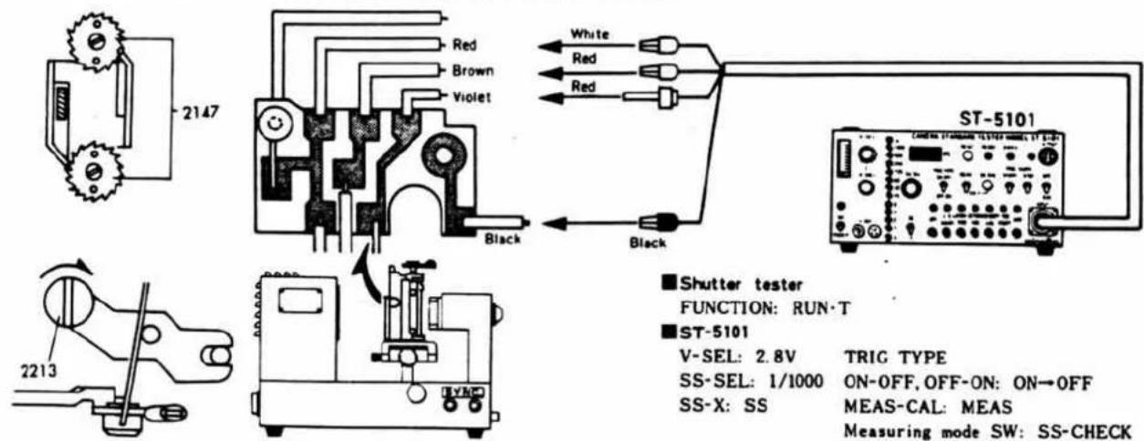
③ Adjustment of Manual sec. time
■Measuring instruments:
: Camera standard tester (ST-5101)
: Shutter tester (FS1D-MN4·S-2101)
- Connect the measuring instrument and shutter as illustrated below. Make the setting of the tester as follows.
- Set V-SEL switch of camera standard tester to 2.8V, SS-SEL switch to 1/1000, then release the shutter. Make that the indication of shutter tester is
- Set SS-SEL switch to 1/500, then release the shutter. Again make the adjustment by trigger adjust plate shaft (2213), keeping the balance with the result in 1/1000.
- Set SS-SEL switch to 1/60, 1/8, and 1, then release the shutter respectively. The measured values should be within the specifications.
- Set V-SEL switch to 1.85 V and SS-SEL switch to 1/1000, then release the shutter. The difference from the value obtained at 2.8 V should be within 0.4 ms.
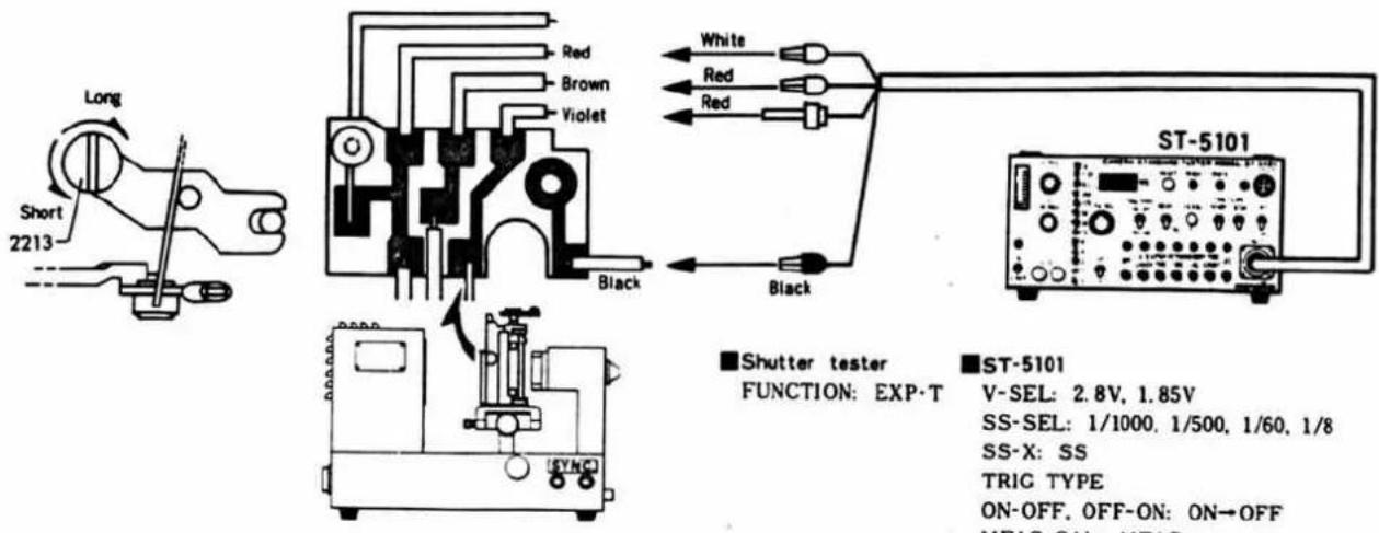
ST-5101
V-SEL: 2.8V, 1.85V
SS-SEL: 1/1000, 1/500, 1/60, 1/8
SS-X: SS
TRIC TYPE
ON-OFF. OFF-ON: ON→OFF
MEAS-CAL: MEAS
Measuring mode SW.: SS-CHECK
4 Adjustment of curtain bound
■Measuring instrument: Camera standard tester (ST-5101)
Shutter tester (FS1D-MN4·S-2101)
■Standard value: No bound in picture
- Connect the measuring instrument and shutter as illustrated right. Make the setting of the tester as follows.
- Release the shutter and check for curtain bound. If bound exists, adjust it by bending the brake spring of shutter cover (0203). Note that excessive bending will affect winding operation.
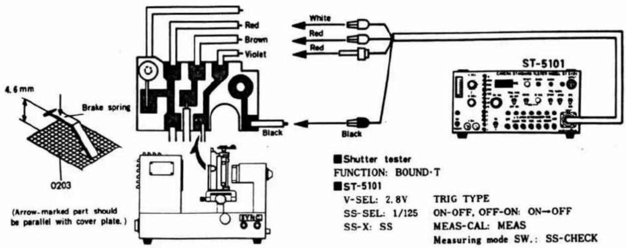
⑤ Adjustment of synchro time lag
■Measuring instruments
: Camera standard tester (ST-5101)
: Shutter tester (FS1D-MN4·S-2101)
Standard valve:
| Synchro contact | Allowable time lag | |
| X | Range A | 0.45~0.7 ms |
| Range B | 2.5 ms or less | |
- Connect the measuring instrument and shutter as illustrated below. Make the setting of the tester as follows.
- Release the shutter and make the adjustment by X lever stopper (2205) so that the measured value for range A is as specified. At that time, the measured value for range B should be within the specification.
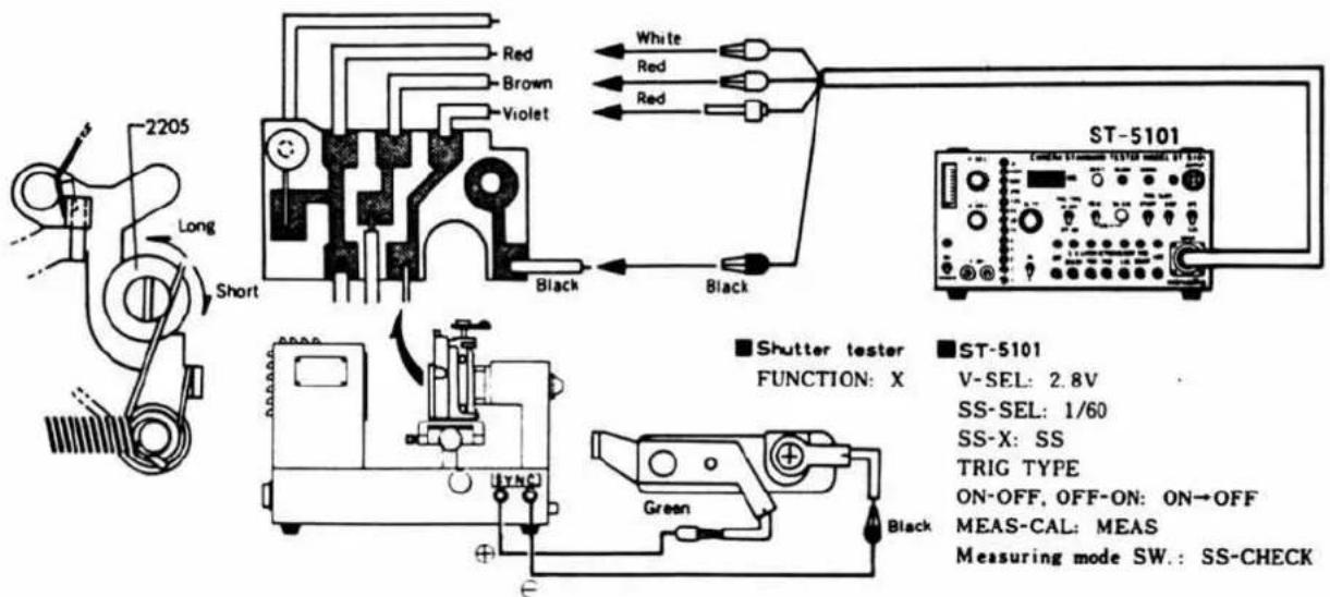
- MINOLTA XG7 2006-100(2006-200)
- MINOLTA XG2 2006-300(2006-400)
- MINOLTA XG-E 2006-500(2006-600)
- TYPE
- STANDARD LENS
- AE SYSTEM
- SHUTTER
- FILM FEED
- FINDER
- EXPOSURE CONTROL
- OTHERS
- EXCLUSIVE ACCESSORIES
- DIMENSIONS
- Description of Mechanism
- Winding Mechanism
- (Parts which require positioning)
- Winding Lever Operation
- Shutter Dial Mechanism
- 〈Operation〉
- Auto/Manual/Bulb changeover
- Film sensitivity setting
- Exposure correction
- Release switch
- Magnetic Release Mechanism
- 〈Return〉
- Magnetic Release Operation by Remote Cord
- Shutter Mechanism
- Charge mechanism
- Release mechanism
- X contact mechanism
- Mirror Box Mechanism
- Mirror (45°) retaining mechanism
- Mirror raising and lowering mechanism
- 〈Raising〉
- 〈Lowering〉
- Preset mechanism
- 〈Returning〉
- Principle of Metering and Description of Circuit
- Outline
- - Function
- - Composition
- General description
- - Metering system
- - Memory system
- - Metering switch
- • Automatic exposure control system
- Metering system
- Control system
- - Manual sec. time
- - Bulb mode
- - Strobe auto
- - Electronic SELF
- - Transistor switch
- Description of circuit
- Mode selector circuit
- Metering switch (Touch switch)
- Voltage detecting circuit
- Metering operation circuit
- Auto Mode:
- Manual Mode:
- Indication circuit
- Magnetic release
- Over-rang lock
- Memory circuit
- Bulb mode
- Magnetic SELF
- Remote-control
- Winder control function
- Strobo Auto
- XG Time Chart
- XG 7 (2006-100, -200) XG 2 (2006-300, -400) Parts List XG-E (2006-500, -600)
- Penta holder 1 (related to eyepiece modification)
- Penta holder 2 (related with fresnel modification)
- ペンタホルダー2(焦点板変更の関連)
- Penta holder 3 (related with penta. pressure modification)
- Disassembly, Assembly and Adjustment
- ■ Assembling/Adjustment Procedures Chart
- ① Strap ring · Light shielding packing
- ③ Spool·Winding base plate A set
- ■ Spool G set assembly
- Winding base plate A set assembly
- ■ Winding base plate A set assembly (Sprocket positioning)
- - Checking
- ■ Winding base plate B assembly
- ⑤ Winding base plate B set
- ■ Winding base plate B set assembly procedure
- ■ Winding operation timing checking
- ■ Reversing stop claw timing adjustment
- Winding claw and stop lever timing checking
- S4 (Reset SW.) ON-OFF checking
- Back cover assembly
- ⑥ Back cover·Rewinding axis receiver set
- ■ Film counter adjustment
- Mirror box I
- ⑧ Mirror box Ⅱ
- Front base plate
- Front base plate set Bayonet lens mount
- Preset lever position checking
- ■ Measuring instrument: Standard lens (50mm F 1.4)
- Aperture coupling ring
- ■ Measuring instruments: Circuit tester.
- ■ Mirror angle adjustment
- [1] Shutter·Magnetic release base plate
- ■ Magnetic release base plate assembly
- ■ Shutter assembly procedure
- Pentagon holder assembly
- Pentagon holder set·Front cover
- ■ Front cover mounting procedure
- Front base plate set mounting procedure
- Over-charge volume adjustment
- Charge lever mounting procedure
- Battery case set mounting procedure
- ■ Shutter dial base plate assembly
- ■ Flexible circuit board mounting procedure
- ■ AUTO exposure adjustment
- ① Measurement of CdS resistance value and selection of R_1 , R_2
- ■ Measuring instruments:
- ■ Measuring method
- ② Determination of R_4 -180 mA adjustment-
- ■ Adjustment procedure
- ③ Adjustment of VR₂ -AUTO Shutter speed adjustment-
- ■ Standard value: 32\~36ms
- Body and measuring instrument setting
- Adjustment of VR3 -Indication adjustment-
- Standard value:
- ■ Adjustment of slope
- ■ Manual sec. time adjustment
- AUTO exposure checking
- ■ Checking procedure
- Indicating LED checking and adjustment
- ■ Touch switch operation checking
- Over-range lock checking
- ■ Magnetic release minimum operation voltage and release lock voltage checking
- C lamp lighting voltage checking
- Indicating LED minimum lighting voltage checking
- Self-timer operation checking
- ■ Measuring procedure
- ■ Minimum operation voltage checking
- ■ Synchro time lag checking
- Strobe function checking
- ① Checks before completion of charge
- ② Checks on completion of charge
- Body back (B. B) adjustment
- Standard valve
- Finder back adjustment
- Top cover assembly
- Top cover Bottom cover Outer finish
- 2005-3310-75
- Shutter performance checking
- ■ Checking items
- ■ When checking before mounting body:
- ■ When checking after completion of body:
- ■ Precautions for measurement
- ① Magnetic attraction and magnetic piece over-range volume checking
- ② Curtain speed checking
- ③ Manual sec. time checking
- Minimum operation voltage checking
- Curtain bound checking
- ⑥ Synchro time lag checking
- Trouble Shooting Chart
- Hints on use of Trouble Shooting Chart
- Contents of Chart
- Precautions for Work
- How to use the Trouble Shooting Chart
- Battery capacity checking method
- Voltage at main check points of electric circuits
- Trouble Items
- Inspection Specification
- Shutter speed and uneven exposure
- Shutter Parts List for XG series
- Shutter Parts List Part II
- ■ Charge gear A and First curtain shutter gear assembly procedure
- ■ Second curtain spring barrel shaft checking, and Ratchet stop spring, Ratchet mounting
- ② Curtain shaft section·Second curtain shutter gear
- ■ Adjustment of shutter curtain position
- ■Adjustment of shutter curtain position
- ■Adjustment 2 nd curtain stop position
- ■1st and 2nd curtain stop position checking
- ③ Control base plate set·Trigger base plate
- Control base plate assembly
- Control base set and adjusting collar mounting procedure
- ■Control base plate set mounting
- ■Adjusting collar mounting
- LED mounting and lead wire soldering
- Shutter performance adjustment
- ■ Adjustment items
- ■ Temporary body (2006-0101-75) and shutter setting procedure
- ■Precautions for measurement
- ① Adjustment of magnet over-charge volume
- ② Adjustment of curtain speeds
- ③ Adjustment of Manual sec. time
- ■Measuring instruments:
- ST-5101
- Adjustment of curtain bound
- ⑤ Adjustment of synchro time lag
- ■Measuring instruments
Brand : MINOLTA
Model : XG E
Category : Video camera