
RXGW20SHA3 - Switch Generac - Free user manual and instructions
Find the device manual for free RXGW20SHA3 Generac in PDF.


| Product Type | Automatic Transfer Switch |
| Model | RXGW20SHA3 |
| Brand | Generac |
| Rated Current | 200 Amps |
| Voltage Rating | 240 VAC, 60 Hz |
| Phases | Single Phase |
| Wiring Configuration | 3-Wire (L1, L2, N, G) |
| Enclosure Type | NEMA 3R (Rainproof) |
| Dimensions (H x W x D) | 24 x 16 x 8 inches (approx.) |
| Weight | 45 lbs (approx.) |
| Service Disconnect | Integral 200A Main Breaker (optional) |
| Transfer Mechanism | Heavy-duty contactor or motorized switch |
| Transition Type | Open Transition (break-before-make) |
| Generator Compatibility | Generac home standby generators (200A max) |
| Control System | Load shedding and exercise control ready |
| Monitoring | Utility voltage and frequency sensing |
| Enclosure Material | Galvanized steel with powder coat finish |
| Operating Temperature Range | 20°F to 122°F (-6.7°C to 50°C) |
| Warranty | Limited 5 years (parts) |
| Certifications | UL listed to UL 1008 |
| Mounting | Wall-mounted (vertical) |
| Knockouts | Multiple for conduit entry (top, bottom, sides) |
| Maintenance | Annual inspection and exercise cycle |
Frequently Asked Questions - RXGW20SHA3 Generac
User questions about RXGW20SHA3 Generac
0 question about this device. Answer the ones you know or ask your own.
Ask a new question about this device
Download the instructions for your Switch in PDF format for free! Find your manual RXGW20SHA3 - Generac and take your electronic device back in hand. On this page are published all the documents necessary for the use of your device. RXGW20SHA3 by Generac.
USER MANUAL RXGW20SHA3 Generac
Automatic Transfer Switch
200 Amp, Single Phase, 240 VAC, Service Rated, 20–40 Circuit Load Center With Pass-Through Lugs
Model Number
RXGW20SHA3
natural_image
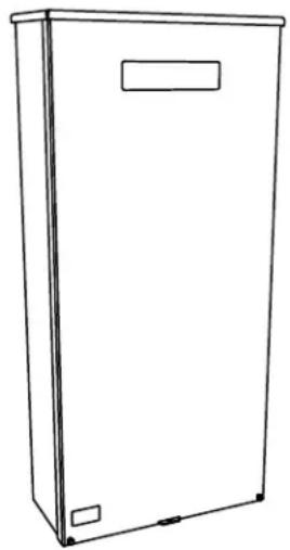
Line drawing of a rectangular enclosure with a label on top and bottom (no text or symbols)SERIAL NUMBER: ____
DATE PURCHASED: ____
WWW.GENERAC.COM
888-436-3722
Para español, visita: http://www.generac.com/service-support/product-support-lookup
Pour le français, visiter : http://www.generac.com/service-support/product-support-lookup
! WARNING
CANCER AND REPRODUCTIVE HARM
www.P65Warnings.ca.gov.
(000393a)
Table of Contents
Section 1: Safety Rules & General Information
Introduction ....1
Read This Manual Thoroughly ....1
Safety Rules ....1
General Hazards ....1
Electrical Hazards ......2
Section 2: Installation
Introduction to Installation ....5
Mounting the Enclosure ....5
Opening the Enclosure ....5
Installing Breakers 6
Installing Branch Circuit Conductors ....6
Connecting Power Source and Generator
Power Supply 6
Connecting Start Circuit Wires ....7
Connecting SACM 8
Control of Air Conditioner Load 8
Auxiliary Contact 9
Fault Current Identification Label ......9
Section 3: Operation
Functional Tests and Adjustments ....11
Manual Operation 11
Close to Utility Source Side 11
Close to Generator Source Side 12
Return to Utility Source Side 12
Voltage Checks 12
Utility Voltage Checks 12
Generator Voltage Checks 12
Generator Tests Under Load 12
Checking Automatic Operation ....13
Installation Summary ......13
Shutting Generator Down While
Under Load 13
Shutting Generator Down To Perform
Maintenance 14
Testing the SACM 14
Testing The SMM 14
Fuse Removal and Installation ....14
Section 4: Drawings and Diagrams
Installation Drawing 15
No. 10000047450 ....15
Interconnection Drawing 16
No. 10000047283—Page 1 of 4
(Liquid-Cooled Engine Generator) 16
No. 10000047283—Page 2 of 4
(Liquid-Cooled Engine Generator) 17
No. 10000047283—Page 3 of 4
(Air-Cooled Engine Generator) 18
No. 10000047283—Page 4 of 4
(Air-Cooled Engine Generator) 19
This page intentionally left blank.
Section 1: Safety Rules & General Information
Introduction
Thank you for purchasing a Generac Power Systems Inc. product. This unit has been designed to provide high performance, efficient operation, and years of use when maintained correctly.
The information in this manual is accurate based on products produced at the time of publication. The manu - facturer reserves the right to make technical updates, corrections, and product revisions at any time without notice.
Read This Manual Thoroughly

WARNING
Consult Manual. Read and understand manual completely before using product. Failure to completely understand manual and product could result in death or serious injury. (000100a)
If any section of this manual is not understood, contact the nearest Independent Authorized Service Dealer (IASD) or Generac Customer Service at 1-888-436-3722 (1-888-GENERAC), or visit www.generac.com for starting, operating, and servicing procedures. The owner is responsible for correct maintenance and safe use of the unit.
This manual must be used in conjunction with all other supporting product documentation supplied with the product.
SAVE THESE INSTRUCTIONS for future reference. This manual contains important instructions that must be followed during placement, operation, and maintenance of the unit and its components. Always supply this manual to any individual that will use this unit, and instruct them on how to correctly start, operate, and stop the unit in case of emergency.
Safety Rules
The manufacturer cannot anticipate every possible circumstance that might involve a hazard. The alerts in this manual, and on tags and decals affixed to the unit, are not all inclusive. If using a procedure, work method, or operating technique that the manufacturer does not specifically recommend, verify that it is safe for others and does not render the equipment unsafe.
Throughout this publication, and on tags and decals affixed to the unit, DANGER, WARNING, CAUTION, and NOTE blocks are used to alert personnel to special instructions about a particular operation that may be hazardous if performed incorrectly or carelessly. Observe them carefully. Alert definitions are as follows:
! DANGER
Indicates a hazardous situation which, if not avoided, will result in death or serious injury.
(000001)
WARNING
Indicates a hazardous situation which, if not avoided, could result in death or serious injury.
(000002)
CAUTION
Indicates a hazardous situation which, if not avoided, could result in minor or moderate injury.
(000003)
NOTE: Notes contain additional information important to a procedure and will be found within the regular text of this manual.
These safety alerts cannot eliminate the hazards that they indicate. Common sense and strict compliance with the special instructions while performing the action or service are essential to preventing accidents.
General Hazards
DANGER
Electrical backfeed. Use only approved switchgear to isolate generator from the normal power source. Failure to do so will result in death, serious injury, and equipment damage.
(000237)

DANGER
Electrocution. Do not wear jewelry while working on this equipment. Doing so will result in death or serious injury.
(000188)

! DANGER
Electrocution. Only authorized personnel should access transfer switch interior. Transfer switch doors should be kept closed and locked. Failure to do so will result in death or serious injury. (000213)
! DANGER
Automatic start-up. Disconnect utility power and render unit inoperable before working on unit. Failure to do so will result in death or serious injury. (000191)
! DANGER
Electrocution. In the event of electrical accident, immediately shut power OFF. Use non-conductive implements to free victim from live conductor. Apply first aid and get medical help. Failure to do so will result in death or serious injury. (000145)

WARNING
Loss of life. This product is not intended to be used in a critical life support application. Failure to adhere to this warning could result in death or serious injury. (000209b)
WARNING
Equipment damage. This unit is not intended for use as a prime power source. It is intended for use as an intermediate power supply in the event of temporary power outage only. Doing so could result in death, serious injury, and equipment damage. (000247a)
IMPORTANT NOTE: See individual unit specifications for required maintenance and run times pertaining to use.
- Competent, qualified personnel should install, operate, and service this equipment. Strictly comply to local, state, and national electrical and building codes. When using this equipment, comply with regulations established by the National Electrical Code (NEC), CSA Standard; the Occupational Safety and Health Administration (OSHA), or the local agency for workplace health and safety.
- If working on this equipment while standing on metal or concrete, place insulative mats over a dry wood platform. Work on this equipment only while standing on such insulative mats.
- Never work on this equipment while physically or mentally fatigued.
- Any voltage measurements should be performed with a meter that meets UL3111 safety standards, and meets or exceeds overvoltage class CAT III.
Electrical Hazards
DANGER
Electrocution. High voltage is present at transfer switch and terminals. Contact with live terminals will result in death or serious injury. (000129)

DANGER
Electrocution. Water contact with a power source, if not avoided, will result in death or serious injury.
(000104)

DANGER
Electrocution. In the event of electrical accident, immediately shut power OFF. Use non-conductive implements to free victim from live conductor. Apply first aid and get medical help. Failure to do so will result in death or serious injury. (000145)
! DANGER
Electrical backfeed. Use only approved switchgear to isolate generator from the normal power source. Failure to do so will result in death, serious injury, and equipment damage.
(000237)
DANGER
Electrocution, equipment and property damage. Handle transfer switches carefully when installing. Never install a damaged transfer switch. Doing so could result in death or serious injury, equipment and property damage. (000195)

! DANGER
Electrocution. Turn utility supply OFF before working on utility connections of the transfer switch. Failure to do so will result in death or serious injury. (000123)
! DANGER
Electrocution. Do not disable or modify the connection box door safety switch. Doing so will result in death or serious injury. (000157)
DANGER
Automatic start-up. Disconnect utility power and render unit inoperable before working on unit. Failure to do so will result in death or serious injury. (000191)
! DANGER
Equipment malfunction. Installing a dirty or damaged transfer switch will cause equipment malfunction and will result in death or serious injury.
(000119)
WARNING
Electric shock. Only a trained and licensed electrician should perform wiring and connections to unit. Failure to follow proper installation requirements could result in death, serious injury, and equipment or property damage.
(000155a)
CAUTION
Equipment damage. Verify all conductors are tightened to the factory specified torque value.
Failure to do so could result in damage to the switch base.
(000120)
CAUTION
Equipment damage. Perform functional tests in the exact order they are presented in the manual.
Failure to do so could result in equipment damage.
(000121)
CAUTION
Equipment damage. Exceeding rated voltage and current will damage the auxiliary contacts. Verify that voltage and current are within specification before energizing this equipment. (0001)
(000134a)
This page intentionally left blank.
Section 2: Installation
Introduction to Installation
This equipment has been wired and tested at the factory. Installing the transfer switch includes the following procedures:
- Mounting the enclosure.
- Connecting power source and load leads.
- Connecting generator start and sensing circuit.
- Connecting any auxiliary contact (if needed).
- Testing functions.
Mounting the Enclosure
! DANGER
Equipment malfunction. Installing a dirty or damaged transfer switch will cause equipment malfunction and will result in death or serious injury. (000119)
Mounting dimensions for the transfer switch enclosure are in this manual. Enclosures are typically wall-mounted. See Drawings and Diagrams.
This transfer switch is mounted in a UL type 3R enclosure. It can be mounted outside or inside and should be based on the layout of installation, convenience, and proximity to the utility supply and load center.
Install transfer switch as close as possible to electrical loads that will be connected to it. Mount transfer switch vertically to a rigid supporting structure. Level all mount - ing points to prevent transfer switch distortion. Use washers behind mounting holes to level the unit if necessary.
Opening the Enclosure
See Figure 2-1. First, remove outer cover (A):
- Remove two thumb screws (B).
- Slide slot (C) over retention tab.
- Lower cover until clear of top flange (D), and pull away from enclosure.
Then, remove inner panel (E):
- Loosen nut (F).
- Grasp inner panel at two cutouts (G—left and right). Tilt inner panel as shown, passing nut through t-slot (H) in inner panel.
- Lower inner panel until clear of two retention slots (J—left and right sides), and pull away from enclosure.

Figure 2-1. Open Enclosure
Installing Breakers
See Figure 2-2. Insert tab on each breaker (A) into the hook on the bus (B). Push breaker into bus until it snaps into place.
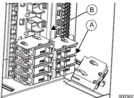
Figure 2-2. Install Breakers
NOTE: The following 1 in circuit breaker manufacturers are permitted to be installed: Siemens, Murray, Eaton BR, and Square D Homeline.
Installing Branch Circuit Conductors
- Install correctly sized branch circuit conductors into transfer switch. Knockouts can be made in the field as needed.
- Connect ungrounded branch circuit conductors (hot conductors) to a correctly sized circuit breaker approved for use with the transfer switch.
- Terminate neutral conductor and equipment grounding conductor of the branch circuit at neutral/equipment ground terminal bars.
- Size all conductors, raceways, conduits, and junction boxes, if required, to the applicable NEC code articles and follow NEC installation requirements for wiring method(s) selected.
NOTE: Multi-wire branch circuits must be installed in accordance with NEC Article 210.4.
Connecting Power Source and Generator Power Supply

DANGER
Electrocution. Turn utility and emergency power supplies to OFF before connecting power source and load lines. Failure to do so will result in death or serious injury. (000116)
CAUTION
Equipment damage. Verify all conductors are tightened to the factory specified torque value. Failure to do so could result in damage to the switch base. (000120)
Installation and interconnection diagrams are provided in this manual.
NOTE: All installations must comply with national, state, and local codes. It is the responsibility of the installer to perform an installation that will pass final electrical inspection.
- Connect utility supply at utility service disconnect circuit breaker terminals N1 and N2. Utility supply lugs are equipped with the 2017/2020 NEC required finger safe barriers. These barriers must remain in place after installation.
- Connect utility neutral conductor to grounded terminal bar. Neutral/grounding conductor terminal bars are bonded together and to the transfer switch enclosure through the use of a green main bonding jumper screw.
- Connect loads to integrated load center with customer-supplied circuit breakers.
- See Figure 2-1 and Figure 2-3. Connect generator to generator terminals (E1 and E2) on the transfer mechanism.

Figure 2-3. Wiring Connections
- Connect generator neutral wire to top neutral lug or side lugs on the panel board.
- Connect neutral conductors to the lugs and terminals along the neutral/ground bars in panel board section of transfer switch.
- Connect a maximum 200A subpanel feeder to lower T1 and T2 connections. Connect feeder neutral and equipment grounding conductors to the neutral/grounding terminal bar in the transfer switch.
- Connect grounding electrode conductors to neutral/ground terminal bars in panel board portion of transfer switch.
NOTE: A neutral to equipment ground main bonding screw (A) is provided for use where transfer switch is installed as service equipment.
Conductor sizes must be adequate to handle maximum current they will be subjected to, based on the 75 °C column of tables, charts, etc. used to size conductors. Installation must fully comply with all applicable codes, standards, and regulations.
All power cables can enter enclosure through provided knockouts. Additional knockouts into transfer switch can be made in the field as needed. Conduit entry shall maintain correct wire bending spaces required by Tables 312.6 (A) and (B) in the NEC. Conduits should be arranged to provide separation between utility and generator supply conductors inside the enclosure.
NOTE: If aluminum conductors are used, apply corrosion inhibitor to conductors. After tightening terminal lugs, carefully wipe away any excess corrosion inhibitor.
Tighten terminal lugs to required torque values as noted on decal located on the inside of the door. After tightening terminal lugs, carefully wipe away any excess corrosion inhibitor.
Connecting Start Circuit Wires
Control system interconnections consist of N1, N2, and T1, and leads 23, 194, and 9 (ground). The connections are color coded on the load shed to match connections in the Generac genset. Generac Type TC-ER-JP tray cable includes power cables with all necessary color-coded control wiring. It is suitable for direct burial, overhead, and indoor wiring.
NOTE: See Article 336 in the 2017 and 2020 editions of the NEC for more information on the installation requirements for Type TC-ER-JP cable.
The generator control wiring is a Class 1 signaling circuit. See instruction manual of specific engine generator for wiring connection details. Recommended wire gauge sizes for this wiring depends on wire length, as recommended in the following chart:
| Maximum Wire Length | Recommended Wire Size |
| 1–115 ft (1–35 m) | No. 18 AWG |
| 116–185 ft (36–56 m) | No. 16 AWG |
| 186–295 ft (57–89 m) | No. 14 AWG |
| 296–460 ft (90–140 m) | No. 12 AWG |
Exception: Conductors of AC and DC circuits, rated 1000 volts nominal or less, shall be permitted to occupy the same equipment, cable, or conduit. All conductors shall have an insulation rating equal to at least the maximum circuit voltage applied to any conductor within the equipment, cable, or conduit. See NEC 300.3(C)(1).
Connecting SACM
See Figure 2-4. The SACM can control an air conditioner (24 VAC) directly.
Control of Air Conditioner Load
- Route thermostat cable (from furnace/thermostat to outdoor air conditioner unit) to transfer switch.
-
Con nect wire to the terminal strip terminals (A/C 1) on SACM as shown in Figure 2-4. These are normally closed contacts which open upon load shed conditions. Route thermostat wire away from high voltage wires.
-
If required, connect additional air conditioners to the terminal strip terminals (A/C 2-4).
| Contact Ratings | |
| A/C 1-4 24 VAC, | 1.0 amp max |
NOTE: These instructions are for a typical air conditioner installation. Control of certain heat pumps and 2-stage air conditioners may require special connections or the use of SMMs to control the loads.

Figure 2-4. Typical SACM Connections
Auxiliary Contact
CAUTION
Equipment damage. Exceeding rated voltage and current will damage the auxiliary contacts. Verify that voltage and current are within specification before energizing this equipment. (000134a)
See Figure 2-5. If desired, there is one normally-closed auxiliary contact (A) on the transfer switch to operate customer accessories, remote advisory lights, or remote annunciator devices. A suitable power source must be connected to common terminal. If needed, an extra auxiliary contact can be added.
The auxiliary contact is normally closed when transfer switch is in utility mode. Contacts will open when transfer switch is in standby mode.
NOTE: Auxiliary contact is rated 10 amps at 125 or 250 volts AC, and 0.6 amps at 125 volts DC.

Figure 2-5. Auxiliary Contact
Fault Current Identification Label
See Figure 2-6. A Fault Current Identification Label is provided in the bag containing the unit owner's manual and transfer switch manual operating handle. The 2017 NEC requires the short-circuit current rating of the transfer equipment, based on type of overcurrent protective device protecting transfer equipment, be field marked on the exterior of the transfer equipment. For NEC compliance, verify required short-circuit current rating of transfer switch before installation. The completed label provides the local Authority Having Jurisdiction (AHJ) with information they may require during inspection.
Apply label to the exterior of the transfer switch enclosure. Use a pen to fill in required information, and then cover label with the clear protective decal.
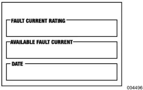
Figure 2-6. Fault Current Identification Label
NOTE: The 2020 NEC code change omits this field labeling requirement for one- and two-family dwelling units.
This page intentionally left blank.
Section 3: Operation
Functional Tests and Adjustments
CAUTION
Equipment damage. Perform functional tests in the exact order they are presented in the manual.
Failure to do so could result in equipment damage.
(000121)
Following transfer switch installation and interconnection, inspect entire installation carefully. A competent, qualified electrician should inspect it. The installation should strictly comply with all applicable codes, standards, and regulations. When absolutely certain installation is correct, complete a functional test of the system.
IMPORTANT NOTE: Before proceeding with functional tests, read and verify all instructions and information in this section is understood. Also read information and instructions of labels and decals affixed to transfer switch. Note any options or accessories that might be installed and review their operation.
Manual Operation

DANGER
Electrocution. Do not manually transfer under load. Disconnect transfer switch from all power sources prior to manual transfer. Failure to do so will result in death or serious injury, and equipment damage.
(000132)
CAUTION
Equipment damage. Do not use excessive force while manually operating the transfer switch. Doing so could result in equipment damage.
(000122)
See Figure 3-1. A manual handle (B) is shipped with the transfer switch manual. Manual operation must be verified BEFORE transfer switch is operated electrically. Proceed as follows to verify manual operation:
- Verify generator is in OFF mode.
- Turn off both utility (service disconnect circuit breaker) and emergency (generator main line circuit breaker) power supplies to transfer switch.
-
Note position of transfer mechanism main contacts (A) by observing the movable contact carrier arm. This can be viewed through the long narrow slot in the inside cover. The top of the movable contact carrier arm is yellow to be easily identified.
-
Manual operation handle in UP position—LOAD terminals (T1, T2) are connected to utility terminals (N1, N2).
- Manual operation handle in DOWN position-LOAD terminals (T1, T2) are connected to EMERGENCY terminals (E1, E2).
Close to Utility Source Side
Before proceeding, verify position of transfer switch by observing position of manual operation handle in Figure 3-1. If manual operation handle is UP, contacts are closed in utility (normal) position. No further action is required. If manual operation handle is DOWN, proceed with Step 1.
- With manual operation handle inserted into movable contact carrier arm, move handle UP. Hold on to manual operation handle as it will move quickly after the center of travel.
- Remove manual operating handle from movable contact carrier arm. Return manual operation handle to storage bracket.

Figure 3-1. Manual Operation
Close to Generator Source Side
Before proceeding, verify position of transfer switch by observing the position of the manual operation handle in Figure 3-1. If manual operation handle is DOWN, contacts are closed in generator (standby) position. No further action is required. If manual operation handle is UP, proceed with Step 1.
- With manual operation handle inserted into movable contact carrier arm, move manual operation handle DOWN. Hold on to manual operation handle as it will move quickly after the center of travel.
- Rem ove manual operating handle from movable contact carrier arm. Return manual operation handle to storage bracket.
Return to Utility Source Side
Proceed as follows to return to utility source side:
- Ma nually actuate transfer switch to return manual operating handle to the UP position.
- Rem ove manual operating handle from movable contact carrier arm. Return manual operation handle to storage bracket.
Voltage Checks
NOTE: Use the Digital Multimeter (DMM) LowZ low input impedance setting to collect accurate voltage measurements. LowZ eliminates the possibility of inaccurate ghost voltage readings, also known as phantom voltage or stray voltage readings. See DMM manufacturer's literature for additional information.
Utility Voltage Checks

DANGER
Electrocution. High voltage is present at transfer switch and terminals. Contact with live terminals will result in death or serious injury. (000129)

! DANGER
Electrocution. Turn utility supply OFF before working on utility connections of the transfer switch. Failure to do so will result in death or serious injury. (000123)
Proceed as follows to check utility voltage:
- T urn on utility power supply to transfer switch using utility service disconnect circuit breaker.
- With an accurate AC voltmeter, check for correct voltage. Measure across ATS terminal lugs N1 and N2; N1 to NEUTRAL and N2 to NEUTRAL.
Generator Voltage Checks

! DANGER
Electrocution. High voltage is present at transfer switch and terminals. Contact with live terminals will result in death or serious injury. (000129)
Proceed as follows to check generator voltage:
- Select MANUAL mode on generator panel. Generator will crank and start.
- Allow generator to stabilize and warm up at no-load for at least five minutes.
- Set generator's main circuit breaker (CB1) to ON (CLOSED).
- Verify no-load, voltage, and frequency with an accurate AC voltmeter and frequency meter. Measure across ATS terminal lugs E1 to E2; E1 to NEUTRAL and E2 to NEUTRAL.
| Frequency | 60–62 Hz |
| Terminals E1 to E2 | 240–246 VAC |
| Terminals E1 to NEUTRAL | 120–123 VAC |
| Terminals E2 to NEUTRAL | 120–123 VAC |
- Turn off generator supply to transfer switch when generator supply voltage is correct and compatible with transfer switch ratings.
- Set generator main circuit breaker (CB1) to OFF (OPEN).
- Pre ss OFF on generator panel to shut down generator.
IMPORTANT NOTE: DO NOT proceed until generator AC output voltage and frequency are correct and within stated limits. If no-load voltage is correct but no-load frequency is incorrect, engine governed speed may require adjustment. If no-load frequency is correct but voltage is not, voltage regulator may require adjustment.
Generator Tests Under Load
Proceed as follows to perform generator tests under load:
- Set generator main line circuit breaker (MLCB) to OFF (OPEN).
- Set utility service disconnect circuit breaker of the transfer switch to OFF (OPEN), and turn OFF (OPEN) all load circuit breakers.
- Ma nually actuate transfer switch main contacts to emergency (STANDBY) position. See Manual Operation.
-
Select MANUAL mode to start the generator. Allow engine to stabilize for a few minutes, and close lid.
-
Set generator MLCB to ON (CLOSED). Generator now powers all LOAD circuits. Verify generator operation under load as follows:
-
Turn on electrical loads to the full rated wattage/amperage capacity of generator. DO NOT OVERLOAD.
- With maximum rated load applied, check voltage and frequency across transfer switch terminals E1 and E2. Voltage should be greater than 230 VAC (240 VAC system); should be greater than 59 Hz.
- Verify fuel pressure remains within acceptable parameters (see generator installation manual).
-
Allow generator to run under rated load for at least 30 minutes. With unit running, inspect for unusual noises, vibration, or overheating that might indicate a problem.
-
Set generator MLCB to OFF (OPEN) when test under load is complete.
-
Allow generator to run at no-load for several minutes. Then, shut down generator by pressing OFF.
- Set main switch contacts to utility.
NOTE: See Manual Operation. Handle and operating lever of transfer switch should be in down position.
- Set utility service disconnect circuit breaker of transfer switch to ON (CLOSED).
System is now set for fully automatic operation.
Checking Automatic Operation
Proceed as follows to check system for correct automatic operation:
- Verify generator is in OFF mode.
-
Set utility service disconnect circuit breaker of the transfer switch to OFF (OPEN).
-
Verify switch is de-energized.
-
Install front cover of transfer switch.
-
Set transfer switch utility service disconnect circuit breaker to ON (CLOSED).
-
Set generator MLCB to ON.
-
Select AUTO on generator control panel. System is now ready for automatic operation.
-
Set transfer switch utility service disconnect circuit breaker to OFF (OPEN).
With generator ready for automatic operation, engine should crank and start when utility source power is turned off after a five second delay (factory default setting). After starting, transfer switch should connect load circuits to standby side after a five second delay. Allow system to operate through entire automatic sequence of operation.
With generator running and loads powered by generator AC output, set transfer switch utility service disconnect circuit breaker to ON (CLOSED). The following will occur:
- After approximately 15 seconds, transfer switch will transfer loads to utility power source.
- Approximately one minute after transfer, generator should shut down.
With generator in AUTOMATIC mode, system is now set for fully automatic operation.
frequency
Installation Summary
- Verify installation has been performed correctly as outlined by the manufacturer and that it meets all applicable laws and codes.
- Test and verify correct operation of the system as outlined in the appropriate installation and owner's manuals.
- Educate end-user on correct operation, maintenance, and service call procedures.
NOTE: The utility power circuit breaker in transfer switch must be turned OFF to simulate a utility outage. Shutting off main disconnect in a subpanel connected to transfer switch will NOT simulate an outage.
Shutting Generator Down While Under Load
IMPORTANT NOTE: To avoid equipment damage, follow these steps, in order, when shutting the generator down during utility outages. Shutdowns may be required during outages to perform routine maintenance or to conserve fuel.
To turn generator OFF (while running in AUTO and online):
- Turn main utility disconnect off.
- Turn generator MLCB (generator disconnect) to OFF (OPEN).
- Run generator for approximately one minute to cool down.
- Turn generator OFF.
To turn generator back ON:
- Put generator into AUTO mode. Start generator and warm-up for a few minutes.
- Set MLCB (generator disconnect) to ON (CLOSED).
The system now operates in AUTO mode. The main utility disconnect can be turned ON (CLOSED). To shut unit off, repeat this complete process.
Shutting Generator Down To Perform Maintenance
Proceed as follows to shut down generator for maintenance:
- Press OFF button on controller.
- Turn main utility disconnect OFF (OPEN).
- Turn MLCB (generator disconnect) on generator to OFF (OPEN) and follow maintenance procedure(s).
To turn generator back ON:
- Turn main utility disconnect ON (CLOSED).
- Put generator into AUTO mode.
- Set MLCB (generator disconnect) on generator to ON (CLOSED).
The system is now in AUTO mode.
Testing the SACM
A TEST pushbutton is provided on top of the SACM to test operation of load shed functions. The TEST button will work when ATS is in utility or generator position. Proceed as follows to test the SACM:
- Turn on utility supply to ATS.
- Verify managed loads are powered and all LEDs illuminate on SACM.
- Press TEST button on the SACM.
-
Verify all of the connected loads to be "shed" are disabled.
-
After five minutes, verify A/C 1 is energized and Status LED A/C 1 is ON.
-
After another 15 seconds, verify A/C 2 is energized and Status LED A/C 2 is ON.
-
After another 15 seconds, verify Load A/C 3 is energized and Status LED Load A/C 3 is ON.
-
After another 15 seconds, verify A/C 4 is energized and Status LED A/C 4 is ON.
Testing The SMM
See SMM owner's/installation manual for testing procedure.
Fuse Removal and Installation
See Figure 3-2. A fuse removal and installation tool (A) is included in the control housing.

Figure 3-2. Fuse Removal and Installation Tool
If a fuse requires replacement, snap tool free with an appropriate tool such as diagonal pliers, and use it to replace fuse. The tool can be stored in the control housing retainer directly above the fuses, with the large thumb tab facing out.
Use only Generac replacement fuses—part number 100000005117, rated 240 VAC, 6.3 Amps, 10,000 AIC. Alternative fuses are Littelfuse ^® 021606.3MXHP or Optifuse ^® FCD-6.3.
Section 4: Drawings and Diagrams
Installation Drawing
No. 10000047450
![Ø8 [3] 7 [3] Ø14 [6] DETAIL A SCALE 0.800](/content/2026/05/998997/images/dbb26bec22ddbf97bf26b9e8789d5223a7ab07271c0db54d0afac630b57915b0.jpg)
![204 [8.0]](/content/2026/05/998997/images/a39d806a9ddf2879b5b210bc117f6d91922766a2e868c73e8e0ad1f7e8c1d414.jpg)
![SEE DETAIL A 448 [17.6] 356 [14.0] 38 [15] 889 [35.0] 45 [18] 979 [38.5]](/content/2026/05/998997/images/dbbe2b734d2e1cb04a80cc3d3f1b189ff9d07372cae0676b3ba01c12dc06fcd4.jpg)
Interconnection Drawing
No. 10000047283—Page 1 of 4 (Liquid-Cooled Engine Generator)

No. 10000047283—Page 2 of 4 (Liquid-Cooled Engine Generator)

No. 10000047283—Page 3 of 4 (Air-Cooled Engine Generator)

No. 10000047283—Page 4 of 4 (Air-Cooled Engine Generator)

This page intentionally left blank.
This page intentionally left blank.
This page intentionally left blank.
Part No. A0000023930 Rev B 06/27/19
©2019 Generac Power Systems, Inc.
All rights reserved.
Specifications are subject to change without notice.
No reproduction allowed in any form without prior written
consent from Generac Power Systems, Inc.
GENERAC®
Generac Power Systems, Inc.
S45 W29290 Hwy. 59
Waukesha, WI 53189
1-888-GENERAC (1-888-436-3722)
www.generac.com
- Automatic Transfer Switch
- ! WARNING
- CANCER AND REPRODUCTIVE HARM
- Table of Contents
- Section 1: Safety Rules & General Information
- Section 2: Installation
- Section 3: Operation
- Section 4: Drawings and Diagrams
- Introduction
- Read This Manual Thoroughly
- WARNING
- Safety Rules
- ! DANGER
- CAUTION
- General Hazards
- DANGER
- IMPORTANT NOTE: See individual unit specifications for required maintenance and run times pertaining to use.
- Electrical Hazards
- Introduction to Installation
- Mounting the Enclosure
- Opening the Enclosure
- Installing Breakers
- Installing Branch Circuit Conductors
- Connecting Power Source and Generator Power Supply
- Connecting Start Circuit Wires
- Connecting SACM
- Control of Air Conditioner Load
- Auxiliary Contact
- Fault Current Identification Label
- This page intentionally left blank.
- Functional Tests and Adjustments
- Manual Operation
- Close to Utility Source Side
- Close to Generator Source Side
- Return to Utility Source Side
- Voltage Checks
- Utility Voltage Checks
- Generator Voltage Checks
- Generator Tests Under Load
- Checking Automatic Operation
- Installation Summary
- Shutting Generator Down While Under Load
- Shutting Generator Down To Perform Maintenance
- Testing the SACM
- Testing The SMM
- Fuse Removal and Installation
- Installation Drawing
- Interconnection Drawing
Brand : Generac
Model : RXGW20SHA3
Category : Switch