SPX1000X5 - Receiver Stinger - Free user manual and instructions
Find the device manual for free SPX1000X5 Stinger in PDF.


| Product Type | 5-Channel Power Amplifier |
| Model | SPX1000X5 |
| Brand | Stinger |
| RMS Power (14.4Vdc, ≤1% THD) | 95W x 4 @ 4Ω (CH 1-4) 275W x 1 @ 4Ω (CH 5) 150W x 4 @ 2Ω (CH 1-4) 500W x 1 @ 2Ω (CH 5) |
| Frequency Response | ±1dB from 20Hz to 20kHz |
| Signal-to-Noise Ratio | >110dB |
| Input Range | 200mV to 12V |
| Typical Efficiency | 80% |
| Damping Factor | >200 |
| Lowest Recommended Load | 4Ω Bridged or 2Ω Stereo |
| Recommended Fuse Size | 80 Amp |
| Power/Ground Wire Size | 8 Gauge |
| Dimensions (L x W x H) | 215mm x 130mm x 41mm (8.5" x 5.11" x 1.6") |
| Crossover Types | High-Pass, Low-Pass (12dB/octave, 40-400Hz) Subsonic Filter (10-55Hz) Subwoofer Low-Pass (50-250Hz) |
| Remote Level Control | Included, with mute function; ±20dB adjustment |
| Phase Control | Variable 0°-180° (Sub channel) |
| Bass Boost | 0-18dB (Sub channel) |
| Weather Resistance | Marine and Power Sports rated |
| Amplifier Topology | Class D (efficient) |
| Protection Features | Thermal shutdown, short circuit protection (LED indicator) |
| Warranty | 1 year limited (US only; international via local reseller) |
Frequently Asked Questions - SPX1000X5 Stinger
User questions about SPX1000X5 Stinger
0 question about this device. Answer the ones you know or ask your own.
Ask a new question about this device
Download the instructions for your Receiver in PDF format for free! Find your manual SPX1000X5 - Stinger and take your electronic device back in hand. On this page are published all the documents necessary for the use of your device. SPX1000X5 by Stinger.
USER MANUAL SPX1000X5 Stinger
natural_image
Front view of a Siemens SIMRex network switch device with ports and connectors (no readable text or symbols beyond branding)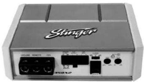
natural_image
Front view of a device labeled 'Svanger' with ports and indicators (no readable text beyond branding)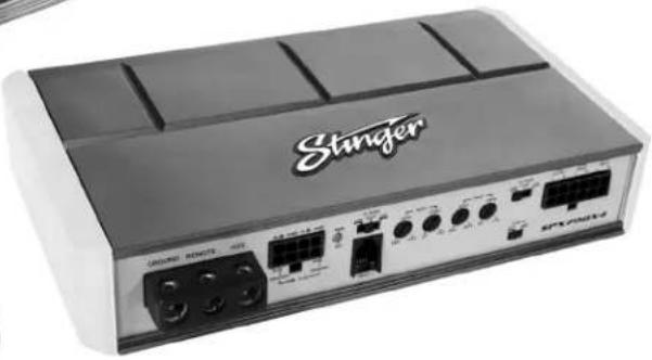
natural_image
Front view of a Stinger audio device with visible ports and buttons (no readable text beyond branding)SPX350X2 / SPX700X4 / SPX1000X5
Amplifier Manual
• RCA or High Level Signal Input
• Weather Resistant for Marine and Power Sports
• Ultra Compact Chassis
• High and Low Pass Crossovers
- Direct Insert Power Terminals
- Remote Volume Control with Mute Included
• Efficient Class D Topology
Características
2 Channel Power Amplifier
Specifications
Frequency Response: ± 1dB from 20Hz to 20kHz
Signal to Noise Ratio: >110dB
High and Low Pass Crossovers: 12dB per Octave
Low Pass Crossover Range: 40Hz to 400Hz
High Pass Crossover Range: 40Hz to 400Hz
Input Range: 200 millivolts to 12 volts
Typical Efficiency: 80%
Damping Factor: Greater than 200
RMS Power (14.4Vdc ≤ 1% THD):
125 x 2 @ 4 ohm Stereo
175 x 2 @ 2 ohm Stereo
350 x 1 @ 4 ohm Bridged
Lowest Recommended Load:
4 ohm Bridged or 2 ohm Stereo
Recommended Fuse Size: 30 amp
Power/Ground Wire Size: 8 Gauge
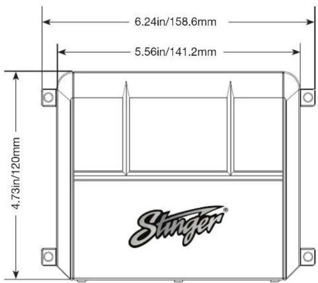
Dimensions: 141mm L x 120mm W x 41mm H
5.56" L × 4.73" W × 1.6" H
Specifications
SPX700X4
4 Channel Power Amplifier
Frequency Response: ±1dB from 20Hz to 20kHz
Signal to Noise Ratio: >110dB
High and Low Pass Crossovers: 12dB per Octave
Low Pass Crossover Range: 40Hz to 400Hz
High Pass Crossover Range: 40Hz to 400Hz
Input Range: 200 millivolts to 12 volts
Typical Efficiency: 80%
Damping Factor: Greater than 200
Recommended Fuse Size: 60 amp
Power/Ground Wire Size: 8 Gauge
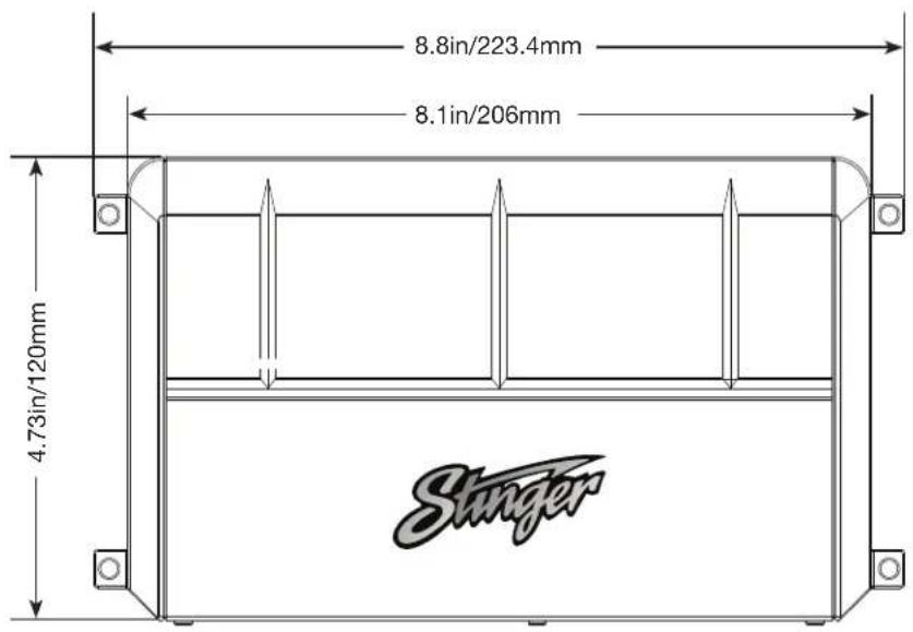
Dimensions: 206mm L x 120mm W x 41mm H
8.1" L × 4.73" W × 1.6" H
RMS Power (14.4Vdc ≤ 1% THD):
125 x 4 @ 4 ohm Stereo
175 x 4 @ 2 ohm Stereo
125 x 2 @ 4 ohm Stereo +
350 x 1 @ 4 ohm Bridged*
(Rear Channels only)
Lowest Recommended Load:
4 ohm Bridged* or 2 ohm Stereo
*Only Rear Channels controlled by Remote Level Knob.

SPX1000X5
5 Channel Power Amplifier
Specifications
Frequency Response: ±1dB from 20Hz to 20kHz
Signal to Noise Ratio: >110dB
High and Low Pass Crossovers: 12dB per Octave
Low Pass Crossover Range: 40Hz to 400Hz
High Pass Crossover Range: 40Hz to 400Hz
Sub Crossover Range: 50Hz to 250Hz
Input Range: 200 millivolts to 12 volts
Typical Efficiency: 80%
Damping Factor: Greater than 200
RMS Power (14.4Vdc ≤ 1% THD):
95 x 4 @ 4 ohm Stereo - CH 1-4
275×1 @ 4 ohm - CH 5
150 x 4 @ 2 ohm Stereo - CH 1-4
500 x 1 @ 2 ohm - CH 5
Lowest Recommended Load:
4 ohm Bridged or 2 ohm Stereo
Recommended Fuse Size: 80 amp
Power/Ground Wire Size: 8 Gauge
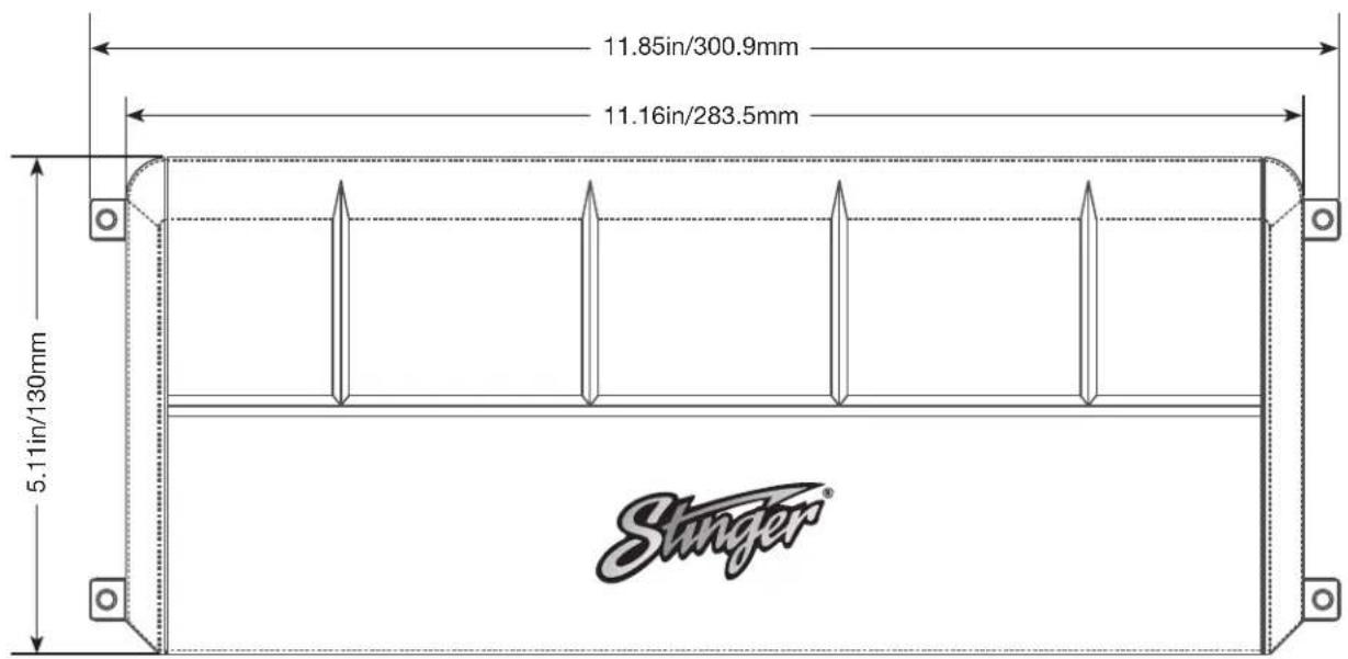
Dimensions: 215mm L x 130mm W x 41mm H
8.5" L x 5.11" W x 1.6" H

Connections / Settings
SPX350X2
2 Channel Power Amplifier
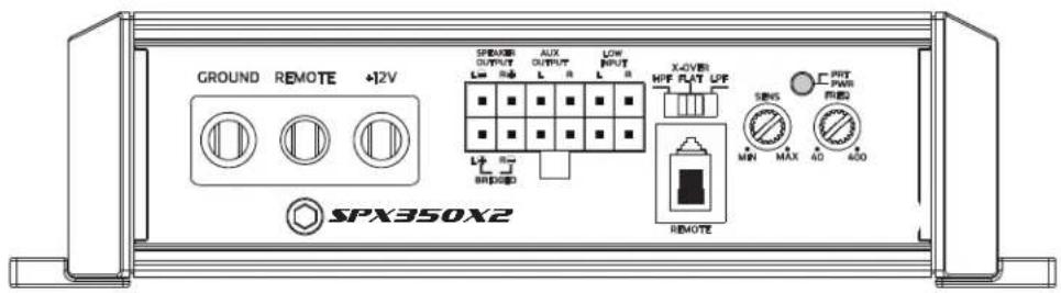
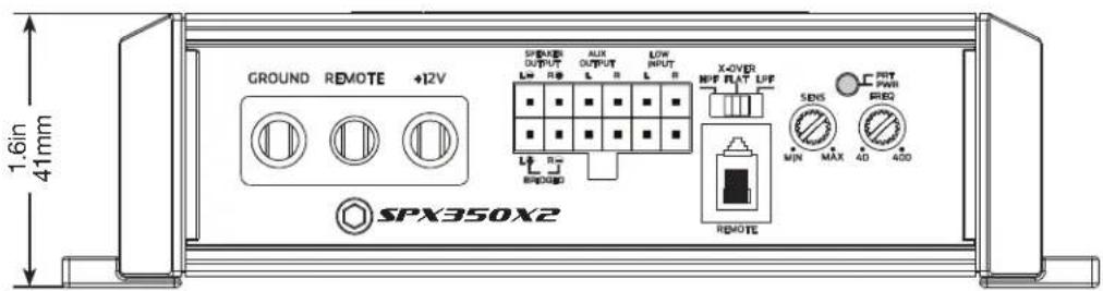
GROUND
Connect to the negative terminal of the battery or bolted to a clean, unpainted part of the chassis of the vehicle.
REMOTE
Connected to switched +12V, usually a remote trigger wire coming from the head unit or an ignition lead if one is not available.
+12V
Connect to positive terminal (+12V) of the battery. A in-line fuse should be installed within 18 inches of the battery. A 30 AMP fuse is recommended for the SPX350X2
SPEAKER OUTPUT
Used to connect the amplifier to speakers. The SPX350X2 minimum impedance is 2 ohm Stereo and 4 ohm Bridged. To Bridge the 2 channels, use Left+ and Right-
AUX OUTPUT
Provides a full range signal for an additional amplifier. There is no signal loss if using this output.
LOW INPUT
Connect preamp signal cables from head unit to these inputs. For a high-level signal, cut RCA connectors and connect to speaker wires.
REMOTE LEVEL CONTROL
This port is for connecting the remote level control knob. This allows up to 20dB of volume adjustment. Press to Mute.
X-OVER (Crossover)
HPF - FLAT - LPF is selectable. Select FLAT for full range signal. Select HPF (High Pass Filter) or LPF (Low Pass Filter) to activate the internal crossover which is continuously variable from 40Hz to 400Hz using FREQ
SENS
Used to adjust the input sensitivity (Gain) to match the input level signal. Continuously variable from 0.2V to 10V. Adjust this with the help of a DMM and a test signal or an Oscilloscope. See System Tuning section for setup instructions.
FREQ
Used to adjust the crossover frequency when crossover is set to HPF or LPF. Continuously variable from 40Hz to 400Hz
POWER/PROTECT LED
Amplifier status indicator. Blue indicates all systems working and amplifier is on. Red indicates protection mode, from Thermal Shut Down or Short Circuit (See Troubleshooting)
SPX700X4
4 Channel Power Amplifier
Connections / Settings
GROUND
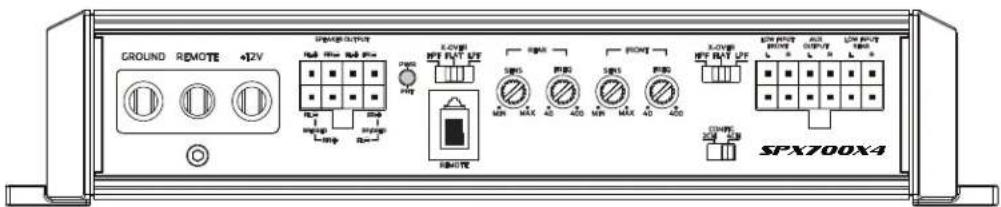
Connect to the negative terminal of the battery or bolted to a clean, unpainted part of the chassis of the vehicle.
REMOTE
Connected to switched +12V, usually a remote trigger wire coming from the head unit or an ignition lead if one is not available.
+12V
Connect to positive terminal (+12V) of the battery. A in-line fuse should be installed within 18 inches of the battery. A 60 AMP fuse is recommended for the SPX700X4
SPEAKER OUTPUT
Used to connect the amplifier to speakers. The SPX750X4 minimum impedance is 2 ohm Stereo and 4 ohm Bridged. To bridge the Rear channels, use Rear-Left(RL)- and Rear-Right+. To bridge the Front channels, use Front-Right + and Front-Left -
POWER/PROTECT LED
Amplifier status indicator. Blue indicates all systems working and amplifier is on. Red indicates protection mode, from Thermal Shut Down or Short Circuit (See Troubleshooting)
REMOTE LEVEL CONTROL
This port is for connecting the remote level control knob. This allows up to 20dB of volume adjustment. Level control is for Rear channels only.
X-OVER (REAR/FRONT)
HPF - FLAT - LPF is selectable. Select FLAT for full range signal. Select HPF (High Pass Filter) or LPF (Low Pass Filter) to activate the internal crossover which is continuously variable from 40Hz to 400Hz using FREQ
SENS
Used to adjust the input sensitivity (Gain) to match the input level signal. Continuously variable from 0.2V to 10V. Adjust this with the help of a DMM and a test signal or an Oscilloscope. See System Tuning section for setup instructions.
FREQ
Used to adjust the crossover frequency when crossover is set to HPF or LPF. Continuously variable from 40Hz to 400Hz
CONFIG
Select either 2CH inputs or 4CH inputs depending on your source unit capabilities. Select 2CH if only 2 channels of signal are available, this helps avoid having to use Y-connectors to drive 4 channels with only 2 channels of signal available.
LOW INPUTS (FRONT/REAR)
Connect preamp signal cables from head unit to these inputs. For a high-level signal, cut RCA connectors and connect to speaker wires.
AUX OUTPUT
Provides a full range signal for an additional amplifier. There is no signal loss if using this output.
Connections / Settings
SPX1000X5
5 Channel Power Amplifier

GROUND
Connect to the negative terminal of the battery or bolted to a clean, unpainted part of the chassis of the vehicle.
REMOTE
Connected to switched +12V, usually a remote trigger wire coming from the head unit or an ignition lead if one is not available.
+12V
Connect to positive terminal (+12V) of the battery. A in-line fuse should be installed within 18 inches of the battery. A 80 AMP fuse is recommended for the SPX1000X5
SPEAKER OUTPUT
SUB+/SUB- minimum impedance is 2 ohm. Channels 1-4, minimum impedance is 2 ohm Stereo and 4 ohm Bridged. To bridge the Rear channels, use Rear-Left(RL)- and Rear-Right+. To bridge the Front channels, use Front-Right + and Front-Left -
X-OVER (FRONT/ REAR)
HPF - FLAT - LPF is selectable. Select FLAT for full range signal. Select HPF (High Pass Filter) or LPF (Low Pass Filter) to activate the internal crossover which is continuously variable from 40Hz to 400Hz using FREQ
SENS
Used to adjust the input sensitivity (Gain) to match the input level signal. Continuously variable from 0.2V to 10V. Adjust this with the help of a DMM and a test signal or an Oscilloscope. See System Tuning section for setup instructions.
FREQ
Used to adjust the crossover frequency when crossover is set to HPF or LPF. Continuously variable from 40Hz to 400Hz
SUB
LPF - Low Pass Filter variable from 50Hz-250Hz Phase - Variable phase control from 0° - 180° Sonic - Sub-sonic filter variable from 10Hz-55Hz Boost - Bass frequency boost from 0-18dB
REMOTE LEVEL CONTROL
This port is for connecting the remote level control knob. This allows up to 20dB of volume adjustment. Level control is for SUB channel only.
CONFIG
Select either 2CH inputs or 5CH inputs depending on your source unit capabilities. Select 2CH if only 2 channels of signal are available, this helps avoid having to use Y-connectors to drive all channels with only 2 channels of signal available.
LOW INPUTS (FRONT/REAR/SUB)
Connect preamp signal cables from head unit to these inputs. For a high-level signal, cut RCA connectors and connect to speaker wires.
POWER/PROTECT LED
Amplifier status indicator. Blue indicates all systems working and amplifier is on. Red indicates protection mode, from Thermal Shut Down or Short Circuit (See Troubleshooting)
System tuning
- Install all system fuses.
- Set the amplifier's input sensitivity controls to their minimum positions (full counterclockwise).
- Set all amplifier signal routing switches according to your system's design.
- Make preliminary adjustments to the crossover frequency, usually 80Hz is good starting point for high and low pass. It may be necessary to fine tune the crossover frequency later for the best overall sound quality.
- If using an Remote Level Control, set it to maximum (full clockwise).
- Turn the head unit on with the volume set to minimum.
- Visually check the amplifier's has powered on by the power LED.
- Check the condition of all other components to make sure they are powered up.
- Set the headunit's tone controls, balance, and fader to the center (flat) position. Turn off any loudness or other signal processing features.
- Set the volume control of the source unit for maximum undistorted output (on most headunits / media devices this will be approximately 7/8 of maximum volume). Use a very clear and dynamic recording.


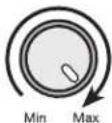


-
Turn up the input level control until the speakers reach maximum undistorted output.
-
Repeat input level adjustments for all other amplifiers.
- Reduce the source unit volume to a comfortable level.
- Listen to various musical selections to check overall system balance. Compare front to rear, midbass to midrange, etc. If one speaker set is too loud compared to another, then its level must be lowered to blend correctly with the other speakers. The idea is to reference all speakers to the weakest set.
- Fine tune crossover frequencies to achieve the smoothest possible blending of each speaker set.
- With all levels set correctly, the system will reach overall maximum undistorted output at the volume level set in step 10.
Volume Control with Mute Function
The included volume control will allow for +/- 20dB of level adjustment from the remote based on the level set in the previous step.
In some instances this will not be enough to completely mute the output level depending on the amount of input signal. In these cases, a mute function allows for instant mute of output without adjusting the volume control.
To activate the mute function, press the volume control knob inward until it clicks.
To return to previous output level; press the control knob again.
Troubleshooting
No power: Check voltage at amplifier with a DMM (volt meter), B+ and REM (with head unit on) the voltage should register between 12.2V and 14.6V when using the attached ground lead of the amplifier. Check fuse at amplifier and at the battery. Use a meter to verify connection from one end of the fuse to the other, breaks may not always be visible. If the fuse is blown, check the power wire and also the amplifier for a short. If the short is in the amplifier itself, see your Stinger dealer. If no short is present, replace the fuse.
Power without sound: Turn the amplifier off and check all input and output signal cables and power connections. Check the speakers for shorts with a DMM (volt meter) or by connecting them to another audio source. After making sure everything is correct, turn the amplifier on again.
"Motor Boating" - the power indicator going off repeatedly when the audio system is on: Check the amplifier's connection to the battery. Check battery voltage. If low, recharge or replace the battery. Check all ground connections.
Power without sound and the PROTECT LED Is Ilt: The red PROTECT LED lights when the amplifier shuts down for either thermal or over-current protection. A high internal amplifier operating temperature will trigger thermal shutdown: after it cools about 5°C, the amplifier will restart. A shorted speaker lead or operation into unusually low impedance loads will trigger over-current shutdown: cycle power at the amplifier REM terminal to restore operation. Check for shorted speaker wiring or damaged speakers or crossover systems if over-current shutdown occurs.
No sound from one side: Check the balance control in the head unit. Check speaker connections. Check signal input connection.
WARRANTY:
LIMITED WARRANTY ON AMPLIFIERS
Stinger warrants this product to be free of defects in materials and workmanship for a period of one (1) years from the original date of purchase. This warranty is not transferable and applies only to the original purchaser from an authorized Stinger dealer in the United States of America only. Should service be necessary under this warranty for any reason due to manufacturing defect or malfunction, Stinger will (at its discretion), repair or replace the defective product with new or remanufactured product at no charge. Damage caused by the following is not covered under warranty: accident, misuse, abuse, product modification or neglect, failure to follow installation instructions, unauthorized repair attempts, misrepresentations by the seller. This warranty does not cover incidental or consequential damages and does not cover the cost of removing or reinstalling the unit(s). Cosmetic damage due to accident or normal wear and tear is not covered under warranty.
INTERNATIONAL WARRANTIES:
Products purchased outside the United States of America are covered only by that country's Authorized Stinger reseller and not by Stinger. Consumers needing service or warranty information for these products must contact that country's reseller for information.
Frequent amplifier shutdown with automatic recovery: This indicates chronic amplifier thermal shutdown because of operation at consistently high internal temperatures. High operating temperature can be caused by inadequate ventilation. Make sure you are not running a lower than recommend impedance. Also check for damaged speakers or passive crossover systems. Finally, chronic thermal shutdown may result from otherwise normal operation of the amplifier at elevated output power levels, which can be resolved by providing additional amplifier cooling, installing a higher-power amplifier, or reducing amplifier output level.
Very low output: Check your head unit's fader control or the amplifier's input sensitivity level. Make sure HP frequency control is not set too high and LP frequency control is not set too low at the same time.
System Diagrams
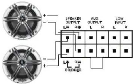
SPX350X2
TWO 4 OHM SPEAKERS
(4 OHM STEREO)
SPX350X2
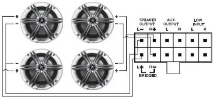
FOUR 4 OHM SPEAKERS
(2 OHM STEREO)
SPX350X2
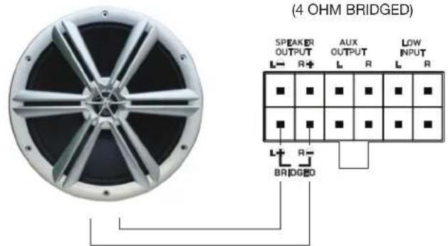
SINGLE 4 OHM SUBWOOFER
(4 OHM BRIDGED)
SPX700X4
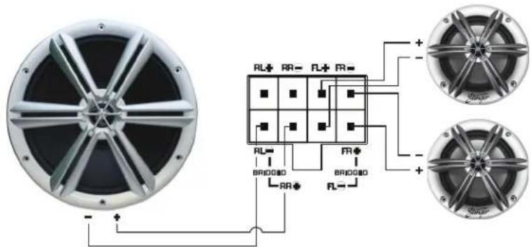
TWO 4 OHM SPEAKERS & ONE 4 OHM SUBWOOFER
(4 OHM STEREO (FRONT) & 4 OHM BRIDGED (REAR)
SPX1000X5
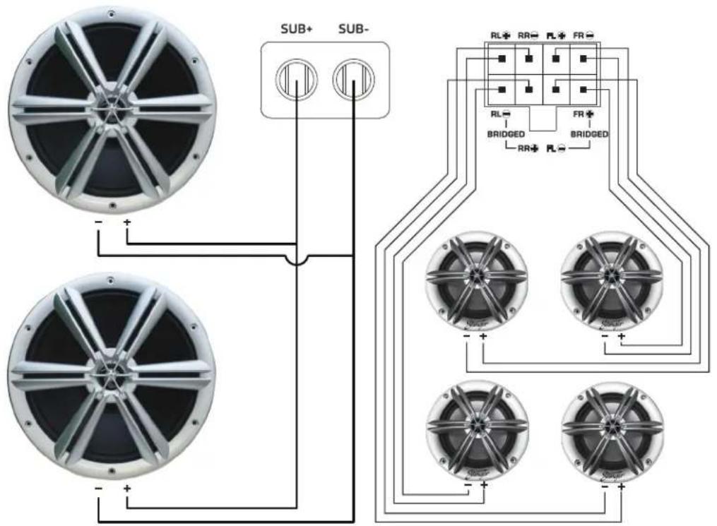
FOUR 4 OHM SPEAKERS & TWO 4 OHM SUBWOOFERS
(4 OHM STEREO (FRONT/REAR) & 2 OHM (SUB)
Stinger
Stinger is a Power Brand of AAMP Global
15500 Clearwater, Florida 33760
P: 888-228-5560
support@stingerelectronics.com
www.stingerelectronics.com
Copyright® 2019
Designed and Engineered in the USA
- Características
- Channel Power Amplifier
- Specifications
- SPX700X4
- Channel Power Amplifier
- SPX1000X5
- Channel Power Amplifier
- Connections / Settings
- SPX350X2
- GROUND
- REMOTE
- +12V
- SPEAKER OUTPUT
- AUX OUTPUT
- LOW INPUT
- REMOTE LEVEL CONTROL
- X-OVER (Crossover)
- SENS
- FREQ
- POWER/PROTECT LED
- X-OVER (REAR/FRONT)
- CONFIG
- LOW INPUTS (FRONT/REAR)
- X-OVER (FRONT/ REAR)
- SUB
- LOW INPUTS (FRONT/REAR/SUB)
- System tuning
- Volume Control with Mute Function
- Troubleshooting
- WARRANTY:
- LIMITED WARRANTY ON AMPLIFIERS
- INTERNATIONAL WARRANTIES:
- System Diagrams
- FOUR 4 OHM SPEAKERS & TWO 4 OHM SUBWOOFERS
- (4 OHM STEREO (FRONT/REAR) & 2 OHM (SUB)
- Stinger
Brand : Stinger
Model : SPX1000X5
Category : Receiver