60006 - Uncategorized WilTec - Free user manual and instructions
Find the device manual for free 60006 WilTec in PDF.


| Product Type | Utility Device (Uncategorized) |
| Brand | WilTec |
| Model | 60006 |
| Dimensions | 8.7 × 5.5 × 3.9 in (22 × 14 × 10 cm) |
| Weight | 1.3 lbs (0.6 kg) |
| Material | ABS Plastic, Metal Components |
| Power Supply | 12V DC |
| Input Voltage | 110–240V AC (50/60 Hz) |
| Output Voltage | 12V DC |
| Output Current | 2A |
| Power Consumption | 24W |
| Operating Temperature | -10°C to 40°C |
| Main Functions | ON/OFF switch, LED indicator |
| Maintenance | Clean with dry cloth, avoid moisture |
| Safety Features | Overload protection, short-circuit protection |
| Spare Parts | Replacement fuses (5x20mm, 2A) |
| General Info | Designed for indoor use only |
Frequently Asked Questions - 60006 WilTec
User questions about 60006 WilTec
0 question about this device. Answer the ones you know or ask your own.
Ask a new question about this device
Download the instructions for your Uncategorized in PDF format for free! Find your manual 60006 - WilTec and take your electronic device back in hand. On this page are published all the documents necessary for the use of your device. 60006 by WilTec.
USER MANUAL 60006 WilTec
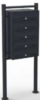
5-Door Mailbox System
60006-60008, 61744, 61754, 61760

natural_image
Exterior view of a black office building (no signage)Illustration similar, may vary depending on model
Read and follow the operating instructions and safety information before using for the first time.
Technical changes reserved!
Illustrations, functional steps, and technical data may deviate insignificantly due to continuous further developments.
Updating the documentation
If you have suggestions for improvement or have found any irregularities, please contact us.
The information contained in this document may alter at any time without prior notice. No part of this document may be copied or otherwise duplicated without prior written consent. All rights reserved. WilTec Wildanger Technik GmbH cannot be held liable for any possible mistakes in this operating manual, nor in the diagrams and illustrations shown.
Although WilTec Wildanger Technik GmbH has made every possible effort to ensure that this operating manual is complete, accurate, and up-to-date, errors cannot be ruled out entirely.
If you have found an error or wish to suggest an improvement, we look forward to hearing from you.
Send us an e-mail to:
service@wiltec.info
or use our contact form:
https://www.wiltec.de/contacts/
The most recent version of this manual in several languages can be found in our online shop:
https://www.wiltec.de/docsearch
Our postal address is:
To return your goods for exchange, repair, or other purposes, please use the following address. Attention! To allow for a trouble-free complaint or return, it is important to contact our customer service team before returning your goods.
Retourenabteilung
Thank you for choosing to purchase this quality product. To minimise the risk of injury, we ask you to always take some basic safety precautions when using this product. Please read this operating manual carefully and make sure that you understand it. Keep these operation instructions in a safe place.
Technical drawing and parts list
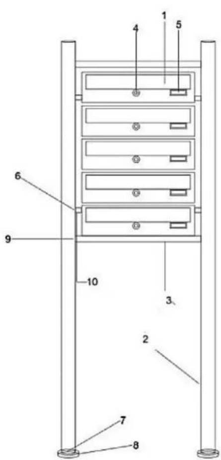
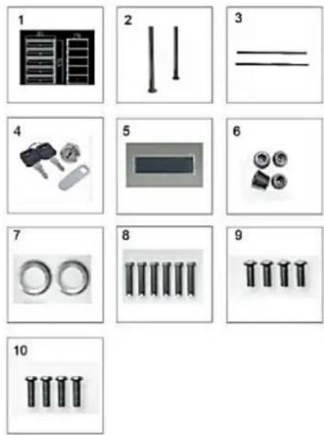
| No | Name | No | Name |
| 1 | Mailbox | 7 | Ring covers |
| 2 | Frame | 8 | Floor screws |
| 3 | Cross bars | 9 | Cross bar screws |
| 4 | Keys and locks | 10 | Spacer screws |
| 5 | Name plates | 11 | Mailbox screws |
| 6 | Spacers |
Assembly instructions
Choose a suitable location to place your mailbox system. Make sure that the surface is level and that you can anchor the frame firmly with the floor screws. We recommend that you assemble the mailbox close to where it is to be installed.
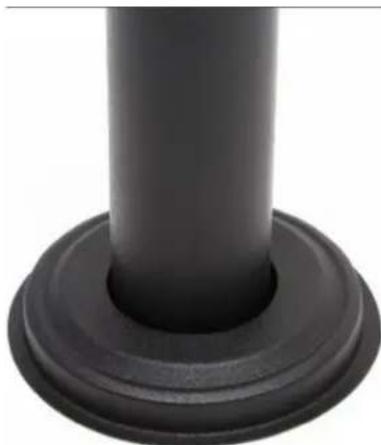
- Push the ring covers (7) onto the frame rods (2). Check that the ring is pointing in the correct direction (see fig. 1).
- Connect the frame (2) and the cross bars (3) using the screws (9). Leave the assembly loose and do not fully tighten the screws yet.
- Place the frame in the location that you have chosen and mark the mounting holes for the intended location (lift the ring covers to do this).
- Set the bracket aside and drill holes at the marked locations. Then you can attach the frame (2) with the floor screws (8). Then connect the mailbox unit (1) to each other using the screws (11).
- Now attach the mailboxes (1) with the spacers (6) between the bars of the frame (2). Use the spacer screws (10) for this.
• Now tighten all the screws and finally attach the name tags (5) to the desired locations.
natural_image
Close-up of a black cylindrical object with a circular base, resembling a floor or mechanical component (no text or symbols visible)Figure 1
Technical specifications
| 60006 | 60007 | 60008 | 61744 | 61754 | 61760 | |
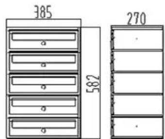
| Total dimensions (mm) | 585 × 270 × 385 | |||||
| Dimensions of foot (mm) | 1500 × 50 | 1500 × 50 | 1500 × 50 | 1500 × 50 | 1500 × 50 | 1500 × 50 |
| Number of individual boxes | 5 | |||||
Important Note:
Reproduction and any commercial use (of parts) of this operating manual, requires a written permission of WilTec Wildanger Technik GmbH.
Brand : WilTec
Model : 60006
Category : Uncategorized