
10ACC-4 - Electronic meter Daytronic - Free user manual and instructions
Find the device manual for free 10ACC-4 Daytronic in PDF.


| Product Type | 4-Channel Counter/Timer Card |
| Channels | 4 independent counter channels |
| Input Type | TTL-level (+5 V DC max), contact closure (active low) |
| Full-Scale Count Ranges | 32,767 (1 increment), 327,670 (10 increments), 3,276,700 (100 increments) |
| Debounce Time | 0.06 to 30 ms, selectable via DIP switches |
| Auxiliary Power Input | 9-15 V DC (optional, for count retention during system power-down) |
| I/O Connector | 20-pin connector, mates with Daytronic CONDITIONER CONNECTOR No. 60322 |
| Control Commands | COH, COU, COR, COC (Hold, Update, Reset, Clear) per channel |
| External Logic Control | Yes, via dedicated I/O pins for Hold, Reset, etc. |
| Default Range | 32,767 counts (until RNG command is applied) |
| Initial Mode at Power-Up | All channels in COUNT HOLD mode; COU command required for normal operation |
| Type Configuration | Factory-set as "C2" (Counter/Timer mode); TYP command not required |
| Location/Reconfiguration | LOCATE (LCT) command needed only if reconfiguring or installing card |
| Operating Environment | System power shut-down; auxiliary power keeps counts alive |
| Dimensions | Standard Daytronic card form factor (exact dimensions not specified) |
| Weight | Not specified; lightweight PCB |
| Manual Pages | 5 pages (PDF) |
Frequently Asked Questions - 10ACC-4 Daytronic
RNG x = n [CR], where x is the channel (1-4) and n is 1 (32,767 counts), 2 (327,670 counts), or 3 (3,276,700 counts). Default is 32,767 counts.INC x [CR]. This increases the count for channel x by one increment (1, 10, or 100, depending on the selected range).User questions about 10ACC-4 Daytronic
0 question about this device. Answer the ones you know or ask your own.
Ask a new question about this device
Download the instructions for your Electronic meter in PDF format for free! Find your manual 10ACC-4 - Daytronic and take your electronic device back in hand. On this page are published all the documents necessary for the use of your device. 10ACC-4 by Daytronic.
USER MANUAL 10ACC-4 Daytronic
1. 10ACC-4 CONNECTIONS
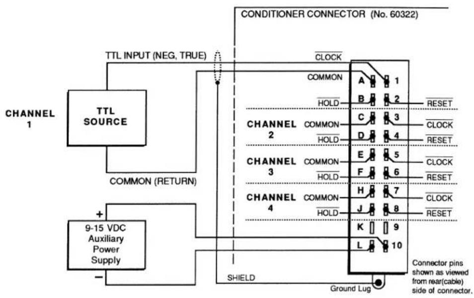
The Model 10ACC-4's 20-pin I/O CONNECTOR mates with Daytronic CONDITIONER CONNECTOR No. 60322 (shown in Fig. 1.E.1). Pin functions are given in Table 3.A.1.8, below. Cabling is given in the following figure. Each of the 10ACC-4's independent channels may be connected to either a TTL driver or contact switch.
Concerning 10ACC-4 pin connections, you should note that
a. All inputs are TTL-level (+5 V-DC maximum). Contact closures are negative true to ground (active low logic), so that a Logic 0 at Pin 1, 3, 5, or 7 causes the "clocking" of one count for Channel 1, 2, 3, or 4, respectively.
b. You may select a debounce time from 0.06 through 30 milliseconds for all four inputs (see Section d.2(b) for the procedure).
c. Like the 10ACT01, the Model 10ACC-4 provides for the application and release of "COUNT HOLD" and "COUNT RESET" by appropriate negative-true logic inputs at the I/O CONNECTOR—as well as by the entry of MNEMONIC COMMANDS (see Section d.4, below). For full details on "External Logic Specifications and Interconnections," see Appendix F of this Guidebook.
d. Unlike the 10ACT01, the Model 10ACC-4 has input provisions for a user-supplied auxiliary external power supply from 9 to 15 V-DC, which would allow you to keep each channel's count "alive" during system power shut-down (see Fig. 3.A.1.4, below).
Fig. 3.A.1.4 Model 10ACC-4 Cabling
flowchart
graph TD
    A["TTL SOURCE"] -->|COMMON (RETURN)| B["9-15 VDC Auxiliary Power Supply"]
    B --> C["SHIELD"]
    C --> D["CLOCK"]
    D --> E["CONNECTOR CONNECTOR (No. 60322)"]
    E --> F["Ground Lug"]
    F --> G["Connector pins shown as viewed from rear(cable) side of connector."]
    style A fill:#f9f,stroke:#333
    style B fill:#ccf,stroke:#333
    style C fill:#cfc,stroke:#333
    style D fill:#fcc,stroke:#333
    style E fill:#cff,stroke:#333
    style F fill:#ffc,stroke:#333
    style G fill:#fcc,stroke:#333
NOTE: Upon system powerup, ALL 10ACC-4 CHANNELS COME UP IN THE "COUNT HOLD" MODE. In order for them to perform properly, you must issue a COUNTER UPDATE (COU) command to each channel by entering a command of COU x [CR] or by applying a Logic 1 to the appropriate pin of the rear I/O CONNECTOR.
3.A.1 Counter/Timer Functions
Table 3.A.1.8
Model 10ACC-4 Pin Assignments
| I/O CONNECTOR Pin No. | 10ACC-4 Channel No. | Line Function |
| 1 | 1 | |
| A | 1 | COMMON |
| 2 | 1 | |
| B | 1 | HOLD |
| 3 | 2 | |
| C | 2 | COMMON |
| 4 | 2 | |
| D | 2 | HOLD |
| 5 | 3 | |
| E | 3 | COMMON |
| 6 | 3 | |
| F | 3 | HOLD |
| 7 | 4 | |
| H | 4 | COMMON |
| 8 | 4 | |
| J | 4 | HOLD |
| 9,K | N/C | |
| 10 | + 9-15 V-DC AUXILIARY EXTERNAL POWER INPUT | |
| L | - 9-15 V-DC AUXILIARY EXTERNAL POWER INPUT | |
N/C = Not Committed.
2. 10ACC-4 CONFIGURATION
a. SETTING RANGE AND RESOLUTION: RNG COMMAND
NOTE: Prior to shipment, each 10ACC-4 channel will have been assigned a TYPE designation of "C2" (this is the code assigned to the 10ACT01's channel in "COUNTER" ("TOTALIZER") mode, as explained in Section b.2(a), above). THEREFORE, YOU NEED NOT APPLY THE TYPE (TYP) COMMAND WHEN CONFIGURING THE 10ACC-4. Also, you will normally NOT have to "locate" the 10ACC-4's DATA CHANNELS via the LOCATE (LCT) command, unless you are "reconfiguring" them or are installing the 10ACC-4 card yourself—in which case see Appendix C.
Note too that the SENSITIVITY (SEN) command (Section b.2(c), above) does not apply to the Model 10ACC-4.
Each of the 10ACC-4's channels may be independently set for an appropriate full-scale count (with corresponding count increment) by entering, for that channel, a RANGE (RNG) command of the form
$$ \mathbf {R N G} \mathbf {x} = \mathbf {n} [ \mathbf {C R} ] ^ {*} $$
where "x" is the number of the channel being set, and "n" is "1," "2," or "3," as given in the following table:
Table 3.A.1.9.
10ACC-4 Ranges
| Full-Scale Count | Count Increment | "n" Value |
| 32767 | 1 | 1 |
| 327670 | 10 | 2 |
| 3276700 | 100 | 3 |
Until the first application of the RNG command, a "default" range of 32767 will be in effect.
b. SETTING "DEBOUNCE" TIME
You can apply the same trigger delay (from 60 microseconds to 30 milliseconds) to all four of the 10ACC-4's input lines. This provides time for the bouncing of switch contacts to subside.
To set a "debounce" time for all four inputs:
- Make sure the EEPROM Switch is OFF, and then turn OFF DataPAC power.
- Remove the 10ACC-4 Card from its SLOT (see Appendix B for "Card Insertion and Removal").
- Locate the DIP-switch block on the 10ACC-4 board. The switches are shown in Fig. 3.A.1.5, below.
Fig. 3.A.1.5. Model 10ACC-4 Debounce Switches

- Referring to the following table, position the switches for the desired debounce time.
Table 3.A.1.10
Model 10ACC-4 Debounce Settings
| Debounce Time (milliseconds) | Switch Settings |
| 0.06 | All Switches OFF ("OPEN") |
| 1.5 | Only Switch No. 1 ON ("CLOSED") |
| 3.0 | Only Switch No. 2 ON |
| 4.5 | Only Switch Nos. 1 and 2 ON |
| 6.0 | Only Switch No. 3 ON |
| 7.5 | Only Switch Nos. 1 and 3 ON |
| 9.0 | Only Switch Nos. 2 and 3 ON |
| 10.5 | Only Switch Nos. 1, 2, and 3 ON |
| 15.0 | Only Switch No. 4 ON |
| 16.5 | Only Switch Nos. 1 and 4 ON |
| 18.0 | Only Switch Nos. 2 and 4 ON |
| 19.5 | Only Switch Nos. 1, 2, and 4 ON |
| 21.0 | Only Switch Nos. 3 and 4 ON |
| 22.5 | Only Switch Nos. 1, 3, and 4 ON |
| 28.5 | Only Switch Nos. 2, 3, and 4 ON |
| 30.0 | All Switches ON |
3. INCREMENTING THE COUNT: INC COMMAND
An INCREMENT (INC) command of the form
$$ \mathrm{INC} \times [ \mathrm{CR} ] $$
may be applied to any one of the 10ACC-4's channels (No. x) to increase its count reading by one increment (1, 10, or 100, depending on the full-scale count selected for that channel via the RANGE (RNG) command, above).
4. COUNTER CONTROL: COH, COU, COR, AND COC COMMANDS
These four commands are discussed in Section c.2, above, with reference to the Model 10ACT01 Counter/Timer Card in "COUNTER" or "TIMER" mode. Each command may also be used with the Model 10ACC-4, but is here applied individually to only one of the card's four counter channels.
NOTE THAT EACH COMMAND AFFECTS ONLY THE SCANNED DATA READING OF THE CHANNEL TO WHICH IT IS APPLIED (IN MOST CASES, THIS WILL BE A DISPLAYED VALUE). EACH 10ACC-4 CHANNEL WILL ALWAYS CONTINUE TO ACCUMULATE COUNTS, REGARDLESS OF THE "CONTROL" COMMAND PRESENTLY IN EFFECT FOR THAT CHANNEL, AND OF THE DISPLAYED READING THAT RESULTS FROM THE APPLICATION OF THAT COMMAND.
As with the Model 10ACT01, the effects of the four "COUNT CONTROL" commands can also be obtained by the application of appropriate logic inputs to the 10ACC-4's rear I/O CONNECTOR. Thus,
a. TO HOLD THE COUNT VALUE for a 10ACC-4's Channel No. x, you may apply a command of
$$ \mathrm{COH} \times [ \mathrm{CR} ] $$
Alternatively, a Logic 0 at Pin B, D, F, or J of the 10ACC-4's rear I/O CONNECTOR will "hold" the existing scanned data reading for the corresponding channel, and may be "ORed" with a COUNTER HOLD (COH) command.
b. TO UPDATE THE COUNT VALUE for a 10ACC-4's Channel No. x, you may apply a command of
COU x [CR]
Alternatively, a Logic 1 at Pin B, D, F, or J of the 10ACC-4's rear I/O CONNECTOR will release an existing "hold" condition for the corresponding channel, instantly updating that channel's display and resuming its normal counting operation. Such an input may be "ORed" with a COUNTER UPDATE (COU) command.
C. TO RESET THE COUNT for a 10ACC-4's "unheld" Channel No. x, you may apply a command of
COR x [CR]
Alternatively, a Logic 0 at Pin 2, 4, 6, or 8 of the 10ACC-4's rear I/O CONNECTOR will set and hold at zero the scanned data reading for the corresponding channel, if no COUNTER HOLD (COH) is in effect for the channel, and if the channel's "HOLD" pin is at Logic 1. Such an input may be "ORed" with a COUNTER RESET (COR) command.
d. TO CLEAR THE COUNT for a 10ACC-4's "unheld" Channel No. x, you may apply a command of
COC x [CR]
Alternatively, a Logic 1 at Pin 2, 4, 6, or 8 of the 10ACC-4's rear I/O CONNECTOR will release an existing "reset" condition for the corresponding channel, causing it to resume normal updating (from zero), if no COUNTER HOLD (COH) is in effect for the channel, and if the channel's "HOLD" pin is at Logic 1. Such an input may be "ORed" with a COUNTER CLEAR (COC) command.
Brand : Daytronic
Model : 10ACC-4
Category : Electronic meter