
VisionPoint 55 - Security Camera 3VR - Free user manual and instructions
Find the device manual for free VisionPoint 55 3VR in PDF.


| Product Type | IP Security Camera |
| Model | VisionPoint 55 |
| Brand | 3VR |
| Resolution | Up to 2 MP (1920 x 1080) |
| Lens | Fixed or varifocal (2.8-12mm) |
| Field of View | 90° to 30° (depending on lens) |
| Night Vision | IR LEDs up to 30m |
| Power Supply | PoE (802.3af) or 12V DC |
| Power Consumption | < 8W |
| Dimensions (W x H x D) | 70 x 70 x 160 mm |
| Weight | 500 g |
| Housing | Indoor/Outdoor, IK10 rated |
| Operating Temperature | -20°C to 50°C |
| Storage | microSD card slot (up to 128GB) |
| Network | 10/100 Ethernet, Wi-Fi optional |
| Compatible Software | 3VR OpCenter, Spot Monitor, Evidence Viewer |
| Analytics | Motion detection, facial recognition, line crossing |
| Two-Way Audio | Built-in microphone and speaker |
| Maintenance | Clean lens with soft cloth; reboot periodically |
| Security | Password protection, HTTPS, user permissions |
| Warranty | 2 years |
Frequently Asked Questions - VisionPoint 55 3VR
User questions about VisionPoint 55 3VR
0 question about this device. Answer the ones you know or ask your own.
Ask a new question about this device
Download the instructions for your Security Camera in PDF format for free! Find your manual VisionPoint 55 - 3VR and take your electronic device back in hand. On this page are published all the documents necessary for the use of your device. VisionPoint 55 by 3VR.
USER MANUAL VisionPoint 55 3VR
natural_image
Interior view of a modern multi-level shopping mall with escalators and staircases, featuring a close-up inset of a person walking on an escalator (no visible text or signage)3VR VIDEO INTELLIGENCE PLATFORM™
3VR USER MANUAL 7.0
A comprehensive reference for
- VIP OpCenter
• VIP Report Viewer
• VIP Spot Monitor
• VIP Evidence Viewer
3VR VIDEO INTELLIGENCE PLATFORM™
3VR USER MANUAL 7.0
3VROC-UM7.0-R3
CHAPTER 1: OPCENTER BASICS
- INSTALLING OPCENTER 16
1.1 System Requirements 16
1.2 Running the 3VR Client Application Installation Wizard 16
- SIGNING IN 18
2.1 Signing in to OpCenter 18
2.2 Enterprise OpCenter | Selecting an Appliance 19
2.3 Managing the Appliance List 19
- OPCENTER OVERVIEW 21
3.1 OpCenter Panel Layout 21
3.2 Resizing and Closing OpCenter 22
3.3 Enterprise OpCenter | Switching Between Appliances After Sign In 22
- OPCENTER ADMINISTRATION 23
4.1 Changing Your 3VR Password 23
4.2 Setting the Company Name 23
4.3 Resetting OpCenter to Default Settings 24
4.4 Viewing and Copying Appliance Information 24
CHAPTER 2: VIDEO PANEL
-
GETTING STARTED WITH THE VIDEO PANEL 28
-
CUSTOMIZING THE VIDEO PANEL 29
2.1 Changing the Number and Size of Video Players 29
2.2 Adding and Removing Cameras 29
2.3 Camera Views 31
2.4 Camera Overlays 32
2.5 Showing or Hiding the Video Timeline and Camera Tree 32
2.6 Switching to Full Screen Mode 33
- VIEWING LIVE AND STORED VIDEO 35
3.1 Live Video 35
3.2 Stored Video 35
3.3 Video Playback Controls 36
- PTZ CAMERA CONTROLS 37
4.1 Overview 37
4.2 Compass Mode 37
4.3 Click to Center Mode 38
4.4 Joystick Mode 38
4.5 Preset Views 39
4.6 Tours 40
4.7 PTZ Camera Focus and Iris Control 41
- DIGITAL ZOOM 42
5.1 Entering Zoom Mode 42
5.2 Shifting the Zoomed Region 43
5.3 Exiting Zoom Mode 43
-
OPENING A SECOND VIDEO PANEL 44
-
PANORAMIC STITCHING 45
7.1 Creating a New Stitched View 45
7.2 Loading a Saved Stitched View 46
- EXPORTING VIDEO AND IMAGES FROM THE VIDEO PANEL 47
8.1 Exporting Video 47
8.2 Saving a Single Frame as an Image 49
CHAPTER 3: MONITOR PANEL
-
GETTING STARTED WITH THE MONITOR PANEL 52
-
VIEWING EVENTS 53
2.1 Event Card Types 53
2.2 Event Video 54
2.3 Event Details 55
- CUSTOMIZING THE MONITOR PANEL 56
3.1 Changing the Time Interval 56
3.2 Changing the Appearance of Event Cards and Event Images 57
3.3 Showing or Hiding the Event Editor and Video Player 58
- USING THE CAMERA SELECTOR 58
4.1 Viewing Camera Names 58
4.2 Selecting Cameras Individually 59
4.3 Selecting Multiple Cameras and Camera Groups 59
4.4 Creating a Camera Group 60
4.5 Editing or Deleting a Camera Group 60
-
VIEWING EVENT VIDEO IN THE POP-UP VIDEO PLAYER 61
-
VIEWING LIVE VIDEO IN THE MONITOR PANEL 61
-
EXPORTING IMAGES 62
7.1 Image Quick Save 62
7.2 Saving Images to an Event Card 62
7.3 Enhancing Images 62
7.4 Exporting Images 63
7.5 Printing Images 63
7.6 Emailing Images 64
- EXPORTING EVENTS 65
8.1 Printing Events 65
8.2 Emailing Events 65
8.3 Exporting Events 67
CHAPTER 4: SEARCH PANEL
-
GETTING STARTED WITH THE SEARCH PANEL 70
-
BUILDING A SEARCH 71
2.1 Specify Date and Time Range 71
2.2 Select Cameras 71
2.3 Enterprise OpCenter | Select Appliances 72
2.4 Select Event Types 72
2.5 Reviewing Search Criteria and Running the Search 74
-
VIEWING SEARCH RESULTS 74
-
ADVANCED SEARCH OPTIONS 75
4.1 Searching for Correlated Events 75
4.2 Searching for Motion in a Region 76
4.3 Searching for Specific Faces 76
- SAVING SEARCHES 78
5.1 Storing Search Criteria as a Saved Search 78
5.2 Running a Saved Search 79
5.3 Modifying or Deleting a Saved Search 79
6. SEARCHING FROM AN EVENT OR PERSON CARD 80
6.1 Search for Camera 80
6.2 Search for Time 80
6.3 Search for Person 80
- EXPORTING SEARCH RESULTS 81
CHAPTER 5: ALERTS PANEL
1. GETTING STARTED WITH THE ALERTS PANEL 84
- CREATING AN ALERT 85
2.1 Set Alert Name and Color 85
2.2 Select Days and Times 85
2.3 Select Cameras 85
2.4 Select Event Types 86
2.5 Specify Alert Action 86
2.6 Outline Alert Response Procedure 86
2.7 Save and Enable the New Alert : 87
- ALERT ACTIONS 88
3.1 Viewing Alert Actions 88
3.2 Configuring a New Email Alert Action 88
3.3 Creating a New Settings Change Alert Action 90
- VIEWING ALERT EVENTS 91
CHAPTER 6: CASES PANEL
1. GETTING STARTED WITH THE CASES PANEL 94
1.1 Cases Panel Overview 94
1.2 Cases Panel Layout 94
- WORKING WITH CASES 95
2.1 Viewing an Existing Case 95
2.2 Opening a New Case 95
2.3 Editing a Case 97
2.4 Deleting a Case 97
- BUILDING A CASE 97
3.1 Adding Events to a Case 97
3.2 Adding a Person to a Case 98
3.3 Removing Evidence from a Case 98 - ADDING SUPPORTING DOCUMENTS AND NOTES TO A CASE 99
4.1 Adding a Document to a Case 99
4.2 Working with Documents 100
4.3 Adding Notes to a Case 101 - EXPORTING A CASE 101
CHAPTER 7: PEOPLE PANEL
- GETTING STARTED WITH THE PEOPLE PANEL 104
- WORKING WITH FACE EVENTS 105
2.1 Creating a New Person from a Face Event 105
2.2 Matching a Face Event to an Existing Person 105 - FILTERING AND SORTING PERSON CARDS 106
3.1 Filtering People by Group Membership 106
3.2 Sorting People Chronologically 107
3.3 Filtering People by Name, ID, Gender, and Other Custom Properties 107 - PEOPLE GROUPS 108
4.1 Creating a New Group 108
4.2 Editing People Groups 109
4.3 Deleting People Groups 109 - VIEWING AND EDITING PERSON DETAILS 110
- WORKING WITH PERSON PROFILES 110
6.1 Viewing Profiles Matched to a Person Card 110
6.2 Changing the Display Profile 111
6.3 Unmatching a Profile from a Person Card 111
6.4 Person Profile Images 112 - MERGING TWO PERSON CARDS 113
- EXPORTING PEOPLE 114
8.1 Exporting People 114
8.2 Enterprise OpCenter | Exporting People to Another Appliance 115
CHAPTER 8: NOTES
- ABOUT NOTES 118
1.1 Notes Overview 118
1.2 Viewing a Note 118
- ADDING A NOTE 119
2.1 Adding a Note 119
2.4 Re-Labeling a Note 120
- MANAGING NOTE LABELS 121
3.1 Creating a Custom Note Label 121
3.2 Editing or Deleting a Note Label 121
CHAPTER 9: VIEWING EXPORTED EVIDENCE
-
VIEWING EXPORTED EVENTS, PEOPLE, AND CASES 124
-
VIEWING EXPORTED VIDEO 125
2.1 Viewing Exported Video in Evidence Viewer 125
2.2 Viewing Exported Video in a Supported Media Player 125
- EVIDENCE VIEWER OVERVIEW 126
3.1 About Evidence Viewer 126
3.2 Obtaining Evidence Viewer 126
- OPENING EXPORTED VIDEO IN EVIDENCE VIEWER 126
4.1 Automatically Load Video from Export Folder 126
4.2 Manually Select Export Folder 127
- REVIEWING VIDEO IN EVIDENCE VIEWER 128
5.1 Controlling Video Playback 128
5.2 Saving a Single Frame as an Image 129
- CUSTOMIZING EVIDENCE VIEWER 129
6.1 Changing the Number and Size of Video Players 129
6.2 Adding and Removing Cameras 130
6.3 Camera Overlays 131
6.4 Showing or Hiding the Video Timeline and Camera Tree 131
- DIGITAL ZOOM 132
7.1 Entering Zoom Mode 132
7.2 Shifting the Zoomed Region 133
7.3 Exiting Zoom Mode 133
8. VALIDATING EXPORTED EVIDENCE 133
8.1 About Evidence Validation 133
8.2 Validating Exported Events, People, and Cases in 3VR OpCenter 133
8.3 Validating Exported Video in 3VR Evidence Viewer 135
CHAPTER 10: IMPORTING
- IMPORTING OVERVIEW 138
- CONFIGURE IMPORT CAMERA ON APPLIANCE 138
- IMPORTING EVENTS 140
3.1 Importing Events from XML 140
3.2 Importing Events from Video 141
3.3 Viewing Imported Events 141 - IMPORTING CASES 143
4.1 Importing Cases from XML 143
4.2 Viewing Imported Cases 143 - IMPORTING PEOPLE 144
5.1 Importing People from XML 144
5.2 Importing People from Images 145
5.3 Importing People from 3VR CrimeDex 149
5.4 Viewing Imported People 150
CHAPTER 11: REPORT VIEWER
- INSTALLING REPORT VIEWER 154
1.1 System Requirements 154
1.2 Running the 3VR Client Application Installation Wizard 154
2. SIGNING IN 156
3. REPORT VIEWER OVERVIEW 157
3.1 About Report Viewer 157
3.2 Report Viewer Layout 157
3.3 Resizing and Closing Report Viewer 157
3.4 Enterprise Report Viewer | Switching Between Appliances After Sign In 158
- CREATING A NEW REPORT DEFINITION 159
4.1 Select Cameras 159
4.2 Select Event Types 159
4.3 Enterprise Report Viewer | Select Appliances 160
4.4 Edit Report Parameters 160
4.5 Edit Report Data 161
4.6 Create Reporting Schedule 162
4.7 Save Report Definition 162
- MODIFYING AN EXISTING REPORT DEFINITION 163
5.1 Editing a Report Definition 163
5.2 Deleting a Report Definition 163
- RUNNING REPORTS 164
6.1 Generating a Report 164
6.2 Viewing a Saved Report 165
6.3 Exporting and Printing Reports 166
6.4 Deleting Saved Reports 167
CHAPTER 12: SPOT MONITOR
- INSTALLING SPOT MONITOR 170
1.1 System Requirements 170
1.2 Running the 3VR Client Application Installation Wizard 170
-
SIGNING IN 172
-
SPOT MONITOR OVERVIEW 173
3.1 About Spot Monitor 173
3.2 Resizing and Closing Spot Monitor 173
- CONFIGURING SPOT MONITOR 174
4.1 Sequential View 174
4.2 Multiplex View 175
- WATCHING SPOT MONITOR 177
3VR Inc. (hereinafter "3VR") provides this manual "AS IS," for informational use only, without warranty of any kind, expressed or implied, including but not limited to representations or warranties with respect to the contents hereof and specifically disclaims any implied warranties of merchantability or fitness for any particular purpose. 3VR reserves the right to revise this manual and to make changes in its content without obligation to notify any person or organization of such revision or change. In no event shall 3VR, Inc., its Directors, Officers, or Employees be liable for any indirect, special, incidental, or consequential damages (including damages for loss of profits, loss of business, loss of use or data, interruption of business and the like), even if 3VR has been advised of the possibility of such damages arising from any defect or error in this manual or product.
3VR Inc., 3VR, and the 3VR logo are trademarks of 3VR. 3VR may have patents, patent applications, trademarks, copyrights, or other intellectual property rights covering subject matter in this document. Except as expressly provided in any written license from 3VR, the furnishing of this document does not give you any license to these patents, patent applications, trademarks, copyrights, or other intellectual property. Other products, trademarks or names appearing in this document may or may not be trademarks, licensees, or copyrights of their respective owners and are used only for identification or explanation and to the owners' benefit, without intent to infringe.
The persons depicted in this document are, to the best of 3VR's knowledge, employees of 3VR or casual passers-by, and are neither suspected of any crime nor have they been convicted of any crime. The incidents portrayed and the names used in this document are fictitious and any resemblance to the names, character, or history of any actual person, living or deceased, is coincidental and unintentional.
3VR User Manual 7.0 © 2004 - 2011 3VR, Inc.
Release 7.0
Last modified November 28, 2011
3VROC-UM7.0-R3
CHAPTER 1
OpCenter Basics
1. INSTALLING OPCENTER 38
1.1 System Requirements 38
1.2 Running the 3VR Client Application Installation Wizard 38
2. SIGNING IN 40
2.1 Signing in to OpCenter 40
2.2 Enterprise OpCenter | Selecting an Appliance 41
2.3 Managing the Appliance List 41
3. OPCENTER OVERVIEW 43
3.1 OpCenter Panel Layout 43
3.2 Resizing and Closing OpCenter 44
3.3 Enterprise OpCenter | Switching Between Appliances After Sign In 44
4. OPCENTER ADMINISTRATION 45
4.1 Changing Your 3VR Password 45
4.2 Setting the Company Name 45
4.3 Resetting OpCenter to Default Settings 46
4.4 Viewing and Copying Appliance Information 46
1. INSTALLING OPCENTER
1.1 System Requirements
3VR OpCenter™ client software allows you to access a 3VR VIP Appliance from any PC on your network that meets the minimum system requirements.
3VR Client Applications Minimum System Requirements — Single Display
| Operating System Windows | XP Professional SP2 or later, Windows Vista, Windows 7 |
| Processor Intel and AMD CPUs, 1.1 GHz or higherNote: Video playback performance will be dictated by CPU capabilities. | |
| Display Any display capable of 1024x768 resolution or greater | |
| Video Card DirectX 9-capable video graphics adapter | |
| Memory 1 GB RAM or greater | |
| Storage 1 GB available storage space | |
| Bandwidth Broadband connection (384 Kbps or greater) to 3VR applianceremcommended. Greater bandwidth will result in a better user experiencewhen viewing stored or live video. | |
3VR OpCenter™ 7.0 features support for multiple displays. Users intending to stream video on more than one monitor must also meet the additional requirements for multi-screen display:
Additional Requirements for Multi-Screen Display
| Processor Intel and AMD CPUs, 3.0 GHz or higher |
| Video Card DirectX 9-capable video graphics adapter with support for multiple displays |
| Memory 2 GB RAM or greater |
1.2 Running the 3VR Client Application Installation Wizard
Follow these steps to install one or more of the 3VR Client Applications on a PC.
-
Double-click Installer-Client-Applications-7.0.1.XXXXX.exe to begin the installation process.
-
The 3VR Client Applications require the Microsoft .NET Framework 4.0 to function.
If Microsoft .NET Framework 4.0 is not present on your PC, the InstallShield Wizard will install it as the first step in the installation process.
Click Install to proceed.

Note
It may take up to 5 minutes to install Microsoft .NET Framework 4.0.
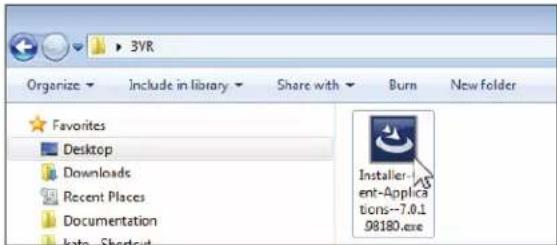

-
At the InstallShield Wizard Welcome screen, click Next.
-
The InstallShield Wizard will display the 3VR Client Applications End User License Agreement.
Read the agreement, then click ( )I accept the terms in the license agreement.
-
Click Next.
-
Specify the installation type:
• To install OpCenter, click ()Typical then click Next.
- Click Install to begin the installation.
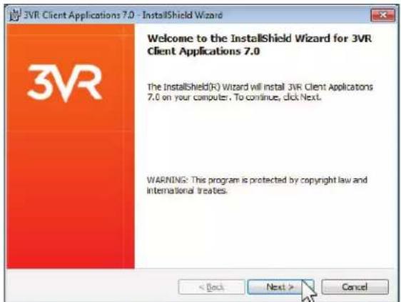


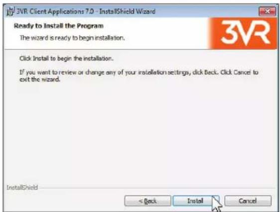
- When installation is complete, click Finish to exit the wizard.

2. SIGNING IN
2.1 Signing in to OpCenter
Follow these steps to sign in to OpCenter.
- Double-click the 3VR OpCenter desktop icon to launch the application. Alternatively, click the Windows Start menu > All Programs > 3VR Client Applications 7.0 > 3VR OpCenter.
- At the sign in screen, type the User Name and Password of your 3VR user account.
- Specify the appliance to connect to:
- If this is your first time signing in to OpCenter on this PC, type the IP address of the 3VR system in the Appliance box. This is the address provided to you by the 3VR administrator, in the format XXX.XXX.XXX.XXX (four 1-3 digit numbers separated by periods). For example, 10.100.2.22.
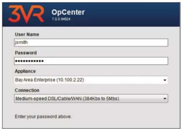
- If you have signed into OpCenter previously on this PC, open the Appliance drop-down menu and select the system to connect to.

Trouble Signing In?
If you do not know the user name or password of your 3VR user account, please contact the 3VR administrator at your organization or your 3VR reseller. If you do not know the IP address of your 3VR appliance, it may be possible to find it on the local network using the Find Local Appliance tool — see section 2.3 of this chapter for more information.
- Specify your connection type:
• If you will connect to the 3VR appliance over a Local Area Network (LAN), select High-speed LAN/WAN.
- If you will connect to the 3VR appliance over a connection with speeds between 384 Kbps and 5 Mbps, select Medium-speed DSL/Cable/WAN.
- If you will connect to the 3VR appliance using a low-speed connection below 384 Kbps, select Low-speed Dialup/DSL/Cable/WAN.
- Click Sign In.
2.2 Enterprise OpCenter | Selecting an Appliance
Customers with multiple 3VR VIP Appliances connected to an Enterprise Appliance will be prompted to select a system to connect to upon signing in to OpCenter.
- Browse through the appliance tree to locate the appliance of interest, or type the first few characters of the appliance name to filter.
- Select the appliance to connect to.
- Click Connect.

2.3 Managing the Appliance List
When signing in to a 3VR Client Application for the first time, you must type the IP address of a system to connect in the Appliance box. After you have successfully connected to the appliance, its IP address and hostname will be remembered by the application for future reference. You may view the list of appliances and manually add or remove addresses from the Edit Connect List dialog, accessed with the following steps:
- At the sign in screen, click the drop-down arrow next to Appliance.
- Select Edit Connect List.
Viewing the Appliance List
- Click ( )Show all appliances to display all appliances that you have connected to in the past.
- Click ( )Show only enterprise appliances to display only Enterprise Appliances.


Manually Adding an Appliance to the List
-
Click Add to add a new appliance to the list.
-
Type the IP address of the 3VR system in the Host Name or IP Address box.

Note
The system's display name will be retrieved after you connect to the appliance for the first time.
- Click Save.
- Repeat steps 1-3 to add additional appliances.
- When you are finished adding appliances, select the appliance to connect to from the list, then click Close to return to the sign in screen.
Editing or Removing a Saved Appliance
To edit the IP address of an appliance or remove it from the connect list:
-
Select the appliance to be modified.
-
To change the IP address associated with the appliance, click Edit. Type a new IP address, then click Save.
• To remove it from the list, click Remove. -
When you are finished, click Close to return to the sign in screen.


Finding Appliances on the Local Network
Use the following steps to find and connect to 3VR appliances on the local network:
-
Click Find Local Appliance.
-
If any appliances are found, their IP addresses will populate in the lower box.
Click an appliance from the list to select it, then click Connect.

3. OPCENTER OVERVIEW
3.1 OpCenter Panel Layout

Video Panel
Use the Video panel to watch live and stored video. You can view one camera at a time or watch multiple cameras simultaneously. The Views feature allows you to save frequent camera arrangements for quick reference.
Monitor Panel
The Monitor panel presents a real-time view of events as they are generated on the system. View all events, or filter the results by camera, event type, or time.
Search Panel
The Search panel enables you to quickly locate events of interest. In addition to standard criteria like date, time, and camera number, you can refine the search based on plug-in properties, such as transaction data (account number, withdrawal amount, etc.). Frequent searches may be stored in the Search panel for later use.
Alerts Panel
Using the Alerts panel, you can instruct the VIP Appliance to perform a specified action when video that matches certain criteria is recorded on the system. For example, you can set up an alert that will email a manager and increase video recording quality whenever motion is detected in a restricted area after hours.
Cases Panel
If there is an incident recorded on multiple cameras or involving multiple people, create a case in the Cases panel to centrally manage evidence as you build your investigation.
People Panel
The People panel allows you to view profiles of known people captured in face events.

Note
Face events will not appear unless VIP Facial Surveillance has been purchased for the appliance and configured on one or more cameras. Contact your 3VR Sales representative or 3VR reseller for more information about face and other analytics.
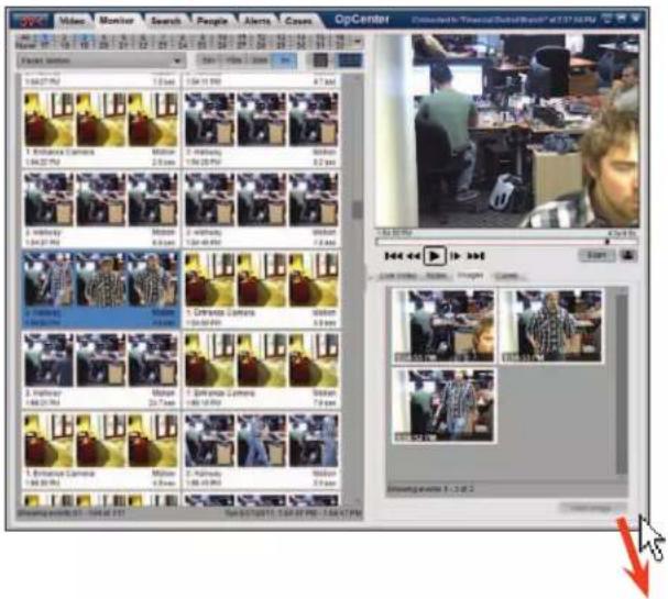
3.2 Resizing and Closing OpCenter
3VR OpCenter can be minimized and maximized in the same way as any other Windows application using the controls in the upper-right corner.
To close OpCenter, click the X button.
To customize the size of the OpCenter window, click and drag any edge of the window until it has reached the desired size.
Click and drag a corner of the window to resize the window vertically and horizontally at the same time.

3.3 Enterprise OpCenter | Switching Between Appliances After Sign In
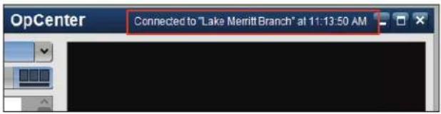
Immediately after signing in to Enterprise OpCenter, the user selects the initial VIP Appliance to connect to from the appliance selector. Thereafter, the active appliance is displayed in the status bar in the top-right corner of OpCenter.
To switch to a different appliance on the Enterprise:
-
Click the 3VR button in the top-left corner of the application and select Connect to Appliance from the menu.
-
When the appliance selector loads, select a new appliance from the list, then click Connect.

4. OPCENTER ADMINISTRATION
4.1 Changing Your 3VR Password
You can change the password you use to sign in to OpCenter and other 3VR Client Applications with the following steps:
- Click the 3VR button in the top-left corner of the application and select Change Password from the menu.

- In the Change Password dialog box, type a new password in the New password and Retype new password boxes.
- Click OK to change your password.
4.2 Setting the Company Name
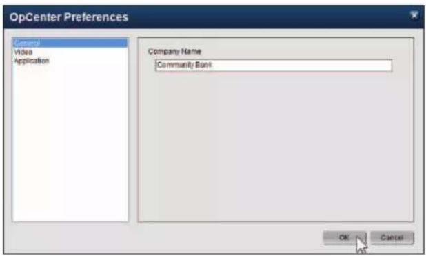
Use these steps to enter your company name in OpCenter's settings. Entering a company name will help 3VR identify your PC and appliance when providing technical support.
- Click the 3VR button in the top-left corner of the application and select Edit Preferences from the menu.

-
The OpCenter Preferences dialog will open to the General page. Type the name of your company in the Company Name box.
-
Click OK.

4.3 Resetting OpCenter to Default Settings
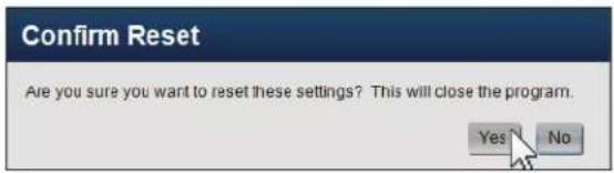
OpCenter can be reset to its default settings from the OpCenter Preferences dialog:
- Click the 3VR button in the top-left corner of the application and select Edit Preferences from the menu.

- In the OpCenter Preferences dialog, click the Application page. Select which settings to reset:
- Clears the OpCenter Sign In screen, including the list of previously accessed appliances.
b. [ ]Reset Preferences
- Resets all settings in the Preferences dialog to their defaults.
-
Clears currently selected options in the Video and Monitor panels.
-
Click OK.
-
In the pop-up dialog that appears, click Yes to continue.
OpCenter will close.

4.4 Viewing and Copying Appliance Information
In the course of troubleshooting, 3VR Technical Support, your reseller, or your internal IT staff may request information about the appliance you are connected to in OpCenter. Appliance information can be viewed and copied to the Windows clipboard with the following steps:
- Click the 3VR button in the top-left corner of the application and select Display Appliance Information from the menu.

- The Appliance Information dialog will open with information about the active appliance, the Enterprise appliance (if applicable),
and your client applications.
Click Copy To Clipboard to copy the information to the Windows clipboard.
- Click OK to close the Appliance Information dialog.
- Hold the Ctrl key on your keyboard and press V to paste the copied text into another an application, such as Microsoft Outlook.

CHAPTER 2
Video Panel
-
GETTING STARTED WITH THE VIDEO PANEL 28
-
CUSTOMIZING THE VIDEO PANEL 29
2.1 Changing the Number and Size of Video Players 29
2.2 Adding and Removing Cameras 29
2.3 Camera Views 31
2.4 Camera Overlays 32
2.5 Showing or Hiding the Video Timeline and Camera Tree 32
2.6 Switching to Full Screen Mode 33
- VIEWING LIVE AND STORED VIDEO 35
3.1 Live Video 35
3.2 Stored Video 35
3.3 Video Playback Controls 36
- PTZ CAMERA CONTROLS 37
4.1 Overview 37
4.2 Compass Mode 37
4.3 Click to Center Mode 38
4.4 Joystick Mode 38
4.5 Preset Views 39
4.6 Tours 40
4.7 PTZ Camera Focus and Iris Control 41
- DIGITAL ZOOM 42
5.1 Entering Zoom Mode 42
5.2 Shifting the Zoomed Region 43
5.3 Exiting Zoom Mode 43
-
OPENING A SECOND VIDEO PANEL 44
-
PANORAMIC STITCHING 45
7.1 Creating a New Stitched View 45
7.2 Loading a Saved Stitched View 46
- EXPORTING VIDEO AND IMAGES FROM THE VIDEO PANEL 47
8.1 Exporting Video 47
8.2 Saving a Single Frame as an Image 49
1. GETTING STARTED WITH THE VIDEO PANEL
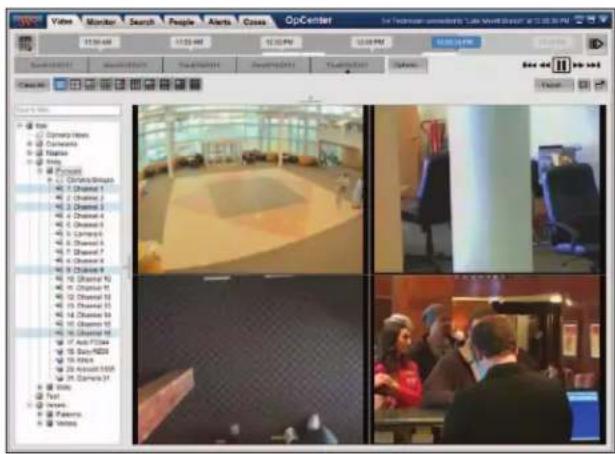
The first time OpCenter is launched on a PC, the application will load to the Video panel. The panel will contain a single blank video player, as no cameras have been selected.
On the left-hand side of the Video panel you will see the camera tree with the name of the VIP Appliance or VIP Enterprise at the top.

-
Click the plus sign next to the name of the appliance or Enterprise to expand the camera tree.
-
When connected to a single VIP appliance, the camera tree will display the list of cameras on the system.
-
When connected to a VIP Enterprise, the camera tree will show cameras from all systems on the Enterprise, organized first by region and then by appliance.
-
Click and drag a camera from the camera tree to the player to begin watching video in the video player.

Live video from the camera will stream in the player.

2. CUSTOMIZING THE VIDEO PANEL
2.1 Changing the Number and Size of Video Players
The layout selector at the top of the Video panel controls the number and arrangement of video players.
- Click a different layout button to increase or decrease the number and positioning of players as desired.

Up to 36 cameras can be displayed at a time in the Video panel.

More
To view more than 36 cameras simultaneously, use the Multi-Screen Video Player. See section 6 of this chapter for details.
- When you have decided on a player layout, click and drag a camera to each blank video player as described in section 1.

Tip
To rearrange the selected cameras, click and drag the mouse from one video player to another video player. When you release the mouse button, the cameras will switch places.

2.2 Adding and Removing Cameras
Which cameras are displayed in the Video player can be specified in a number of ways.
Adding Cameras With Drag and Drop
You can drag and drop the following items from the camera tree to the video players:
• A single camera
- A camera group (will load all cameras in the camera group)

Note
See Chapter 3: Monitor Panel for more information about defining and using camera groups.
• An appliance (will load all cameras on the appliance)

Adding Cameras With Right-Click Menus
Cameras may also be selected using right-click menu options.
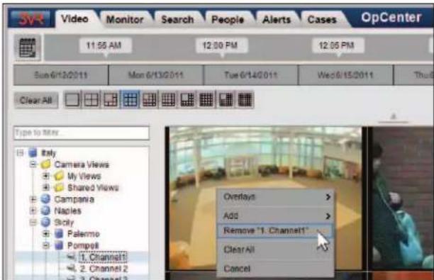
- To change the camera displayed in a specific video player, right-click the player, select Add>, then click Add "[Camera Name]".

Note
The Add "[Camera Name]" menu will list all cameras connected and enabled on the active appliance.
- To add a camera to the first available video player, right-click the camera name in the camera tree and select Add "[Camera Name]".
- To load all cameras in a camera group, right-click the group in the camera tree and select Add all cameras in "[Group Name]".
- To load all cameras connected to an appliance, right-click the appliance and select Add all cameras in "[Appliance Name]".


Removing Cameras
There are several ways to stop streaming a camera that is currently playing in the Video panel:
- To remove a specific camera, right-click the video player and select Remove "[Camera Name]".
- To remove all cameras belonging to a camera group, right-click the group in the camera tree and select Remove all cameras in "[Group Name]".
- To remove all cameras from a specific appliance, right-click the appliance in the camera tree and select Remove all cameras in "[Appliance Name]".
• To remove all currently selected cameras:
Right-click anywhere in the camera tree or video player grid and select Clear All.
Another way to clear all selected cameras is to click the Clear All button, located to the left of the layout selector.

2.3 Camera Views
The camera views feature of the Video panel allows you to save a given layout and selection of cameras for later use.
Saving a New Camera View
To save the current layout as a view:
- In the camera tree, right-click the Camera Views folder.
- Select Save View.
- In the Save View dialog, type a name for the view in the View Name box.
- If desired, select [ ]Save as shared view to make this view accessible to all users.
- Click Save.


Loading a Saved View
To switch the layout of the Video panel to a saved view:
- Click the plus sign next to Camera Views, then click the plus sign next to My Views or Shared Views to display the saved views.
- Click and drag a view from camera tree to the video player grid to load the view in the Video panel.

Note
Another way to load a saved view is to right-click the view name and select Load "[View Name]".

Deleting a Saved View
To delete a saved view:
- Click the plus sign next to Camera Views, then click the plus sign next to My Views or Shared Views to display the saved views.
- Right-click the view to delete and click Delete "[View Name]".
- In the pop-up dialog, click Yes to confirm that the view will be permanently deleted.

Note
You can only delete views that you created.

2.4 Camera Overlays
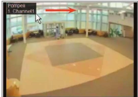
If you would like to display information about the camera on top of each video player, change the camera overlays with the following steps:
- Right-click anywhere in the video grid.
-
Select Overlays >, then choose an overlay from the sub-menu. The current overlay options are:
-
Camera Name
• Camera Number and Name
• Appliance Name, Camera Number, and Name - No Overlay

- By default, camera overlays are placed in the top-left corner of each video player. If desired, you can re-position the overlay by clicking and dragging the overlay box.
Start

End
2.5 Showing or Hiding the Video Timeline and Camera Tree
Both the camera tree and the video timeline may be hidden from view.
- Click the left-facing arrow to the right of the camera tree to hide the tree.
- Click the upward-facing arrow below the video timeline to hide the timeline.
To re-display the timeline and/or camera tree, click the arrows again.

2.6 Switching to Full Screen Mode
Switching the Video panel to full screen mode will display the selected cameras at maximum resolution.
-
To switch to full screen mode, click the full screen button (located above and to the right of the video player grid).
-
The Video panel will display in full screen mode.
-
There are two ways to exit full screen mode:
-
Move the mouse to the top of the screen to display the title bar, then click the X in the top-right corner.
- Press the escape key on your keyboard (Esc).

2.6 Video Playback Options
Two settings in the OpCenter Preferences dialog control the way live and stored video is streamed in the Video panel.
To access this dialog, click the 3VR button and select Edit Preferences from the menu.
Stored Video Fidelity Mode
When bandwidth is limited, video playback may lag into slow motion as OpCenter attempts to download and display each frame over a slow connection.
Using the Stored Video Fidelity Mode setting, you can instruct OpCenter to prioritize keeping up with regular speed playback over displaying every frame:
- Click Show every frame if bandwidth is adequate for all frames to be displayed without lagging.
- Click Drop frames as necessary for optimal playback in low-bandwidth environments. OpCenter will drop frames as needed to keep up with regular speed playback, resulting in choppier video when bandwidth is limited.

natural_image
Four-panel photo collage showing indoor scenes: a large circular plaza, a person climbing a floor, a modern office chair, and people in a room with computers (no visible text or symbols)
Live Video Alternate Streams
Enabling alternate streams allows you to optimize live video streaming in low-bandwidth environments by reducing the bandwidth required for live video, while preserving the quality of the video stored to disk.
When the box next to [ ]Enable alternate streams is checked, OpCenter will display live video using the alternate stream, if supported by the hardware. The configuration of the alternate stream depends on the type of camera:

- Analog cameras
Check the box next to [ ]Enable alternate streams to use the alternate stream for analog video, if available.
After clicking OK, use the slider bar at the top of the Video panel to prioritize frame rate (left) or quality (right).

Note
The following product series do not support alternate streams for analog cameras: E-Series, M-Series, first-generation S-Series (SRS-X30-XXXX model number).

• IP cameras
If an IP camera supports an alternate stream, the following settings will appear in the camera settings in 3VR System Manager:
Enable Alternate Stream?
Alternate Stream Frame Rate
Alternate Stream Frame Resolution
Edit these settings to enable and configure the alternate stream, then check the box next to []Enable alternate streams to use the alternate stream in OpCenter.
3. VIEWING LIVE AND STORED VIDEO
By default, the timeline control across the top of the Video panel displays a 30 minute time range. The time when the video you are viewing took place is overlaid on the timeline in the scrolling time slider.

Note
You can change the time range of the timeline in the OpCenter Preferences dialog (click the 3VR button > select Edit Preferences).
3.1 Live Video
When the Video panel loads, the selected cameras will begin streaming live video.
When video is live, the time slider displays the current time, and the slider moves forward along the timeline in real time.

The color of the time slider is blue when watching live video.

Tip
To quickly switch from viewing stored video to live video, click the go-to-live button located to the right of the timeline.
3.2 Stored Video
You can play back stored video in the Video panel in the following ways:
• To view video recorded earlier in the current day, click and drag the time slider left on the timeline.

After you release the mouse button, stored video will begin to play in all video players. When viewing stored video, the time slider will display the time the video was recorded. The time slider is white when viewing stored video.

• To view video recorded in the previous five days, click and drag the mouse on the dateline (located below the timeline). A smaller time slider will appear to assist you with picking a new start time.

To play back video from a specific date and time in the past, click the calendar button. Select the date from the calendar picker and adjust the time to the desired time, then click OK.

3.3 Video Playback Controls
Use the video playback controls below the timeline to control the playback of stored video in the following ways:

Pause: Pauses video playback.

Play: Restarts video playback.

Fast-forward: Fast-forwards through cached video*. Clicking the fast-forward button multiple times increases the fast-forward speed (.5x, 2x, 4x, 8x, or 16x).

Rewind: Rewinds through cached video*. Clicking the rewind button multiple times increases the rewind speed (.5x, 1x, 2x, 4x, 8x, or 16x).

Forward 15 minutes: Jumps playback 15 minutes forward on the timeline. If the current video time is less than 15 minutes behind real time, clicking this button will cause the Video panel to switch to live video.

Back 15 minutes: Jumps playback 15 minutes back on the timeline.
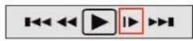
Frame forward: When video is paused, clicking this button skips ahead to the next frame.

Note
The white line below the time slider represents the portion of the video timeline that is currently cached. "Cached video" refers to video that has been downloaded from the 3VR VIP Appliance to your PC.

Dragging the time slider forward or backward through cached video will cause the video in the video players to fast-forward or rewind, respectively. When the time slider is moved to a portion of the timeline that is not cached, the video players will freeze on the last cached frame until more video is loaded.
4. PTZ CAMERA CONTROLS
4.1 Overview

Important
The features described in this section are available for IP PTZ cameras or analog PTZ cameras over a four-wire serial connection. Functionality may vary slightly when using some PTZ camera models or PTZ cameras where only a two-wire serial connection is supported. Contact your 3VR reseller for more information on your camera model if the behavior you observe is different than that described in this chapter.
PTZ camera control is available for live video streams in the Video panel or the Live Video tab of the Monitor panel.
Three PTZ control modes can be used to modify the current camera view:
- Compass Mode: a compass is displayed in the video player; clicking a chevron moves the camera in the selected direction
2. Click to Center Mode:
- Clicking on a point within the camera view re-centers the camera view.

Note
Move your mouse over the PTZ mode icons at the bottom of the video player to display the name of the mode in a tooltip.
• Drawing a box around a region with the mouse cursor zooms in and re-centers on the selected region.
• Using the slider bars tilts and zooms the camera.
- Joystick Mode: holding down the mouse button pans the camera in the direction of the mouse cursor.
4.2 Compass Mode
To change the camera's field of view using compass mode:
- Click the compass icon in the lower left corner of the video player to select compass mode.
- Click the chevrons in the compass to move the camera in that direction. The size of the chevron corresponds to the panning distance:
- Click the innermost chevron to move the camera a short distance.

natural_image
Interior view of a room with furniture and a wall-mounted device (no visible text or symbols)Start

natural_image
Interior scene with a white sofa, red pillow, and blue cushion in a dimly lit room (no visible text or symbols)End
- Click the middle chevron to move the camera an intermediate distance.
-
Click the outermost chevron to move the camera a larger distance.
-
Click and hold the mouse on any chevron to move continuously in the indicated direction. Clicking and holding down the innermost chevron will move the camera more slowly than the outermost chevron.
-
Use the slider bar along the left-hand side of the video player to zoom in and out.
4.3 Click to Center Mode
To change the camera's field of view using click to center mode:
-
Click the square icon in the lower left corner of the video player to select click to center mode.
-
To re-center the camera view, click the mouse anywhere in the video player to center the camera on that point.

natural_image
Interior scene with white sofa, blue cushion, and red pillow on dark background (no visible text or symbols)Start

End
• To tilt the camera up or down, use the slider bar on the right-hand side of the video player.
• To pan left or right, use the slider bar along the bottom of the video player.
- To zoom in or out, use one of the following options:
• Use the slider bar along the left-hand side of the video player.
- Click and drag the mouse to draw a box around a region of interest. The camera will zoom in the region.
4.4 Joystick Mode
To change the camera's field of view using joystick mode:
- Click the joystick icon in the lower left corner of the video player to select joystick mode.
- To move the camera using joystick mode, click anywhere in the current field of view and hold down the mouse button. The crosshairs will travel in the direction of the cursor at a speed proportional to the distance between the cursor and the crosshairs.

Start

natural_image
Interior view of an open-plan office with cubicles and workstations (no visible text or symbols)End
• To move slowly, click and hold closer to the crosshairs
• To move quickly, click and hold the mouse at a greater distance from the crosshairs
• To zoom in or out, use the slider bar along the left-hand side of the video player.
4.5 Preset Views
Selecting a Preset View
To move the camera to an existing preset view:
- Click Presets to display the presets menu.
- Select the preset view you wish to load.

Saving a New Preset View
To save a new preset view:
- Use click to center, compass, or joystick mode to move to the desired camera view.
- Click Presets to display the presets menu.
- Click Add Current View.
- Type the name of the new view in the pop-up dialog.
- Click Save to save the new view.
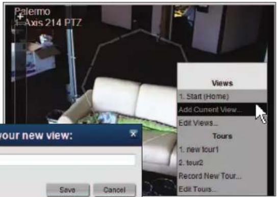
Editing a Saved Preset View
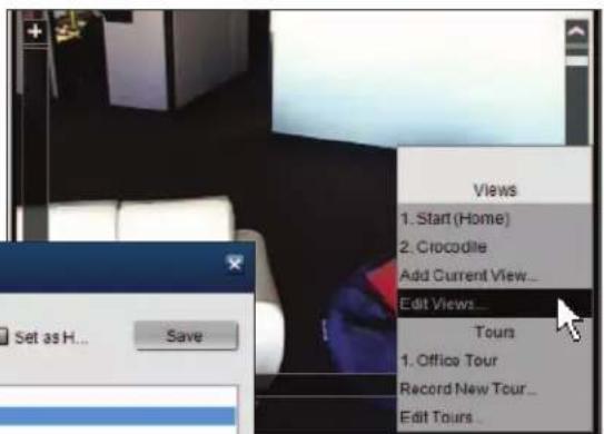
To modify or delete a preset view
-
Click Presets to display the presets menu.
-
Click Edit Views.
-
In the Edit Views window, select the name of the preset view to modify:
• To rename the preset view, type a new name for the view in the Name box, then click Save.
- To set the current view as the default view for this camera, select [ ]Set as Home Preset, then click Save.
• To delete the view, click Delete.
- Click Close to return to the Video panel.

4.6 Tours
Viewing a Saved Tour
To load a PTZ tour:
-
Click Presets to display the presets menu.
-
Click the name of the tour you wish to view.
The tour will continuously loop until manually stopped.
To stop the tour at any time, click the Click here to stop tour playback text at the top of the video player.
- To resume the tour, select the tour from the presets menu.

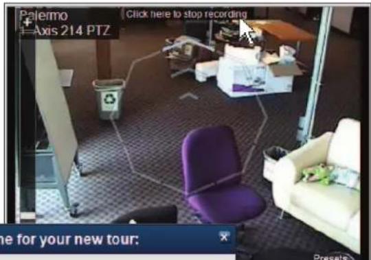
Recording a New Tour
To save a new PTZ tour:
-
Click Presets to display the presets menu.
-
Click Record New Tour.
-
Record your tour using the PTZ controls to change the camera view as desired.
-
When you are finished recording the tour, click the Click here to stop recording text at the top of the video player.
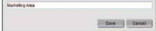
-
Type a name for the new tour in the pop-up window.
-
Click Save to save the tour.
Renaming or Deleting a Tour
To modify an existing PTZ tour:
-
Click Presets to display the presets menu.
-
Click Edit Tours.
-
In the Edit Tours window, select the name of the tour to modify:
• To rename, edit the name and click Save.
• To delete, click Delete.
- Click Close to return to the Video panel.

4.7 PTZ Camera Focus and Iris Control
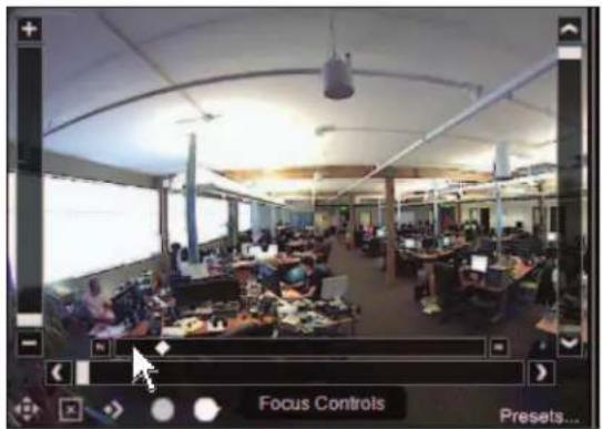
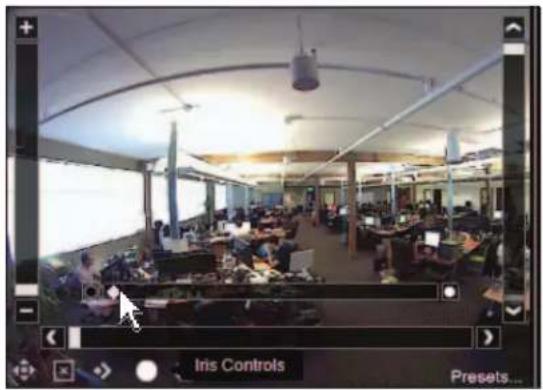
Some PTZ camera models allow for increased control over focus and brightness. For these cameras, clicking the Manual Focus Control or Manual Iris Control buttons at the bottom of the video player will display a slider bar to adjust focus or the size of the iris.
Manual Focus Control
By default, auto-focus will be enabled for all PTZ cameras. To manually control focus:
- Click the Focus Controls button at the bottom of the video player.

- To focus on objects nearer than the current focal point, click N, or move the slider bar to the left.
-
To focus on objects past the current focal point, click ∞ or move the slider bar to the right.
-
To resume automatic focusing, click the Focus Controls button again.
natural_image
Interior view of a modern open-plan office with multiple workstations and large windows (no visible text or signage)Manual Iris Control
By default, brightness will be automatically adjusted for all PTZ cameras. To manually control brightness:
- Click the Iris Controls button at the bottom of the video player.

- Click the box with the black circle to darken the field of view, or move the slider bar to the left.
-
Click the box with the white circle to brighten the field of view, or move the slider bar to the right.
-
To resume automatically adjusting brightness, click the Iris Controls button again.
natural_image
Interior view of an open-plan office with multiple workstations and a large projection screen (no visible text or symbols)5. DIGITAL ZOOM
3VR OpCenter 7.0 features the ability to zoom in on a region of interest in the camera video feed. This "digital zoom" feature adds PTZ-like functionality to fixed analog and IP cameras.
5.1 Entering Zoom Mode
You can zoom in on both live and stored video. There are two ways enter zoom mode:

Note
While digital zoom is supported for any non-PTZ camera, cameras with resolutions greater than 1 MP will produce the best results.
Zooming with the Mouse Scroll Wheel
- Click the video player to center the zoom, then use your mouse's scroll wheel to zoom in and out.

natural_image
Interior scene with people gathered around a table, one person using a laptop (no visible text or symbols)Start

natural_image
Interior scene with two people seated, one holding a smartphone, in a dimly lit room with blurred background (no visible text or symbols)End
Zooming While Holding the Ctrl Key
- While holding the Ctrl key, click and drag the mouse over the video feed to draw a box over the region of interest. Release the mouse button to zoom in on the region.

Start

natural_image
Close-up of a man in formal attire, focused on hand near ear (no visible text or symbols)End
5.2 Shifting the Zoomed Region
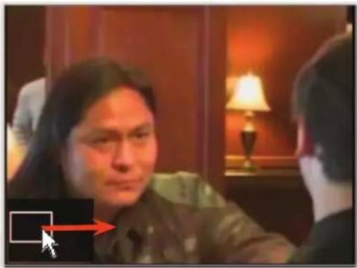
When a video player is in zoom mode, a zoom inset will appear in the bottom-left corner of the video player. The zoom inset contains a white box representing the current zoom level.
Shift the zoomed region by clicking and dragging the white box in the zoom inset.
natural_image
Close-up of a person in formal attire with blurred background (no visible text or symbols)Start

natural_image
Interior scene with people in a hallway, one person seated and another standing, no visible text or symbolsEnd
You can also nudge the zoomed region up, down, left, or right using the arrow keys on your keyboard.
5.3 Exiting Zoom Mode
You can exit zoom mode in one of two ways:
• Double-click the zoomed video player.
• Press the escape key (Esc).
6. OPENING A SECOND VIDEO PANEL
The OpCenter Video panel supports a maximum of 36 video players on-screen at one time. However, you may open a second instance of the Video panel to display additional cameras on a secondary monitor.
- To open the Multi-Screen Video Panel, click the multi-screen button ☐
- Drag the Multi-Screen Video Panel to the secondary monitor.
- Select cameras for the Multi-Screen Video Panel according to the instructions in section 2.2.
- Repeat steps 2-3 for any additional monitors.

Notes
The multi-screen button will be grayed out when there are no additional monitors available for multi-screen display.
Streaming video on multiple displays increases the system resources required to run OpCenter, beyond the minimum specifications. See Chapter 1: OpCenter Basics for more information.

7. PANORAMIC STITCHING
The Stitched Video Viewer allows you to choose up to four cameras and arrange the video feeds into one seamless view. Although any cameras may be used in a stitched view, this feature is most useful for panoramic cameras with multiple lenses.
7.1 Creating a New Stitched View
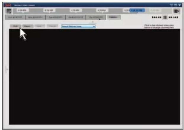
- To open the Stitched Video Viewer, click Stitched Video.

- In the Stitched Video Viewer, click Edit.
-
When you are in Edit mode, the camera tree will appear to the left of the video players.
-
Select a camera for each player by dragging and dropping the camera name on to the player (or using one of the other methods for selecting cameras; see section 2.2 of this chapter for details).
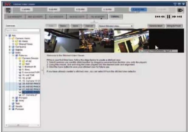
- After you are finished selecting cameras, click and drag the video players to re-position them. To change the layering of the video players, use the Send to Back and Bring to Front buttons.
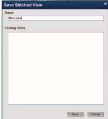
- To save the stitched view, click the Save button.
- Enter a name for the stitched view in the Name text box, then click Save.


natural_image
Blank white image with no visible content, text, or symbols7.2 Loading a Saved Stitched View
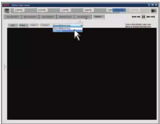
- In the Stitched Video Viewer, click the Select Stitched View drop-down menu.
- Select one of the saved stitched views to load it.
- To zoom in on a stitched view, click the video feed.
A purple zoom box will appear. Move the zoom box to the region of interest to zoom.

8. EXPORTING VIDEO AND IMAGES FROM THE VIDEO PANEL
8.1 Exporting Video

Note
If continuous recording is not enabled on a camera, only video associated with events will be available for export.
Use the following steps to export video from the Video panel:
- Click Export.

-
Select the cameras to export by clicking the check box beside each camera name in the camera tree.
-
When connected to a single VIP appliance, the camera tree will display the list of cameras on the system.
- When connected to a VIP Enterprise, the camera tree will show cameras from all systems on the Enterprise, organized first by region and then by appliance.

Note
The cameras that were streaming in the Video panel will be pre-selected in the camera tree.

-
Specify the Start Time and End Time for the video export.
-
To change the date, click the calendar icon to display the calendar picker. Click the date for export.
- To change the time, click the hours, minutes, seconds, or AM/PM and type new values (or press the up and down arrow keys on your keyboard).

- Select the location where you wish to save the exported video from the Location drop-down menu.
If the cameras you are exporting are on a 3VR VIP Appliance with a local drive connected, the drive letter(s) will be listed below the appliance name in the Location drop-down list.
- To create a new folder in the directory, select []Create new folder and type the new folder name.
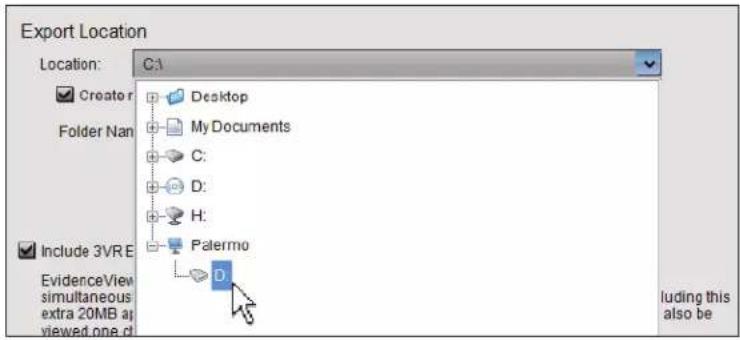
- To include 3VR Evidence Viewer, select [ ]Include 3VR Evidence Viewer Application. Including Evidence Viewer will allow the recipient of the video to play back cameras simultaneously, but the file size of the export will increase by approximately 20 MB.

Details
See Chapter 9: Exported Evidence for more information about viewing exported video.
- Click Export to export all available video from the selected cameras over the specified time range.
- While the export is underway, the progress of the export will be displayed in the Status column.
- If there is a problem exporting video from any of the selected cameras, the Status column will display an error. Select the camera to view more information about the error.

- When exporting is complete on all cameras, click Close to return to the Video panel.

Important
Exported video files are large. For cameras using the default resolution, frame rate and quality settings*, for each camera included in the export, each minute of video will be about 1 MB.
For example, if you are exporting 15 minutes of video from 16 cameras, the folder containing exported video will be around 250 MB in size if video is recorded at the default settings. If the frame rate is increased to 10 fps, or if the video resolution is increased to 2-CIF, the folder containing the exported video will be 500 MB.
* Default analog camera settings: Resolution = CIF, Frame Rate = 5 fps, Quality = Medium
8.2 Saving a Single Frame as an Image
Use the following steps to save a single frame from stored video to your computer or an external drive as an image:
- Click the pause button to pause playback on the frame of interest.
- Right-click the paused video player and select Save Image.
- Select the directory or drive where you wish to save the image file.
- Edit the file name if desired.
- Click Save to save the image.

CHAPTER 3
Monitor Panel
-
GETTING STARTED WITH THE MONITOR PANEL 50
-
VIEWING EVENTS 51
2.1 Event Card Types 51
2.2 Event Video 52
2.3 Event Details 53
- CUSTOMIZING THE MONITOR PANEL 54
3.1 Changing the Time Interval 54
3.2 Changing the Appearance of Event Cards and Event Images 55
3.3 Showing or Hiding the Event Editor and Video Player 56
- USING THE CAMERA SELECTOR 56
4.1 Viewing Camera Names 56
4.2 Selecting Cameras Individually 57
4.3 Selecting Multiple Cameras and Camera Groups 57
4.4 Creating a Camera Group 58
4.5 Editing or Deleting a Camera Group 58
-
VIEWING EVENT VIDEO IN THE POP-UP VIDEO PLAYER 59
-
VIEWING LIVE VIDEO IN THE MONITOR PANEL 59
-
EXPORTING IMAGES 60
7.1 Image Quick Save 60
7.2 Saving Images to an Event Card 60
7.3 Enhancing Images 60
7.4 Exporting Images 61
7.5 Printing Images 61
7.6 Emailing Images 62
- EXPORTING EVENTS 63
8.1 Printing Events 63
8.2 Emailing Events 63
8.3 Exporting Events 65
1. GETTING STARTED WITH THE MONITOR PANEL
The OpCenter Monitor panel allows you to view events as they happen. You can specify which cameras to view, and what types of events are displayed.
-
Click the Monitor tab to go to the Monitor panel.
-
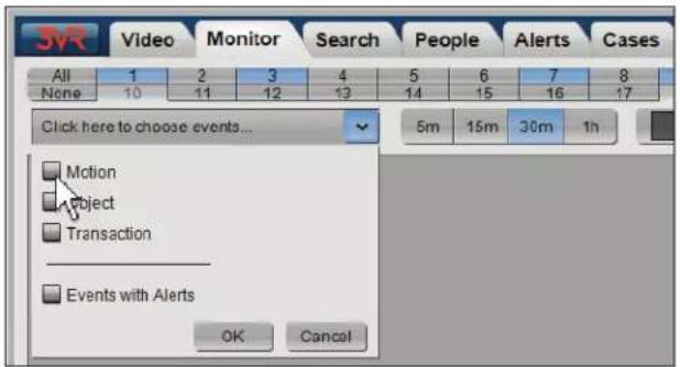
The camera selector (located at the top of the Monitor panel) allows you to filter events by camera or a set of cameras. Click All to view events from all cameras, or select cameras individually by clicking the camera number.
-
The first time OpCenter is launched on a PC, the Monitor panel will be blank, as no cameras or event types have been selected.
Click the arrow below the camera selector to open the event type drop-down menu. Check the box beside an event type to display events of that type. You must select at least one event type.
Select [ ]Events with Alerts to display only events that have triggered an alert.

Notes
1) Only event types applicable for the selected cameras will appear in the event type menu.
2) See Chapter 5: Alerts Panel for more information about alerts.
- Click OK.
- The Monitor panel will update to display event cards matching the specified criteria.
- To view an event, click the event card. The event card will turn blue, indicating it is currently selected.


2. VIEWING EVENTS
2.1 Event Card Types
Each event captured by the 3VR system is represented in OpCenter by an event card. Event cards are labeled with the type of event, date and time the event card was created, and other information about the event.
3VR's open and rapidly expanding platform permits an unlimited number of possible event types, as events can be generated by integration with external systems (e.g. transaction, access control, POS, etc.) and analytics plug-ins in addition to basic video recording. However, the following event types are available by default on all 3VR VIP Appliances:
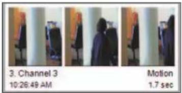
Motion Event Cards
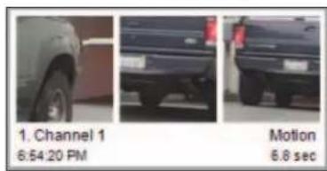
Motion events are created when the system detects movement in a camera's field of view. All motion event cards contain the following elements in storyboard view:
a. Images: each motion event card displays up to three still frames from the event:
b. Camera number and name: the number and name of the camera that captured the motion event.
c. Event start time: the time that motion was first detected by the camera.
d. Event duration: the length of time continuous motion was detected.
Face Event Cards\*
A face event card is generated when the system finds a face on a camera with face recognition enabled. All face event cards contain the following elements in storyboard view:
a. Face image: the best image of the individual's face.
b. Camera: the number and name of the camera that captured the face event.
c. Event time: the time the face was detected.


Note
Face events will not appear unless facial surveillance has been enabled and configured on one or more cameras.
External Input/Alarm Event Cards
Alarm events are generated when OpCenter receives an alarm input signal from a digital I/O device connected to the appliance. All alarm event cards contain the following elements in storyboard view:
a. Event image: a single image from the camera associated with the alarm.
b. Camera: the number and name of the camera that captured the alarm event.
c. Event time: the time the alarm event was triggered.
d. Alarm name: the name of the alarm.


Reference
See the 3VR VIP Appliance Installation and Configuration Guide for information on external alarm configuration.
Alert Event Cards
Alert events are events of any type that meet user-defined criteria for an alert, such as a targeted face or motion occurring during a certain time of day. Event cards for events that have triggered an alert will display a stripe at the top with the color of the alert.

Reference
See Chapter 5: Alerts Panel for more information about alerts.
Note Event Cards
Note events are events of any type to which a user has attached a note. Event cards for note events will be marked with the note label.

Reference
See Chapter 8: Notes for more information about notes and note labels.


2.2 Event Video
To view the video clip and other details of an event, click the event card.

More
Double-click the event card to play back the event video at full resolution in a separate window. See section 5 for details.

Note
You can disable automatic playback of event video from the Video page of the OpCenter Preferences dialog (click the 3VR button > Edit Preferences).
Use the video playback controls below the timeline to control the playback of stored video in the following ways:

Pause: Pauses video playback.


Play: Restarts video playback.

Fast-forward: Fast-forwards through video. Clicking the fast-forward button multiple times increases the fast-forward speed (.5x, 2x, 4x, 8x, or 16x).

Rewind: Rewinds through video. Clicking the rewind button multiple times increases the rewind speed (.5x, 1x, 2x, 4x, 8x, or 16x).
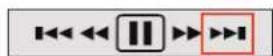
Forward 15 minutes: Jumps playback 15 minutes forward on the timeline. If the current video time is less than 15 minutes behind real time, clicking this button will cause the Video panel to switch to live video.

Back 15 minutes: Jumps playback 15 minutes back on the timeline.

Frame forward: When video is paused, clicking this button skips ahead to the next frame.
2.3 Event Details
When an event card is selected, details about the event may be viewed in the event editor, located below the video player.
Click the tabs in the event editor to view or edit the following properties:
- Notes
Click the Notes tab of the event editor to view the notes that have been added to an event, or to add a new note.

Reference
See Chapter 8: Notes for more information about viewing and editing notes.

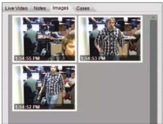
- Images
For a face event, the best images of the person's face will automatically be saved in the Images tab of the event editor.
Frames may be saved manually to the Images tab from other event types using the Save Frame button (see section 7.2 of this chapter).
- Person
If a face event has been matched to a person in the 3VR system, the person's details will be displayed in the Person tab of the event editor.
You may also create a new person from a face event from the Person tab.


Reference
See Chapter 7: People Panel for more information about creating people from face events.
- Properties
Custom fields may be viewed or edited from the Properties tab of the event editor.

Reference
See the document Managing Custom Fields to learn more about creating and editing custom fields.

- Cases
Add a selected event to a case from the Cases tab of the event editor.
You can add the event to an existing case, or create a new case with the current event card added as the first piece of evidence.

Reference
See Chapter 6: Cases Panel for more information about cases.
- Alerts
Events that trigger an alert will show details about the alert in the Alerts tab of the event editor.
- Details
Certain event types have automatically generated data that will appear in the Details tab of the event editor.
For example, alarm events show the name of the alarm.


3. CUSTOMIZING THE MONITOR PANEL
3.1 Changing the Time Interval
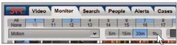
Use the time interval buttons at the top of the Monitor panel to specify the recent time frame to scan for events. You can view events that were generated within the last 5 minutes, 15 minutes, last 30 minutes, or 1 hour.
3.2 Changing the Appearance of Event Cards and Event Images
The event card format buttons allow you to customize the style and size of event cards. There are two event card styles, Storyboard View and Snapshot View.
Storyboard View displays event cards with full details.

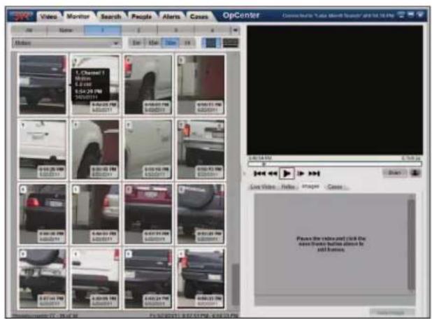
Snapshot View displays a single thumbnail image from the event.
When you are viewing event cards in Snapshot View, move the mouse over the event card to view the event details in an overlay.

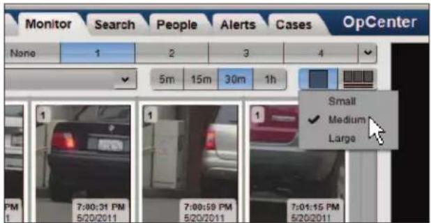
To change the appearance of event cards:
- Click the icon for the event card style.
- Select a size for the event cards (Small, Medium, or Large).
3.3 Showing or Hiding the Event Editor and Video Player
Both the video player and event editor may be hidden from view.
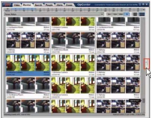
- Click the right-facing arrow on the left side of the event editor to hide the event editor and video player.
• To re-display the event editor and video player, click the arrow again.

4. USING THE CAMERA SELECTOR
4.1 Viewing Camera Names
To view a camera's name, move the mouse over the camera number without clicking. The camera name, number, and driver will be displayed as a tooltip.
To view all camera names and numbers at one time, click the drop-down arrow to the right of the camera selector. A menu will be displayed with all cameras and camera groups on the appliance.


4.2 Selecting Cameras Individually
OpCenter has two camera selection modes for selecting cameras individually, standard mode and toggle mode.
Standard Mode
In standard mode, clicking a camera number will add it to the selected cameras without removing your previous selection.

- Standard mode is the default camera selection mode in OpCenter. To return to standard mode from toggle mode, right-click anywhere in the camera selector and select Disable Toggle Mode.
- To select cameras in standard mode, click the camera number. The camera number will be highlighted in blue, indicating it is currently selected.
• To deselect a selected camera in standard mode, click the camera number again.
Toggle Mode
Toggle mode allows you to easily toggle between cameras. When a new camera number is clicked, the previous camera will be deselected.
- To switch to toggle mode from standard mode, right-click anywhere in the camera selector and choose Enable Toggle Mode from the resulting menu.
- To select a cameras in toggle mode, click the camera number. The selected camera numbers will be highlighted in blue.
• To deselect a camera in toggle mode, click a different camera number.

4.3 Selecting Multiple Cameras and Camera Groups
In both toggle and standard mode, you may select or deselect all cameras at once by clicking the All or None buttons to the left of the camera selector.
Another way to select multiple cameras is to right-click in the camera selector and choose a new camera arrangement option from the drop-down menu:
• Deselect the current camera
- Select only the current camera
- Select all cameras
• Deselect all cameras
- Select one of the camera groups configured on the appliance
To view all of the cameras and camera groups on the appliance, click the drop-down arrow next to the camera selector to display the camera selection menu.

• Select all cameras with Select All.
• Deselect all cameras by clicking Clear All.
- Select or deselect cameras or camera groups individually by clicking the check box next to each camera or group name.
When you have finished selecting cameras, click OK.

4.4 Creating a Camera Group
Use the following steps to create a new camera group:
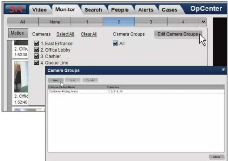
- Click the drop-down arrow to the right of the camera selector to display the camera selection menu.
- Click Edit Camera Groups.
- To create a new camera group, click New.
- Type a name for the new camera group.
- Select the camera numbers of the cameras to include in the camera group.
- If this camera group should be the default camera group in OpCenter, select []Default Camera Group.
- Click Save to save the camera group.

4.5 Editing or Deleting a Camera Group
- Click the drop-down arrow to the right of the camera selector to display the camera selection menu.
- Click Edit Camera Groups.
- To modify or delete a camera group, select the group name from the list.
• To edit the camera group, click Edit. Modify the Name field or which cameras are included in the group, then click Save.
- To delete the camera group, click Delete. In the resulting dialog box, click Delete again to confirm that the group should be removed.
- Click Close to close the camera selection menu.
5. VIEWING EVENT VIDEO IN THE POP-UP VIDEO PLAYER
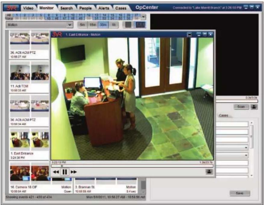
You can view video from an event in greater detail in the Pop-up Video Player.
- When an event card is selected, the Pop-up Video Player may be opened in one of the following ways:
• Double-click the event card or the event video player.
• Right-click the event card or video player and select Play in Separate Window.
-
The video clip will open in the Pop-up Video Player.
-
Use the controls at the bottom of the video player to pause, rewind, or fast-forward the video as desired.
- Click and drag the sides of the window to resize the video player.
- Click the native resolution button ▶ change the size of the player to match the native resolution of the camera.
- When you are finished viewing the video clip:
• Double-click a different event card to play back its video in the Pop-up Video Player, or
- Click the X in the corner to close the Pop-up Video Player and return to the Monitor panel.

More
You can zoom in on the video feed in both the event video player and Pop-up Video Player. See Chapter 2: Video Panel for more information.
6. VIEWING LIVE VIDEO IN THE MONITOR PANEL
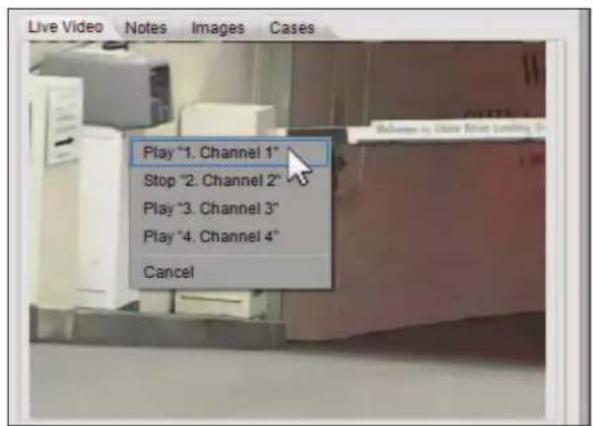
The Live Video tab of the event editor contains a single live video player, allowing you to keep an eye on one important camera while viewing event cards from a number of cameras.
There are two ways to begin streaming live video in the event editor:
- Select an event card, then click the Live Video tab in the event editor.
This will show the live video feed from the camera that captured the selected event.
- When no event card is selected, or to change cameras, right-click the video player and select a different camera from the list.
7. EXPORTING IMAGES
7.1 Image Quick Save
To quickly save a frame from an event as a JPG image:
- When event video is paused, right-click the video player and select Save Image.
- Choose a destination for the image file, then click the Save button.

7.2 Saving Images to an Event Card
Use the following steps to save a single frame from an event video clip. The image will be stored with the event and can be viewed from the Images tab of the event editor.
- Select an event card. The associated video clip will begin to play back in the video player.
- Click the pause button to pause playback.
- Click the frame forward button until the video player is paused on the frame you wish to save.
- When the video is paused, click the Save Frame button (represented by a picture icon) to save the frame as an image.
-
To view all images that have been saved from an event, click the Images tab of the event editor.
-
Double-click a thumbnail (or select the thumbnail and click the View Image button) to open a larger version of the image in the Image Details window.

7.3 Enhancing Images
After you have saved a frame from an event as an image, you can edit the image prior to exporting using OpCenter's built-in image editing controls. Image editing is performed in the Image Details window.
- Click an event card with associated images.
- Click the Images tab of the event editor.
- Double-click the thumbnail of the image you wish to edit (or select the thumbnail and click the View Image button).
- In the Image Details window, adjust the image as necessary using the following controls:

a. Click the Auto Levels button to auto-adjust the image brightness, contrast, and tonal range.
b. Use the sliders below the following properties to adjust the image quality manually:
• Lighten Shadows
- Darken Highlights
- Saturation
- Contrast
- Brightness
c. If the image is too grainy, click the Smooth button one or more times.
d. If the image lacks detail, you can add edges with the Sharpen button.

7.4 Exporting Images
After adjusting the image quality as desired (see section 7.3), export the image from the Image Details window with these steps:
- Click the Copy to button.
- In the Export Image dialog, click the drop-down arrow next to Location.
- Select the directory or drive where you wish to save the image. To create a new subfolder, select []Create new subfolder and type a new folder name.
- Select []Include event details in images to print information about the event as a caption on each image.
- Click Export.
- When the export completes, click Close.
7.5 Printing Images
You can print images directly from OpCenter from the Image Details window:
- Click the Print button.
- Type a title for the printout in the Title box.
- Select [ ]Event details to include the event type, starting date and time, ending date and time, and camera name with the image printout. Select Notes or Alerts to print any notes or alerts associated with the event.
- Choose which images to include on the printout: Only the Selected image or All images from the event.

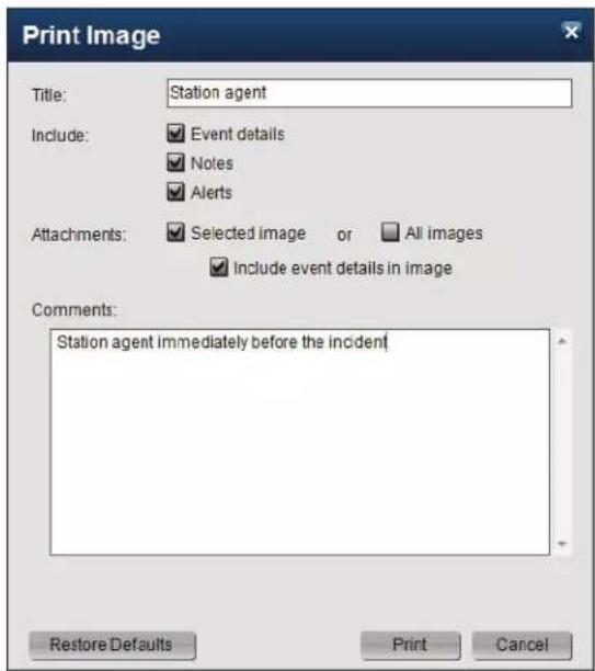
- Select [ ] Include event details in images to print information about the event as a caption on each image.
- Enter any additional comments you wish to include on the printout.
- Click Print.
7.6 Emailing Images

Note
The 3VR appliance must be configured with email server information in order to send outgoing messages.
You can email images directly from OpCenter from the Image Details window.
- Click Email.
- In the Email Image dialog, click the To button.
-
Specify the recipient(s) for the email in one of the following ways:
-
If the mail recipient is already listed in the address book, double-click the recipient to add them to the list of recipients.
- If the mail recipient is not listed, click Add to add a new recipient to the address book. Type the recipient's name and email address, then click Create.
-
To send an image to a one-time recipient, simply type the email address in the To box.
-
Click Done to return to the Email Image dialog.
- Type the subject line for the email in the Subject text box.
- Select the information you want to send along with the image:
• [ ]Event details
• [ ]Notes
• [ ]Alerts
- Choose which images to email: Only the [ ] Selected image or [ ] All images that have been saved to the event.
- Select []Include event details in images to print information about the event as a caption on each image.
- Select [ ]Video to attach video from the event to the email.
- Type any additional text to be sent in the body of the email in the Comments box.
- Click Send.


8. EXPORTING EVENTS
8.1 Printing Events
Use the following steps to print a summary of an event of interest:
-
Right-click the event card and select Print.
-
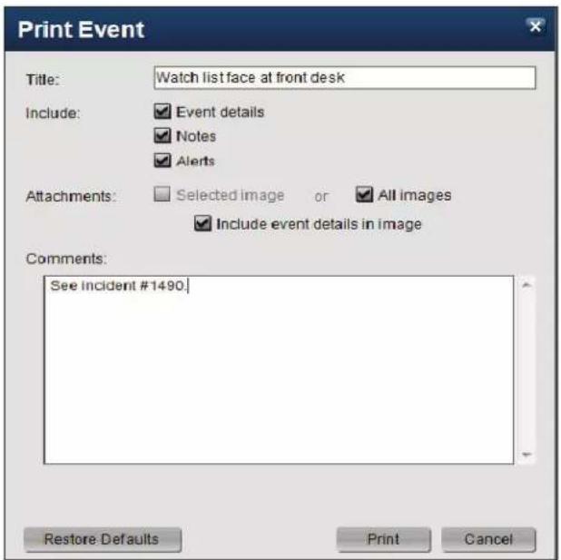
Enter a title for the printout.
- Select [ ]Event details to include the event type, starting date and time, ending date and time, and camera name with the event printout. Select Notes or Alerts to print any notes or alerts associated with the event.
- Select [ ] Include event details in images to print information about the event as a caption on each image.
- Enter any additional comments you wish to include on the printout.
- Click Print.
8.2 Emailing Events
Use the following steps to email an event directly from OpCenter:
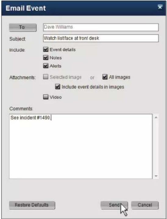
- Right-click the event card and select Email Event.


- In the Email Event dialog, click the To button.
-
Specify the recipient(s) for the email in one of the following ways:
-
If the mail recipient is already listed in the address book, double-click the recipient to add them to the list of recipients.
- If the mail recipient is not listed, click Add to add a new recipient to the address book. Type the recipient's name and email address, then click Create.
-
To send the email to a one-time recipient, simply type the email address in the To box.
-
Click Done to return to the Email Event dialog.
-
Type the subject line for the email in the Subject text box.
- Select the information you want to send along with the email:
• [ ]Event details
• [ ]Notes
• [ ]Alerts
- Select []Include event details in images to print information about the event as a caption on each image.
- Select []Video to attach video from the event to the email.
- Type any additional comments to be sent in the body of the email.
- Click Send.

8.3 Exporting Events
Exporting an event will convert the event details, video, and images to a file that may be viewed in a web browser (Mozilla Firefox, Internet Explorer, Chrome, or Safari). This allows the details of the event to be easily shared with law enforcement, management, or other interested parties.
Use the following steps to export one or more events from OpCenter:
- Select the event card to export, or hold the CTRL key and click event cards to select multiple events.
-
Right-click one of the selected event cards and select Export Event(s).
-
Click the drop-down arrow next to Location to select the directory or drive where you wish to save exported events.
- To create a new folder for exported events, select []Create new subfolder and type a new folder name.
- Click ( )All images, video and details so that images, video and details from exported events can be viewed in a web browser.
This format is ideal for sharing with law enforcement or other investigators, and also allows you to import the exported events into another VIP Appliance.
- Select []Include event details in images to embed details about the event in exported images.
- Click Export.
- When the export is complete, click Close.
- To view the exported events, navigate to the export folder in Windows Explorer and open the 3VR_events.xml file in a web browser.

Reference
See Chapter 9: Exported Evidence for more information about viewing exported events.
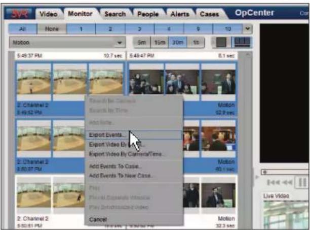
Export Event
Location:
C:\Users\krushton\Desktop

Create new subfolder
Folder Name:
Friday_Export
Files to Export
All images, video, and details
Images only
Video only
Export Options:
√ Include event details in images

Cancel
Export Event
Location
C:\Desktop

Create new subfolder
Folder Name:
Friday_Export
Files to Export
All images, video, and details
images only
Video only
Export Options
Include event details in images
Export complete.
Export
Close

CHAPTER 4
Search Panel
-
GETTING STARTED WITH THE SEARCH PANEL 68
-
BUILDING A SEARCH 69
2.1 Specify Date and Time Range 69
2.2 Select Cameras 69
2.3 Enterprise OpCenter | Select Appliances 70
2.4 Select Event Types 70
2.5 Reviewing Search Criteria and Running the Search 72
-
VIEWING SEARCH RESULTS 72
-
ADVANCED SEARCH OPTIONS 73
4.1 Searching for Correlated Events 73
4.2 Searching for Motion in a Region 74
4.3 Searching for Specific Faces 74
4.4 Sorting Search Results 76
- SAVING SEARCHES 76
5.1 Storing Search Criteria as a Saved Search 76
5.2 Running a Saved Search 77
5.3 Modifying or Deleting a Saved Search 77
- SEARCHING FROM AN EVENT OR PERSON CARD 78
6.1 Search for Camera 78
6.2 Search for Time 78
6.3 Search for Person 78
- EXPORTING SEARCH RESULTS 79
1. GETTING STARTED WITH THE SEARCH PANEL
Use the Search panel to find events recorded days, weeks, or months ago.
- To go to the Search panel, click the Search tab.
- Define the dates, days of the week, and time ranges to search for events. For example, you can set up a search for video recorded in the past month on a Thursday evening between 6 pm and midnight.
- Choose the cameras to include in the search. You must select at least one camera. Click All to select all cameras.

Note
Customers with a VIP Enterprise Appliance can search across multiple appliances on the Enterprise. See section 2.3 for details.
- Check the boxes under Events to specify the event types to search. You must select at least one event type.
- Click the Search button.
-
Events matching your criteria will be displayed in the Search panel results screen.
-
Select an event card to view the video clip and details associated with the event.


2. BUILDING A SEARCH
2.1 Specify Date and Time Range
The first step when selecting search criteria is to specify the period of time you want to search for events.
Date Range
- To search for events occurring within a common date range, click ( )Recent and click one of the pre-defined date range buttons, such as 1 day.
- To search for events during a specific date range, click ()Specify, and select a specific Start and End date for the search from the calendar picker.

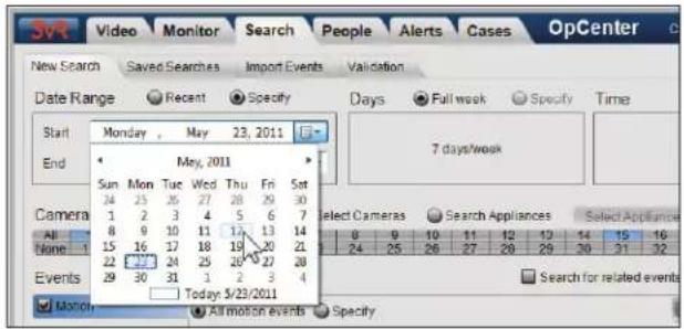
Days
If a Date Range of 1 week or longer has been selected, you can restrict the search to specific days of the week.
- Click ( )Specify and click the days to include to limit the search to specific days.
- Leave the Days option set to ( )Full week to search every day of the week.
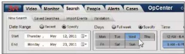
Time
If the Date Range specified is at least one day, you can restrict the search to certain times of the day:
- Click ( )Partial day to search for common time ranges like evening or working hours.
- Click ( )Specify to specify precise hours, minutes, and seconds to search.
• To include all 24 hours in the search, click ( )Full day.
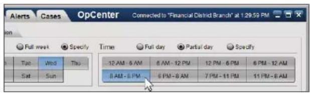

2.2 Select Cameras
Use the camera selector to specify which cameras to include in the search:

- Select cameras individually by clicking each camera number.
• To select all cameras on the appliance, click All. - To run the search on all cameras in a camera group, click the dropdown arrow at the end of the camera selector, then select the camera group name.

Reference
See Chapter 3: Monitor Panel for detailed instructions on using the camera selector, including creating camera groups.
2.3 Enterprise OpCenter | Select Appliances
By default, OpCenter will search for events from cameras on a single appliance. However, users connected to Enterprise OpCenter can search for events across multiple appliances at one time with the following steps:
- To search across appliances, select ( )Search Appliances.
- Click the Select Appliances button.
- In the appliance tree, check the box next to each appliance to include in the search.
- Click OK to return to the Search panel.
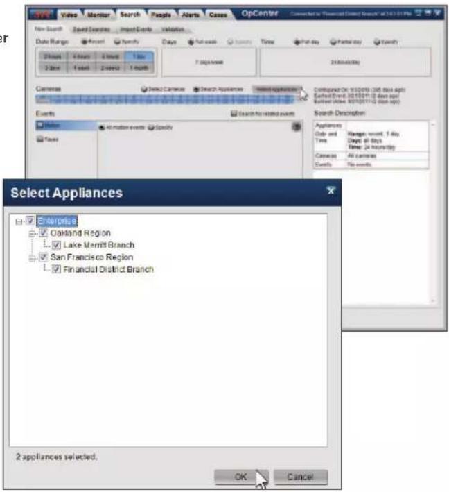
2.4 Select Event Types
The event selector displays the list of event types available on the appliance (or the active appliance, if you are connected to an Enterprise Appliance).
Check the box next to the event type(s) to include in the search. You must select at least one event type. The following event types are available by default on all 3VR VIP Appliances:
Motion Events
To search for motion events, check the box next to []Motion in the event selector, then click one of the following options:
- ()All motion events: returns all motion events matching the other search criteria.
- ()Specify: search for motion events that occurred within a specific part of the camera view. See section 4.2 for detailed information on searching for motion in a region.

Face Events\*
To search for face events, check the box next to [ ]Faces in the event selector, then click one of the following options:
• ()All faces: returns all face events matching the other search criteria.
- ()Specify: search for face events similar to known people or matching people from a group. See section 4.3 for detailed information on searching for specific faces.
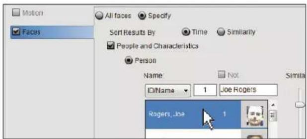
Alarm Events
If an external alarm system has been connected to the appliance and configured in System Manager, alarm events will be created when the alarm is triggered. To search for alarm events, check the box next to []Ext. Input/Alarm in the event selector, then click one of the following options:
- ()All Ext. Input/Alarm: returns all alarm events matching the other search criteria.
- ()Specify: allows you to search by the name of the alarm, for example "Store Alarm".

Alert Events
Search for events that triggered an alert by checking [ ]Events with Alerts in the event selector, then click one of the following options:
- ( )All events with alerts: returns all events that triggered an alert matching the other search criteria.
- ()Specify: select specific alerts from the list. Only events that triggered the select alert(s) will be returned.

Note Events
Search for events that have had notes added to them by checking [ ]Events with Notes in the event selector, then click one of the following options:
- ()All events with notes: returns all events with notes that match the other search criteria.
- ()Specify: select one or more note labels from the list. Only events with notes that were categorized with the selected note label will be returned.


Notes
1) Every event type that has ever existed on the appliance will appear in the Events list, even if events of that type are no longer being generated.
2) For information about event types generated by plug-ins (for example, transaction events or events generated by access control systems) please consult the plug-in documentation.
3) The Faces event type will not be listed unless facial surveillance has been enabled and configured on one or more cameras. Enabling face requires the system be licensed for the VIP Facial Surveillance analytic.
2.5 Reviewing Search Criteria and Running the Search
As you build the search, the selected search criteria will be added to the Search Description table on the right side of the Search panel.
When you are finished defining the search criteria, click the Search button to run the search.

3. VIEWING SEARCH RESULTS
After clicking the Search button, the results of the search will be displayed in the Search panel results screen.
The look and feel of the search results screen is similar to the Monitor panel. Click an event card to open the event video and details in the event editor.

To perform another search:
- Click Modify Search to return to the main screen of the Search panel with your current criteria still selected. The Modify Search button keeps your search settings so you can change or fine-tune them and perform the search again.
- Click New Search to return to the main screen of the Search panel with the search options reset to their default values.

4. ADVANCED SEARCH OPTIONS
4.1 Searching for Correlated Events
One of the features of the OpCenter Search panel is correlated search — the ability to search for events of a second type occurring around the same time as events of a primary type. For example, if you are investigating a break-in, correlated search allows you to search for face events captured around the same time as an alarm event. Or, you may want to search for motion events occurring around the same time as a face event to learn more about the context of the face event.
Use the following steps to set up a correlated search:
- To go to the Search panel, click the Search tab.
- Define the date range and cameras to search for events according to the steps in section 2.
- Under Event Type, check the box next to the primary event type, for example [ ]Face events.
- Check []Search for related events to load the secondary search window.
- Specify the period of time you wish to search for related events. By default, OpCenter will search 3 minutes before and after each primary event for events of the secondary event type.
- Specify the secondary event type to search, for example [ ]Motion events.
- The current search criteria will be summarized under Search Description.
- Click the Search button.
- Events that match the first set of search criteria will be displayed in the Search panel results screen.
Any events with correlated events of the secondary type will be displayed with a plus sign.
- Click the plus sign to display the related events.

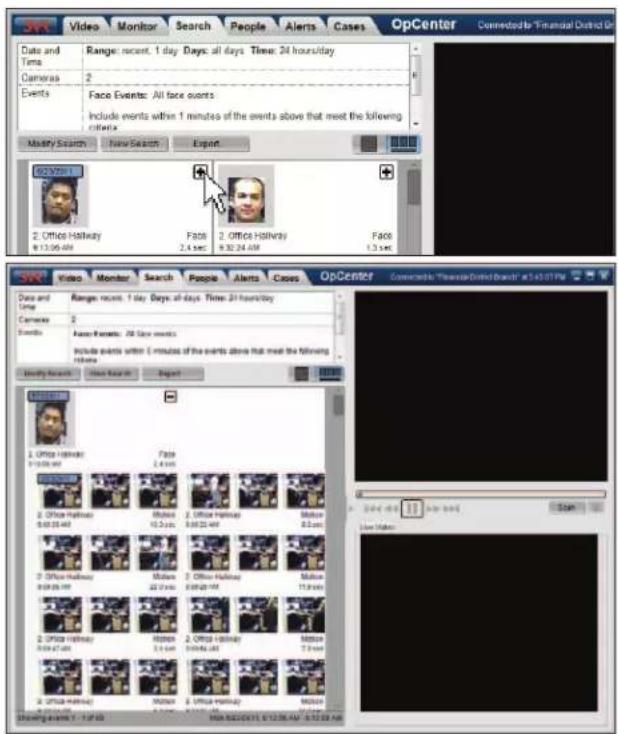
4.2 Searching for Motion in a Region
When setting up a search for motion events, choosing ( )Specify in the event selector allows you to search for motion recorded in a specific region of the camera view.
To search for motion in a region:
- Check [ ]Motion, then click ( )Specify.
- Check [] Motion in region.
- Draw a region to search for motion events:
Rectangular Region
- Click the square icon

aw a rectangular region.
- Click and drag the mouse on the video feed to draw the region.
Custom Region
- Click the complex shape icon to draw a custom region.
- Click the video feed multiple times to draw each anchor point for the custom region. Click your start point to complete the region.
4. Click Search.

Note
Searching for motion in a region is limited to one camera at a time. The Motion in region editor shows a single still frame from the video feed of the selected camera; to obtain a new frame, click Refresh.

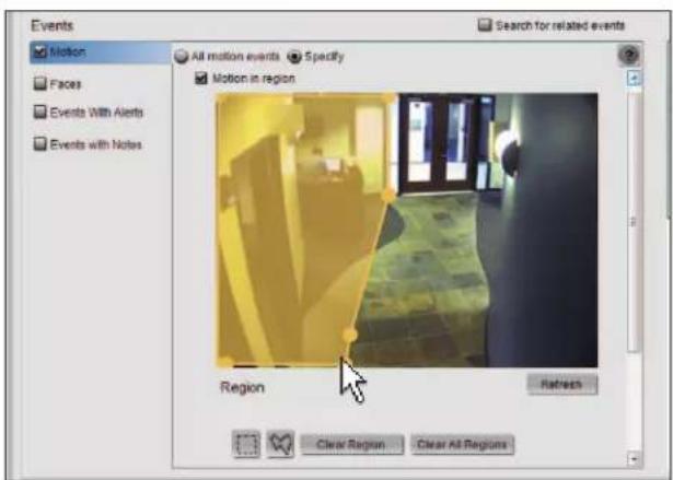
4.3 Searching for Specific Faces
When setting up a search for face events, choosing ( )Specify in the event selector allows you to further restrict the search to certain kinds of face events.
A. Searching for Faces Similar to a Person
Use the following steps to search for face events similar to a known person:
- Check []Faces, then click ()Specify.
- Check [ ]People and Characteristics, then click ( )Person.
- Scroll through the list of people to find the person you are searching for. Click to select that person.
-
Define the Similarity level to use for the search:
-
Selecting a higher similarity level will return results that are more likely to match the face you are searching for, but there will be fewer results.
- Selecting a lower similarity level will return more results, but more of those faces may not match the one you are searching for.
5. Click Search.
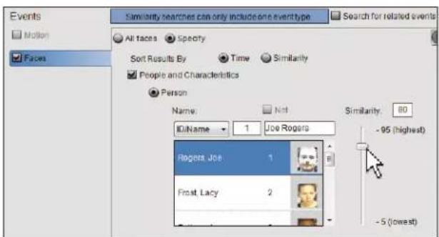
B. Searching for Faces Not Matching a Person
Use the following steps to search for face event that do not match a known person:
- Check [ ]Faces, then click ( )Specify.
- Check [ ]People and Characteristics, then click ( )Person.
-
Scroll through the list of people to find the person to exclude from the search. Click to select that person.
-
Check the box next to []Not.
-
Move the Similarity level scroll bar to 95 (Matches Only).
-
Click Search.

C. Searching for Faces Similar to Members of a Group
Use the following steps to search for face events similar to any of the people in a group:
-
Check [ ]Faces, then click ( )Specify.
-
Check [ ]People and Characteristics, then click ( )Characteristics.
-
Check [ ]Groups. Scroll through the list of groups and select the group to search for.
-
Define the Similarity level to use for the search:
-
Selecting a higher similarity level will return results that are more likely to match the face you are searching for, but there will be fewer results.
-
Selecting a lower similarity level will return more results, but more of those faces may not match the one you are searching for.
-
Click Search.

D. Searching for User-Defined Person Characteristics
Use the following steps to search for face events that have been tagged with user-defined properties, such as an employee ID:
- Check [ ]Faces, then click ( )Specify.
- Check [ ]People and Characteristics, then click ( )Characteristics.
- Check [ ]Person Properties and specify the search value.
- Click Search.


Note
Searching by employee ID, gender, and/or hair color will only produce useful results if these properties have been manually entered regularly and consistently. See Chapter 7: People Panel for more information on editing person details.
4.4 Sorting Search Results
There are two ways to sort the results of a search: by Time and by Similarity.
By default, OpCenter sorts search results by time. This is the most appropriate sort order when searching for motion events, alarm events, and other event types that are located using binary matching. Events of these types either fulfill the search entirely ("yes, it is an alarm event") or not at all ("no, is not an alarm event").
In contrast, certain other event types will return search results that fall on a spectrum, with results matching better ("more similar") or worse ("less similar") to the search criteria. Face events are a prime example of this type of search.
When searching for faces similar to a given face, OpCenter will search through all faces in the database and give each a similarity score, a numerical representation of how similar the face is to the search face. OpCenter will then return the set of face events that have similarity scores equal to or higher than the similarity value you specified in the Search panel (see section 4.3 for more information on searching for a specific face). For best results, search results returned by this kind of search should be sorted in order of similarity, not chronologically.
Sort order is specified when setting up a search. To change the sorting of search results for face events:
-
Under Events, check the box next to [ ]Faces to search for face events.
-
Click Specify.
-
Change the Sort Results By radio button to ( )Similarity. When the search results are displayed, the most similar events will appear first in the results.

5. SAVING SEARCHES
5.1 Storing Search Criteria as a Saved Search
If you frequently perform the same searches, you can save search criteria to make future investigations faster.
To save a search:
-
Click the Search tab to go to the Search panel.
-
Specify the search criteria as described on the previous pages.
-
Click Save.
-
In the Save Search dialog, enter a name for the search.
-
Click Save.

5.2 Running a Saved Search
To search for events using a saved search:
- In the Search panel, click the Saved Searches tab.
- Select the saved search to run from the list of saved searches.
- Click the Search button.

5.3 Modifying or Deleting a Saved Search
To modify a saved search:
- In the Search panel, click the Saved Searches tab.
-
Click to select the saved search you wish to modify from the list of searches.
-
To change the search criteria, click the Edit button. You will be returned to the main screen of the Search panel where you can modify the search parameters as desired. Click Save to store your changes.
• To delete the saved search, click Delete. In the pop-up that appears, click Yes to confirm the search should be deleted.

6. SEARCHING FROM AN EVENT OR PERSON CARD
You can quickly initiate a search for events with properties similar to an event or person of interest by right-clicking the event card or person card and selecting one of the following options from the right-click menu:
6.1 Search for Camera
Choosing this option will switch the user to the Search panel with the following criteria selected:
• Date Range: The same day as the source event.
• Time: A two hour interval surrounding the time of the source event.
- Cameras: The camera that captured the source event.
• Events: All event types checked.
6.2 Search for Time
Choosing this option will switch the user to the Search panel with the following criteria selected:
• Date Range: The same day as the source event.
• Time: A five minute interval surrounding the time of the source event.
- Cameras: The camera that captured the source event.
• Events: All event types checked.
6.3 Search for Person
Choosing this option will switch the user to the Search panel with the following criteria selected:
• Date Range: Recent: 1 day
• Time: Full day
- Cameras:
- If searching from a face event card, the camera that captured the face event will be pre-selected.
• If searching from a person card in the People panel, all cameras will be pre-selected.
- Events: [ ]Faces checked with ( )Specify selected, searching for faces with a similarity factor of 80.


7. EXPORTING SEARCH RESULTS
Export events from the Search panel search results screen in one of the following ways:
- Select the event(s) to export, then click the Export button at the top of the screen. In the Export Event dialog, specify the directory on your computer where the files should be saved, then click Export.
- Select the event(s) to export, then right-click one of the selected event cards and choose Export Events from the menu. In the Export Event dialog, specify the directory on your computer where the files should be saved, then click Export.
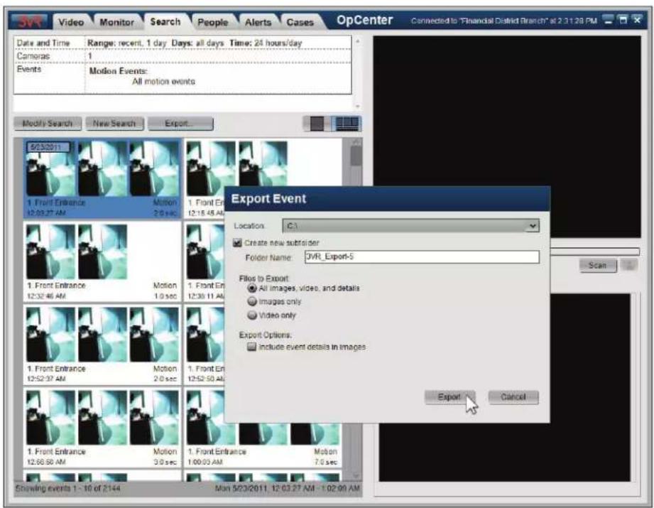

Reference
Exporting event cards from the search results screen is an identical procedure to exporting events from the Monitor panel. Please see Chapter 3: Monitor Panel for detailed information on exporting events and event images.
CHAPTER 5
Alerts Panel
- GETTING STARTED WITH THE ALERTS PANEL 82
- CREATING AN ALERT 83
2.1 Set Alert Name and Color 83
2.2 Select Days and Times 83
2.3 Select Cameras 83
2.4 Select Event Types 84
2.5 Specify Alert Action 84
2.6 Outline Alert Response Procedure 84
2.7 Save and Enable the New Alert : 85 - ALERT ACTIONS 86
3.1 Viewing Alert Actions 86
3.2 Configuring a New Email Alert Action 86
3.3 Creating a New Settings Change Alert Action 88 - VIEWING ALERT EVENTS 89
1. GETTING STARTED WITH THE ALERTS PANEL
Using the Alerts panel, you can instruct the 3VR appliance to perform a specified action when video is recorded that matches certain criteria.
For example, you can set up an alert that will email management and increase video recording quality whenever motion is detected in a restricted area after hours.
- To go to the Alerts panel, click the Alerts tab.
- The main screen of the Alerts panel displays the list of alerts that have been created on the appliance. Click an alert to view a summary of its properties.
- To create a new alert, click New.
OpCenter will switch to the alert editing screen.

Reference
See section 2 of this chapter for detailed information about alert configuration. See section 3 to learn how to define alert actions.
- Type a name for the alert.
- Select a color for the alert.
- Specify the days and hours the alert should be active.
- Select the cameras for the alert.
- Select the event types to include in the alert.
- Check the boxes next to one or more alert Actions to carry out when the alert is triggered.
- Type an alert response procedure. This text will be included with the alert and posted on events that trigger the alert.
- Click Save to save the new alert.
- The alert will be added to the list of alerts displayed in the main view of the Alerts panel. Click the check box next to the alert to enable it.

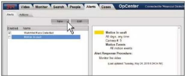

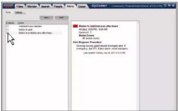
2. CREATING AN ALERT
- Click the Alerts tab to go to the Alerts panel.
- To create a new alert, click New.
- OpCenter will switch to the alert editing screen. From here, you can edit a number of properties for the alert, outlined in detail in the following sections.
2.1 Set Alert Name and Color
- Type a name for the alert in the Name text box.
- Click on the default color block (red) to display the color selector. Use the scroll bar to view additional colors.
Click a color block to select a color. The color you select for the alert will appear across the top of an event card that triggers the alert.


2.2 Select Days and Times
Days
- Choose ( )Specify and click the days to include to enable the alert only on certain days.
- Leave the Days option set to ( )All days to run the alert on every day of the week.
Time
- Select ( )Specify to enable the alert during specific hours.
• To include all 24 hours in the alert, select ( )Any time.
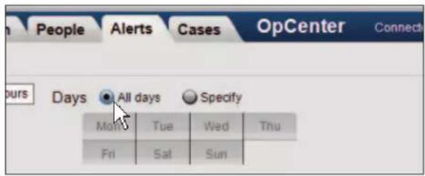

2.3 Select Cameras
Use the camera selector to specify which cameras to include in the alert:

- Select cameras individually by clicking each camera number.
• To select all cameras on the appliance, click All. - To run the search on all cameras in a camera group, click the dropdown arrow at the end of the camera selector, then select the camera group name.

Reference
See Chapter 3: Monitor Panel for detailed information about the camera selector, including defining camera groups.
2.4 Select Event Types
The event selector displays the list of event types available on the appliance (or the active appliance, if you are logged in to Enterprise OpCenter).
Check the box next to the event type(s) of interest under the Events header. You must select at least one event type.
By default, the alert will be run on all events of the selected type. However, most event types have additional properties available with the ( )Specify radio button in the event selector.
For example, use the following steps to create an alert based on faces similar to people that have been added to a watchlist:
- In the event selector, check the box next to []Faces.
- Select ( )Specify.
- Check [ ]People and Characteristics, then select ( )Characteristics.
- Check [ ]Groups.
- Check the box next to the name of the watchlist group.

Notes
1) See Chapter 4: Search Panel for detailed information about configuring the ( )Specify options for motion events, face events, and other built-in event types. For event types generated by plug-ins (for example, transaction events) please consult the plug-in documentation.
2) The Faces event type will not be listed unless facial surveillance has been enabled and configured on one or more cameras. Enabling face requires the system be licensed for the VIP facial surveillance analytic.
2.5 Specify Alert Action
When defining the alert, you can instruct the 3VR appliance to carry out certain actions when an alert is triggered. The alert actions that have been defined on the appliance are listed in the Actions box.
Check the box beside each action that should be performed when this alert is triggered.

More
See section 3 for instructions on defining alert actions.

2.6 Outline Alert Response Procedure
Enter text into the Alert Response Procedure box to include instructions or helpful information for the alert responder.
This text will appear with other information about the alert when alert event card is clicked in the Monitor panel, Cases panel, or Search panel results screen.

2.7 Save and Enable the New Alert:
- After you are finished defining the criteria for the alert, click Save to save the new alert.
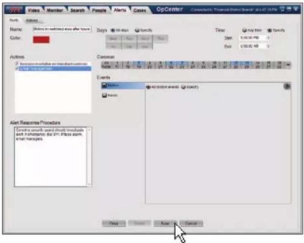
- The alert will be added to the list of alerts displayed in the main view of the Alerts panel. Click the check box next to the alert to enable it.
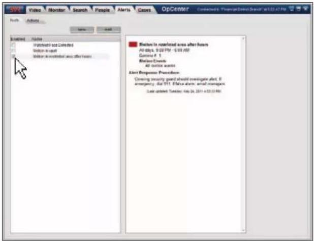
3. ALERT ACTIONS
Alert actions can be created to email key security personnel, change recording settings, or modify the maximum amount of bandwidth a camera can use when an alert is triggered.
3.1 Viewing Alert Actions
-
To view and edit alert actions, click the Alerts tab, then the Actions tab.
-
Select an action from the list of alert actions. A description of the alert action will appear in the text box to the right of the actions list.
The information displayed depends on the type of alert action. Settings change alert actions will display:
- Scheduled Values: the settings that will take effect when the alert is triggered.
- Post-Alert Recording Period: the settings change will remain in effect for this many seconds after the alert is triggered.
- Cameras: Which cameras will have modified settings during the post-alert recording period.
Email alert actions will show the following fields:
• To Addresses: the list of recipients of the alert email.
- Subject: subject line of the email that will be sent when the alert is triggered.
• Body: content of the email that will be sent when the alert is triggered.
- Include: lists information and images that will be included with the email.
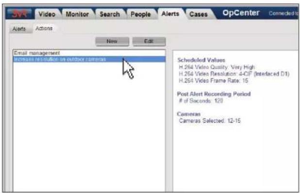
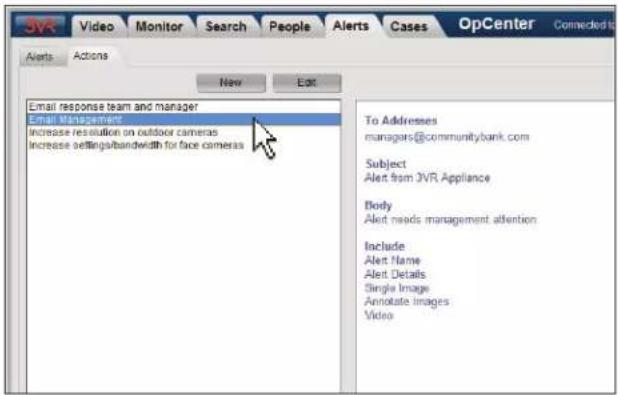
3.2 Configuring a New Email Alert Action
Use the following steps to create a new email alert action. Alerts configured with the action will send an email when the alert is triggered.
- To view and edit alert actions, click the Alerts tab, then the Actions tab.
- Click New.
-
Click ( )Email, text message, or page.
-
Type an Action Name to identify the action in the Alerts panel.

-
Click the To button to display the Email Recipients dialog.
-
Specify the recipient(s) for the email in one of the following ways:
-
If the mail recipient is already listed in the address book, double-click the recipient to add them to the list of recipients.
-
If the mail recipient is not listed, click Add to add a new recipient to the address book. Type the recipient's name and email address, then click Create.
-
Click Done.

- Type the subject line for the email in the Subject box.
- Type a message for the email body.
- Select the information you want to send in the alert email:
• [ ]Alert name: includes the alert name in the body of the message.
• [ ]Alert details: includes a brief summary of the alert criteria in the body of the message.
- [ ]Single image: emails only the image that triggered the alert or [ ]All images: includes all images from the event.
• [ ]Add event details in images: embeds information about the event in each image saved from the event.
• [ ]Send verification image: includes the reference image for face events that match to a known person.
• [ ]Video: includes the video file associated with the event as an attachment.
- [ ]Send additional early email when event opens: by default, alert emails are sent at the conclusion of an alert event. Check this box to send a message when the event opens as well as when it closes.
- Click the Save button to save the alert action.

3.3 Creating a New Settings Change Alert Action
Use the following steps to create a new settings change alert action. Alerts configured with the action will change recording settings and/or bandwidth consumption on specified cameras when the alert is triggered.

Important Notes
1) Settings change alert actions may only be configured for one model of camera at a time. Analog cameras are considered one type and may be configured together regardless of make/model.
2) The same Maximum Bandwidth values must be used for all alert response actions that will take effect at the same time.
- To view and edit alert actions, click the Alerts tab, then the Actions tab..
- Click New.
-
Click ()Settings change.
-
Type an Action Name to identify the action in the Alerts panel.
To modify the camera recording settings when the alert is triggered:
- Check [ ]Recording Settings.
- Select cameras from the camera selector by clicking the camera number. Each alert action may only be applied to one camera model (see important note, above). A warning message will be displayed if you select incompatible cameras.
- Configure the modified settings which will take effect when the alert is triggered. Depending on the selected camera model, different configuration options will be available. Only settings that apply to the selected camera model will be displayed.
To modify the maximum network bandwidth available to the system after an alert is triggered:
- Select [ ]Maximum Bandwidth.
- Enter the maximum network bandwidth that should be made available to the 3VR appliance after an alert has been triggered into the Maximum Bandwidth (Kbits/sec) box.
To allow unlimited bandwidth usage, enter 0.
- The Apply settings for [ ] seconds after the alert box controls the duration that the modified settings and/or maximum bandwidth will take effect after an alert is triggered. 120 sec
will be entered by default, but you may enter a new value in the range of 1 to 99,999 seconds.
- Click Save to create the new alert response action.
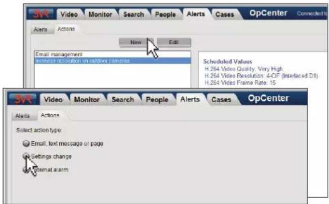
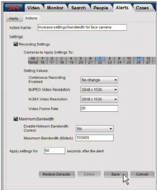
4. VIEWING ALERT EVENTS
When an alert is triggered, the event that triggered the alert will be labeled with colored bar across the top of the event card.
To view information about the alert associated with an event card:
- Click the event card.

- The event editor will open automatically to the Alerts tab with details about the alert.

CHAPTER 6
Cases Panel
1. GETTING STARTED WITH THE CASES PANEL 92
1.1 Cases Panel Overview 92
1.2 Cases Panel Layout 92
- WORKING WITH CASES 93
2.1 Viewing an Existing Case 93
2.2 Opening a New Case 93
2.3 Editing a Case 95
2.4 Deleting a Case 95
- BUILDING A CASE 95
3.1 Adding Events to a Case 95
3.2 Adding a Person to a Case 96
3.3 Removing Evidence from a Case 96
4. ADDING SUPPORTING DOCUMENTS AND NOTES TO A CASE 97
4.1 Adding a Document to a Case 97
4.2 Working with Documents 98
4.3 Adding Notes to a Case 99
- EXPORTING A CASE 99
1. GETTING STARTED WITH THE CASES PANEL
1.1 Cases Panel Overview
The OpCenter Cases panel provides a centralized interface for managing evidence (events, people, documents, etc.) relevant to an ongoing investigation. Using a case to manage an investigation allows you to draw links between pieces of evidence, quickly view a summary of an ongoing case, and easily share the case details and supporting evidence with management or law enforcement.
OpCenter cases can be either public or private. Public cases are visible to all users with access to the Cases panel, allowing collaboration across the entire organization. In contrast, private cases are only visible to the creator and the assignee, a critical feature when carrying out an internal investigation.
Furthermore, events added to a case are permanently protected from the periodic deletion of old data that occurs when the 3VR appliance runs low on disk space. This ensures that critical surveillance is available when it is needed.

Note
To view, create, and modify cases on a VIP Appliance that is connected to an Enterprise, be sure to enter the Enterprise Appliance IP address in the Appliance field when logging in to OpCenter. If you are logged in to one of the individual appliances instead, the OpCenter Cases tab will not be visible.
1.2 Cases Panel Layout
- Click the Cases tab to go to the Cases panel.
- The main view of the Cases panel displays the list of cases on the system.
-
If there are a large number of cases, use the following methods to filter the list:
-
Use the Filter by User dropdown menu at the top of the Cases panel to filter the cases by the case creator or assignee. By default, this dropdown is set to My Cases. To view all cases, change the Filter by User menu to All.
- Sort the list of cases by their properties by clicking the column headers. For example, click the Name column header to sort alphabetically by case name (A-Z). To sort in reverse order (Z-A), click the column header a second time.
To view the details of a case, select the case and click View Case.
To create a new case, click Add New Case.
- When creating, viewing, or modifying a case, you will be taken to the case editing screen of the Cases panel.
This interface allows you to view or edit the case details, or view the evidence that has been linked to the case.


2. WORKING WITH CASES
2.1 Viewing an Existing Case
- Click the Cases tab to go to the Cases panel.
- Select the case of interest from the list of cases.
-
Click View Case.
-
From the case editing screen, click the tabs to view the Case Summary and any Notes, Documents, Events, or People that have been added to the case.
-
To return to the case list, click Return to Cases.

Details
See section 3 in this chapter for more information on adding evidence and supporting documentation to a case.


2.2 Opening a New Case
There are two ways to open a new case:
From the Cases Panel
- Click the Cases tab to go to the Cases panel.
- Click Add New Case.
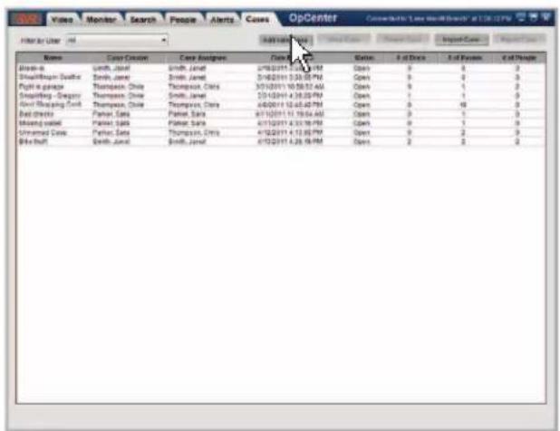
-
Fill out the fields under the Case Summary tab:
-
Case ID: A case ID will be autogenerated for you based on the present date. However, this field may be edited if desired.
• Case Name: Type a name for the case.
• Case Description: If desired, type a summary description for the case. - Assignee: Will be set to the current user account by default. To assign the case to another user, click the link and select the user name from the dropdown list.
-
Private Case: A case marked as a [ ]Private Case will only be visible to the creator and the assignee.
• Status: When creating a new case, the case status will be Open. -
When you are finished editing the details of the new case:
• To create the new case, click Save.
• To clear the form without saving your changes, click Undo Changes.
- To return to the case list, click Return to Cases.

From an Event or Person Card
- Select an event or person card of interest in the Monitor, Search, or People panels.
- In the event editor or person editor, click the Cases tab.
- Click Add Event to New Case (or Add Person to New Case).
-
Fill out the details of the new case:
-
Case ID: A case ID will be autogenerated for you based on the present date. However, this field may be edited if desired.
• Case Name: Type a name for the case.
• Case Description: If desired, type a summary description for the case. - Assignee: By default, the assignee be set to the current user account. To assign the case to another user, click the link and select the user name from the dropdown list.
-
Private Case: A case marked as a [] Private Case will only be visible to the creator and the assignee.
• Status: When creating a new case, the case status will be Open. -
Click Save to save the new case. The event or person card will be added to the case as the first piece of evidence.

2.3 Editing a Case
- Click the Cases tab to go to the Cases panel.
- Select the case of interest from the list of cases.
- Click View Case.
- Edit the fields under the Case Summary tab as desired (see section 2.2 for a description of each setting).
- When you are finished editing the case
• To save your changes, click Save.
• To clear the form without saving your changes, click Undo Changes.
- To return to the case list, click Return to Cases.

2.4 Deleting a Case
- Click the Cases tab to go to the Cases panel.
- Select the case to be deleted from the list of cases.
- Click Delete Case.
- In the Confirm Delete pop-up window, click Yes to permanently delete the case.
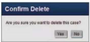
3. BUILDING A CASE
3.1 Adding Events to a Case
Events can be added to a case from the Monitor panel or from the Search panel search results screen with the following steps:
Adding a Single Event Card
- Select the event card(s) of interest.
- In the event editor, click the Cases tab.
- Select an existing case from the list and click Add Event to Case.
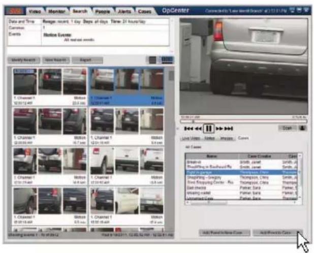
Adding Multiple Events at Once
- Hold the CTRL key and click event cards to select multiple events.
- Right-click one of the selected events and select Add Events to Case from the menu.
- In the Cases tab of the event editor, select an existing case from the list and click Add Events to Case.

3.2 Adding a Person to a Case
People can be added to a case from the People panel with the following steps:
- From the People panel, select a person card.
- Select the Cases tab from the person editor.
- Select a case from the list and click Add Person to Case.
- Click Save.
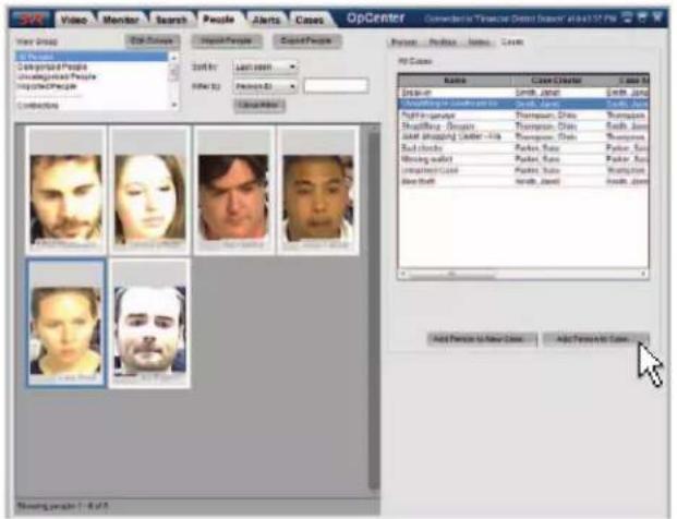
3.3 Removing Evidence from a Case

Note
Closed cases cannot be edited. To remove evidence from a closed case, first re-open the case, then remove the event or person card with the steps in this section.
Use the following steps to remove events or people from a case:
- From the case editing screen, click the Events or People tab.
- Right-click the event or person card to be removed and select Remove from Case.
- To return to the main view of the Cases panel, click Return to Cases.
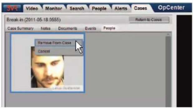
4. ADDING SUPPORTING DOCUMENTS AND NOTES TO A CASE
4.1 Adding a Document to a Case
- Click the Cases tab to go to the Cases panel.
- Select the case of interest from the list of cases.
-
Click View Case.
-
Click the Documents tab.
-
Click Upload.

Details
You may upload any kind of file to the Documents tab, not just text documents. However, the file size must be less than 10 MB.
-
In the Choose Document File window, select the file to upload to the case.
-
Click OK.

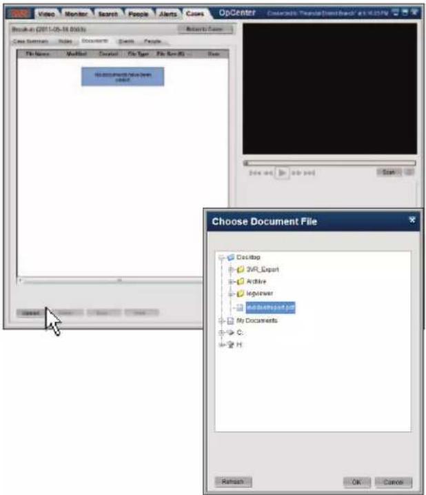
The file will appear in the Documents tab of the case editor.
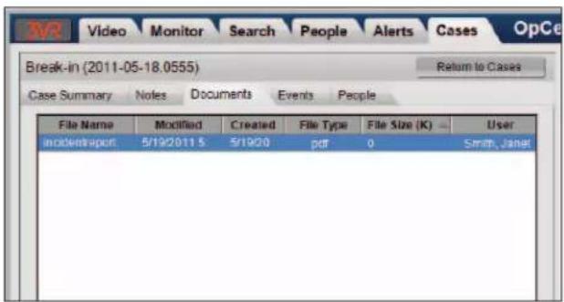
4.2 Working with Documents
Opening a Document
Use the following steps to download and view a file that has been uploaded to a case:
- In the Documents tab, select the file to open.
- Click View.
- The file will open in the application on your computer that has been associated with the file type.
For example, if the document is a .txt file, clicking View will open the file in Windows Notepad or another text editor.
Saving a Document
Use the following steps to save a file from the Documents tab to your computer:
- In the Documents tab, select the file to save.
- Click Save.
- In the Choose Folder dialog, select the directory or drive where you wish to save the document.
- Click Save.

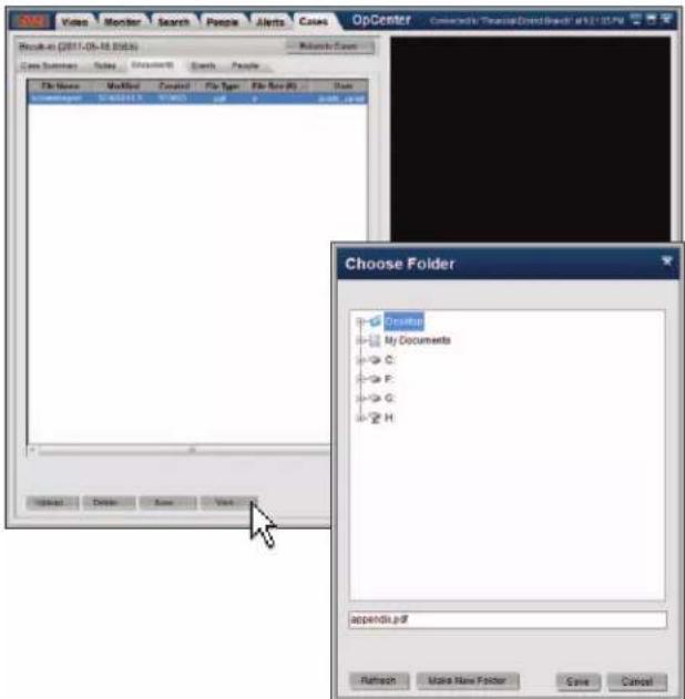
Removing a Document
Use the following steps to remove a file that has been added to a case:
- In the Documents tab, select the file to delete.
- Click Delete.
- In the pop-up window, click Yes to confirm the file should be removed from the case.

4.3 Adding Notes to a Case

Important
Once saved to a case, notes cannot be deleted.
- In the Cases panel, select a case from the list of cases
- Click View Case.
- In the case editing screen, click the Notes tab.
- Click Add a Note.
- Select a label for your note from the Label dropdown menu.

Reference
See Chapter 10: Notes for more information about creating notes and defining note labels.
-
Type the text of the note in the text box.
-
Click Save
The note will be added to the Notes tab of the case editor..

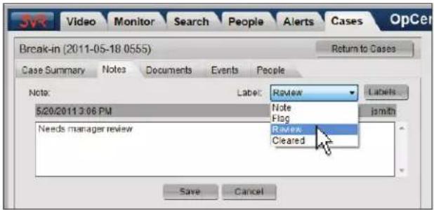

5. EXPORTING A CASE
Exporting a case will convert the case summary, evidence, and supporting documents to a file that may be viewed in web browser (Mozilla Firefox, Internet Explorer, Chrome, or Safari). This allows the details of the investigation to be easily shared with law enforcement, management, or other interested parties.
Use the following steps to export a case from 3VR OpCenter:
- Click the Cases tab to go to the Cases panel.
- Select the case to export.
- Click Export Case.
- Click the dropdown arrow next to Location to select the directory or drive where you wish to save the exported case.
- To create a new folder for the exported case, check []Create new subfolder and enter a folder name.
- Check [ ] Include event details in images to embed details about the source event in images exported with the case.
- Click the Export button.
- When the export is complete, click the Close button.
Export Event


Reference
See Chapter 9: Exported Evidence for more information about viewing exported cases.
CHAPTER 7
People Panel
- GETTING STARTED WITH THE PEOPLE PANEL 102
- WORKING WITH FACE EVENTS 103
2.1 Creating a New Person from a Face Event 103
2.2 Matching a Face Event to an Existing Person 103 - FILTERING AND SORTING PERSON CARDS 104
3.1 Filtering People by Group Membership 104
3.2 Sorting People Chronologically 105
3.3 Filtering People by Name, ID, Gender, and Other Custom Properties 105 - PEOPLE GROUPS 106
4.1 Creating a New Group 106
4.2 Editing People Groups 107
4.3 Deleting People Groups 107 - VIEWING AND EDITING PERSON DETAILS 108
- WORKING WITH PERSON PROFILES 108
6.1 Viewing Profiles Matched to a Person Card 108
6.2 Changing the Display Profile 109
6.3 Unmatching a Profile from a Person Card 109
6.4 Person Profile Images 110 - MERGING TWO PERSON CARDS 111
- EXPORTING PEOPLE 112
8.1 Exporting People 112
8.2 Enterprise OpCenter | Exporting People to Another Appliance 113
1. GETTING STARTED WITH THE PEOPLE PANEL

Licensed Feature
The People panel will not be useful to customers without facial surveillance enabled and configured on one or more cameras. Enabling face requires the system be licensed for the VIP Facial Surveillance analytic. Please contact 3VR Sales or your 3VR reseller for more information.
When a face event in the Monitor or Search panel features someone you want to keep track of, you can enter details about the person in the Person tab of the event editor. After clicking Save, a person card will be created from the face event. You can view all person cards that have been created on the appliance in the OpCenter People panel.
Use the following steps to create a new person from a face event and then view that person in the People panel:
To create a new person from a face event:
- Select the face event of interest.
- In the event editor, click the Person tab.
- Fill out the fields under ( )Edit for the new person.
- Click Save to create the new person.
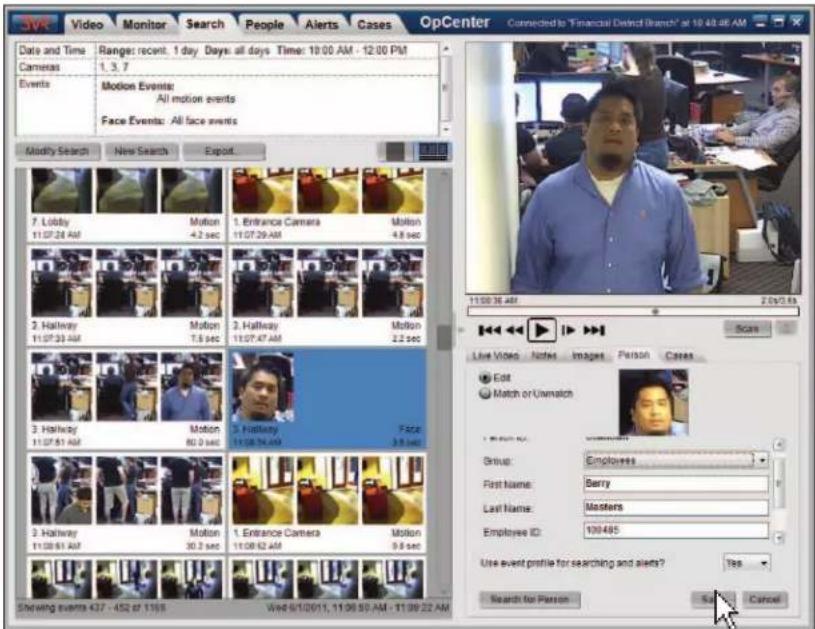
To view the details of an existing person in the People panel:
- Click the People tab to go to the People panel.
- Select the person card of interest.
Details about the person will be displayed in the Person tab of the person editor.

2. WORKING WITH FACE EVENTS
2.1 Creating a New Person from a Face Event
To create a new person from a face event:
- Select the face event of interest.
- In the event editor, click the Person tab.
- To assign the person to a group, open the Group dropdown menu and click a group name.
-
Edit the following person properties as desired:
-
First Name
- Last Name
- Employee ID
Gender - Hair Color
• Any custom fields that have been created for face events.

Reference
See the document Managing Custom Fields on the 3VR VIP Appliance for more information on defining and using custom fields.

- Click Save to create the new person.
2.2 Matching a Face Event to an Existing Person
Use the following steps to match a face event to an existing person. The face event will added to the person card as a profile.
- Select the face event of interest.
- In the event editor, click the Person tab.
- Select ( )Match or Unmatch.
-
Locate the person to match with the face event in one of the following ways:
-
Select a radio button beside Show People to select which list of people to display, ( )Named or ( )All.
• To filter profiles based on last name or Person ID, select Name/ID from the drop-
down menu. Type part or all of the last name or ID number for the profile you are looking for and press the Enter key.
- To filter profiles by group, select Group from the dropdown menu and select the group name from the second dropdown menu.
- Select the person in the face event from the list.
- Click the Match button to add the face event to the selected person card as a profile.

3. FILTERING AND SORTING PERSON CARDS
By default, the People panel will display all people that have been created in the system. Users may filter and sort person cards using the controls at the top of the People panel.
3.1 Filtering People by Group Membership
Groups provide a way of categorizing people who have been created in the system.
A list with all people groups will be displayed in the upper-left corner of the People panel.

Note
There are seven default people groups in OpCenter: Contractors, Employees, Maintenance, Suspicious People, Unknown People, Vendors, and Visitors. To create your own people groups, see section 4.1.
Select a group name from this list to filter the person cards by group membership. Only the people that have been assigned to the selected group will be displayed.
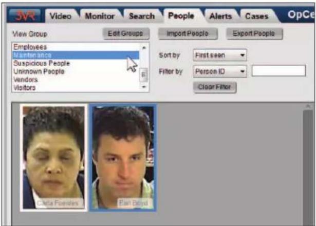
You can also filter people by one of the general categories at the top of the group list:
- All People
The default view of the People panel. Displays all people that have been created on the appliance.
• Categorized People
Displays only people that have been assigned a group membership.
• Uncategorized People
Displays only people that have not been assigned a group membership.
- Imported People
Displays only people that were imported into the system.
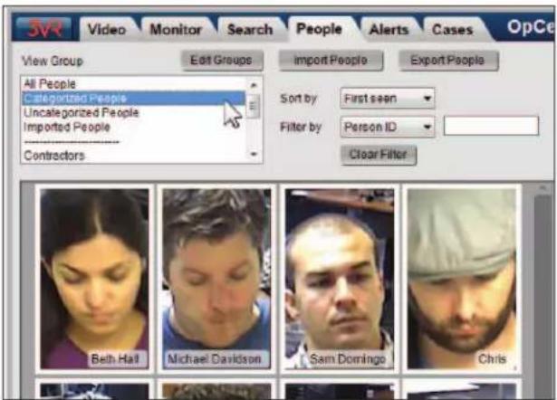

Reference
See section 5 of this chapter for information on exporting and importing people.
After selecting a group or category, person cards for all members of the selected group will be displayed. If a group has more members than can be displayed on the screen at once, use the scroll bar to scroll through all group members.
3.2 Sorting People Chronologically
Use the Sort by dropdown menu at the top of the People panel to change the ordering of person cards.
- To display person cards in the order of their most recent appearance in the system, select Last seen from the Sort by dropdown menu. Person cards matched to the most recent face events are displayed first.
- To display person cards in the order of their oldest appearance in the system, select First seen from the Sort by dropdown menu. Person cards matched to the oldest face events are displayed first.
- To display person cards in alphabetical order by last name, select Last name from the Sort by dropdown menu. Person cards without assigned last names will be displayed first, followed by people with last names in alphabetical order.

3.3 Filtering People by Name, ID, Gender, and Other Custom Properties
Use the Filter by control at the top of the People panel to filter people by manually edited properties such as name, employee ID, gender, etc.
For example, to filter by first name:
- Select First name from the Filter by dropdown menu.
- Type one or more character(s) to search for in the text box.
- Press the Enter key.
- The People panel will update to display only person cards with first names matching the filter character(s).


Notes
1) The options listed in the Filter by menu will vary depending on the custom fields that have been created for face events. See the document Managing Custom Fields for more information on defining and using custom fields.
2) Only properties that have been manually edited on one or more person cards will return meaningful results when filtering people.
4. PEOPLE GROUPS
4.1 Creating a New Group
Use the following steps to create a new people group.
- Click the People tab to go to the People panel.
-
Click Edit Groups.
-
Click Add New Group.
-
Type the Name of the new group.
This name will appear on person cards as well as on any face events matched to any profiles in this group.
- Enter a brief Description of the group.
-
Click Save to create the new group.
-
The new group will appear in the list of groups.


4.2 Editing People Groups
Use the following steps to modify the name or description of a people group.
- Click the People tab to go to the People panel.
- Click Edit Groups.
- Select the name of the group to edit.
- Click Edit.
You will be returned to the Editing Groups screen (see section 3.1 for reference image). Modify the group name and/or description as desired, then click Save.
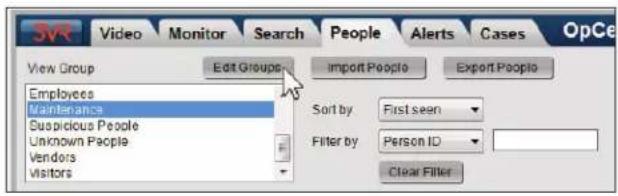

4.3 Deleting People Groups
Use the following steps to delete a people group.
- Click the People tab to go to the People panel.
- Click Edit Groups.
- Select the name of the group to delete.
- Click Delete.

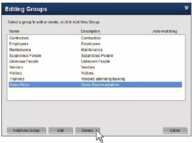

Note
Groups with members cannot be deleted. You must first move each group member to a different group (or mark them as uncategorized) by individually editing each person card. You may delete the group once all members have been moved.
5. VIEWING AND EDITING PERSON DETAILS
- Click the People tab to go to the People panel.
- Select the person card of interest.
-
Details about the person will be displayed in the Person tab of the person editor:
-
Person ID
- First Name
-
Last Name
• Custom Properties (Employee ID, Gender, Hair Color, etc.) -
Click the remaining tabs in the person editor to view and/or edit the following items:
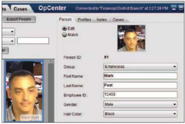
- Profiles: The Profiles tab contains face events that have been matched to the person. Each individual face event is considered a "profile" of the person.

More
See section 6 of this chapter for information about person profiles.
Notes: Any notes added to the person will be displayed by selecting the Notes tab of the person editor. Or, to add a note to the person, click the Add a Note button in this tab.

Reference
See Chapter 10: Notes for more information about notes and note labels.
- Cases: You can add the person to a case from the Cases tab of the person editor.

Reference
See Chapter 6: Cases Panel for more information about cases.
6. WORKING WITH PERSON PROFILES
6.1 Viewing Profiles Matched to a Person Card
The Profiles tab of the person editor contains face events that have been matched to a person. Each face event is called a "profile" of the person. Matching high-quality face event cards to people helps the system improve its ability to recognize that person over time.
- Click the People tab to go to the People panel.
- Select the person card of interest.
- In the person editor, click the Profiles tab. All profiles that have been matched to the person will be displayed.
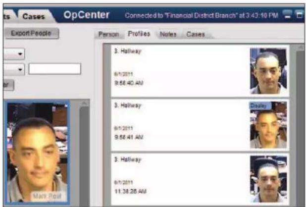
6.2 Changing the Display Profile
Although a single person card may have multiple matched profiles appearing in the Profiles tab, one profile must always be identified as the primary profile for the person. This profile is called the Display profile. The best image from the Display profile is used to identify the person wherever they appear in OpCenter.
By default, the first face event used to create a person is used as the Display profile. However, you may promote another profile to be the Display profile with the following steps:
- Click the People tab to go to the People panel.
- Select the person card of interest.
- In the person editor, click the Profiles tab. All profiles that have been matched to the person will be displayed.
- Select the profile to promote and click Use as Display Image.
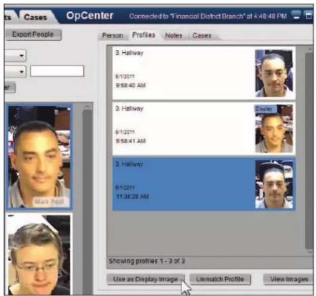
6.3 Unmatching a Profile from a Person Card
A profile should be unmatched from a person card for one of the following reasons:
- The profile was matched to the person card in error (it is not the same person)
-
The profile was matched correctly, but the profile is not representative of the person's face due to image quality or another reason (bad lighting, extreme angle, glasses present that are not normally worn, etc.)
-
Click the People tab to go to the People panel.
- Select the person card with a mismatched profile.
- In the person editor, click the Profiles tab.
- Select the incorrect profile.
- Click Unmatch Profile.
- In the Unmatch Profiles dialog, specify what to do with the profile that is being unmatched:
- For low-quality profiles, select ( )Keep selected profile on this person, but do not use for future searches and alerts. The profile will still be associated with the person card, but it will not appear in the Profiles tab and its images will not be used for face searching.

Note
This option is not available for profiles created by imported images.
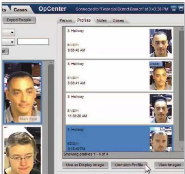

- For incorrectly matched profiles that should be turned into a separate person card, select ( )Create a new person from the profile.
The person will be created and placed in the Uncategorized group.
For incorrectly matched profiles you do not wish to save, select ( )Unmatch without creating a new person.
- Click Unmatch to unmatch the profile.
6.4 Person Profile Images
Viewing Profile Images
Each profile matched to a person card contains up to three person profile images, thumbnail images of the person's face auto-generated by the source face event.
Use the following steps to view the images from a person profile:
- Click the People tab to go to the People panel.
- Select the person card of interest.
- In the person editor, click the Profiles tab. All profiles that have been matched to the person will be displayed.
- Select a profile and click View Images.
A dialog will appear with all of the thumbnail images for the selected profile.

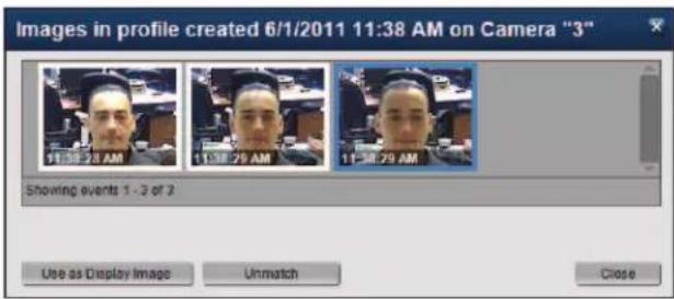
Changing the Display Image for the Profile
Just as one profile is always defined as the Display profile for a person card (see section 6.2), one of the profile images is used as the Display image for the profile. The Display image is used as the reference image for the profile in the Profiles tab.
By default, the middle thumbnail from the face event is used as the Display image for the profile. To use one of the other profile images as the Display image, select the image thumbnail and click Use as Display Image.

Unmatching a Profile Image from a Profile
If one of the auto-generated profile images is of low-quality or is not an image of the selected person, you should unmatch the profile image from the person profile. To unmatch a profile image:
- Select the image thumbnail.
- Click Unmatch.
- In the Unmatch Profiles dialog, specify what to do with the profile that is being unmatched:
- For incorrectly matched profiles that should be turned into a separate person card, select ( )Create a new person from the profile.
The person will be created and placed in the Uncategorized group.
- For incorrectly matched profiles you do not wish to save, select ( )Unmatch without creating a new person.
- Click Unmatch to unmatch the image.

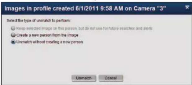
7. MERGING TWO PERSON CARDS
Use the following steps to merge two person cards that have been created for the same person. When people are matched together, the result will be a single person card containing profiles (matched face events) from both of the merged cards.
Please note that the person details (first name, last name, ID, etc.) will only be kept for the person card selected first.
- Click the People tab to go to the People panel.
- Select the person card with person details that should be retained.
- In the Person tab of the person editor, select ( )Match.
- Click the name or image of the profile you wish to merge with the selected person.

More
You can filter the list of people under ( )Match in a number of ways. See section 2 of this chapter for details.
- Click the Match button to merge the selected people.
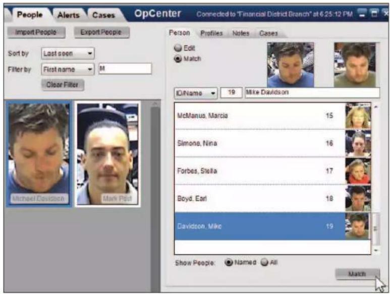
8. EXPORTING PEOPLE
8.1 Exporting People
Exporting a person will convert the person details and profile images to a file that may be viewed in web browser (Internet Explorer, Firefox, Chrome, or Safari). This allows information about the person to be easily shared with law enforcement, management, or other interested parties.
Use the following steps to export people to XML:
- Click the People tab to go to the People panel.
- Select the person card to export, or hold the CTRL key and click person cards to select multiple events.
-
Click Export People.
-
In the Exporting People dialog, select ( )Export to Folder.
- Click the dropdown arrow next to Location to select the directory or drive where you wish to save exported events.
- To create a new folder for exported events, check [ ]Create new subfolder and enter a folder name
- If you are exporting people for import into the 3VR CrimeDex database, check [ ] Include ZIP file.

More
To learn more about 3VR CrimeDex, an online community where fraud, loss prevention, and law enforcement professionals collaborate to solve crimes faster, visit www.crimedex.com.
- Click the Export button.
- When exporting has completed, click Close.

Reference
See Chapter 9: Exported Evidence for more information about viewing exported events.


8.2 Enterprise OpCenter | Exporting People to Another Appliance
In addition to exporting to XML, Enterprise OpCenter allows exporting of people between appliances on the Enterprise.
Follow these steps to share people that have been created on one system with other appliances on the Enterprise:
- Click the People tab to go to the People panel.
- Select the person card to export, or hold the CTRL key and click person cards to select multiple events.
-
Click Export People.
-
In the Exporting People dialog, select ( )Export people directly to selected 3VR systems.
-
In the Export To box, check the box next to each appliance to include in the export.
To share the selected people with every system on the Enterprise, click Select All.
To export any alerts that have been created for the selected people, check the box next to [ ]Export Alerts.
-
Click the Export button.
-
A confirmation dialog will appear. Click Yes to proceed with the export.
When the people sharing process is complete, the Status field will display a summary of the export.
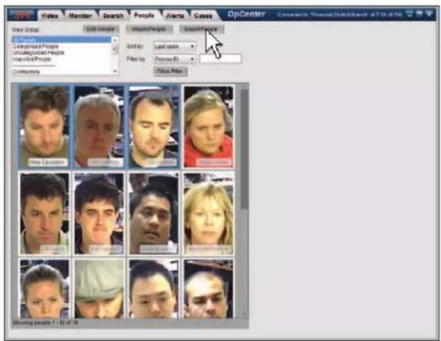

CHAPTER 8
Notes
- ABOUT NOTES 116
1.1 Notes Overview 116
1.2 Viewing a Note 116 - ADDING A NOTE 117
2.1 Adding a Note 117
2.4 Re-Labeling a Note 118 - MANAGING NOTE LABELS 119
3.1 Creating a Custom Note Label
3.2 Editing or Deleting a Note Label 119
119
1. ABOUT NOTES
1.1 Notes Overview
The Notes feature of OpCenter allows users to add plain text notes to events, people, and cases of interest.
To view the notes that have been added to an event card, or to add a new note, open the event in the event editor and click the Notes tab (the event editor appears in the Monitor panel, Search panel results screen, and the Cases panel). Notes can also be added to a selected person card in the People panel, and to a case in the Cases panel.
Notes on events may be categorized through the use of note labels; for example, you might add a note to an event card with the Flag label to mark the card for manager attention.
1.2 Viewing a Note
To view the notes attached to an event:
-
Select an event card with a note. Note events are marked with a blue stripe and the note label.
-
In the event editor, click the Notes tab to display all notes for that event, including the date, time, and author of each message.
A note may be labeled with Note, Flag, Review, Cleared or a custom label created by a user with administrative privileges.

To view the notes attached to a person card:
-
Select a person card with a note.
-
In the person editor, click the Notes tab to display all notes for that person, including the date, time, and author of each message.

To view the notes attached to a case:
-
Select a case with a note.
-
Click View Case.
-
In the case editor, click the Notes tab to display all notes for that case, including the date, time, and author of each message.

2. ADDING A NOTE

Warning
Once a note has been saved to an event, person, or case, it cannot be edited or deleted.
2.1 Adding a Note
- Select an event card, a person card, or a case.
- Click the Notes tab.
- Click the Add a Note button.
- If you are adding a to an event, select a label for the note from the Label dropdown menu. This label will be displayed in the top right corner of the event card to indicate the type of note attached.

Note
See section 3 of this chapter for information on creating custom note labels.

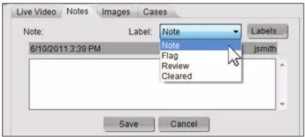
- Type your note in the text box.
-
Click the Save button.
-
When you click Save, the system will automatically add the date, time, and author to the note.
In addition, the event card will be stamped with the note label.


2.4 Re-Labeling a Note
Note labels can be used to distinguish between different types of notes. The 3VR system comes with four predefined note labels: Note, Flag, Review, and Cleared. When adding a note to an event, the label Note will be used by default unless a different label is selected.
While the text of a note cannot be edited after it is saved to the event, you can change the label affixed to the event card with the following steps:
- Select an event card with a note.
- In the Notes tab of the event editor, click the dropdown arrow next to Label to display the four default labels, as well as any custom labels created on your system.
- Select a different label for the event from the list.
The event card will instantly be updated with the new note label.
If desired, you may also add a new note to indicate why note label was changed.
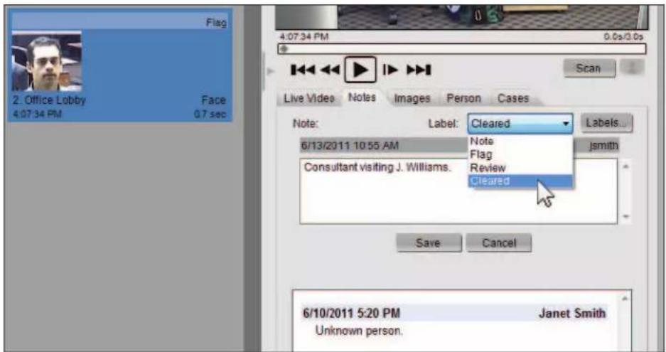
3. MANAGING NOTE LABELS
3.1 Creating a Custom Note Label
To create a new note label:
- From the Notes tab of the event editor, click the Add a Note button.
- Click the Labels button.
- Type a new label and click the Add button.
This new label will be added to the list of labels and will be available in the Label dropdown menu in the Notes tab.
- Click the Close button. You can now use this label when adding a note to an event.
3.2 Editing or Deleting a Note Label
To edit or delete an existing label:
- From the Notes tab of the event editor, click the Add a Note button.
- Click the Labels button.
- Select a note label from the list.
- To edit the note label, click Edit. Modify the label in the text box and click Save.
• To delete the note label, click Delete.

Note
Labels that are in use cannot be deleted. Before deleting a label, you must manually re-assign each note currently using the label to a different label. Perform a search for [ ]Events With Notes in the Search panel to identify notes that must be relabeled.
- When you are finished editing note labels click Close.
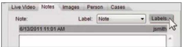

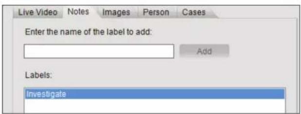


CHAPTER 9
Viewing Exported Evidence
- VIEWING EXPORTED EVENTS, PEOPLE, AND CASES 122
- VIEWING EXPORTED VIDEO 123
2.1 Viewing Exported Video in Evidence Viewer 123
2.2 Viewing Exported Video in a Supported Media Player 123 - EVIDENCE VIEWER OVERVIEW 124
3.1 About Evidence Viewer 124
3.2 Obtaining Evidence Viewer 124 - OPENING EXPORTED VIDEO IN EVIDENCE VIEWER 124
4.1 Automatically Load Video from Export Folder 124
4.2 Manually Select Export Folder 125 - REVIEWING VIDEO IN EVIDENCE VIEWER 126
5.1 Controlling Video Playback 126
5.2 Saving a Single Frame as an Image 127 - CUSTOMIZING EVIDENCE VIEWER 127
6.1 Changing the Number and Size of Video Players 127
6.2 Adding and Removing Cameras 128
6.3 Camera Overlays 129
6.4 Showing or Hiding the Video Timeline and Camera Tree 129 - DIGITAL ZOOM 130
7.1 Entering Zoom Mode 130
7.2 Shifting the Zoomed Region 131
7.3 Exiting Zoom Mode 131 - VALIDATING EXPORTED EVIDENCE 131
8.1 About Evidence Validation 131
8.2 Validating Exported Events, People, and Cases in 3VR OpCenter 131
8.3 Validating Exported Video in 3VR Evidence Viewer 133
1. VIEWING EXPORTED EVENTS, PEOPLE, AND CASES
Events, people, and cases exported from OpCenter are converted into an XML file with associated resources that can be viewed in a supported web browser (Internet Explorer, Firefox, Chrome, or Safari).
Use the following steps to view exported surveillance in a web browser:
-
Open the folder containing the exported surveillance.
-
The export folder will have the following contents:
• An XML file:
3VR_events.xml,
3VR_people.xml,
or 3VR_cases.xml
• A readme file, readme.html
• One or more folders containing video clips and/or images.
- To view the exported surveillance, right-click the XML file and select Open with > from the menu, then select your web browser.
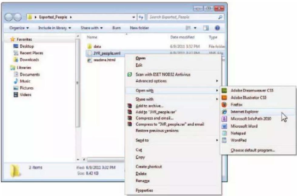
- The exported surveillance will be displayed in a storyboard format in the web browser. To play back the video clip(s), click the Watch video link below each clip.

Note
For more information, see the readme.html file included in the export folder.

2. VIEWING EXPORTED VIDEO
Video exported from the OpCenter Video panel can be viewed in one of two ways:
• In 3VR Evidence Viewer, if the application was included with the export or has been downloaded separately.
• In QuickTime or Windows Media Player, if Evidence Viewer is unavailable.
2.1 Viewing Exported Video in Evidence Viewer
3VR Evidence Viewer is a powerful tool that allows simultaneous viewing of one or more cameras of exported video. Evidence Viewer replicates the functionality of the 3VR OpCenter Video panel for evidence recipients (e.g., law enforcement, court officials, etc.) without access to the 3VR system.

Reference
See section 3 of this chapter for a user guide for 3VR Evidence Viewer.
2.2 Viewing Exported Video in a Supported Media Player
If Evidence Viewer was not included with the export, exported video clips can be viewed one at a time in one of the supported media players (QuickTime, Windows Media Player*, or VLC).
To view an exported video clip:
- Open the export folder.
- Right-click the video clip of interest and select Open with > QuickTime or Open with > Windows Media Player.
pen the export folder.
The selected video clip will open in your media player of choice.
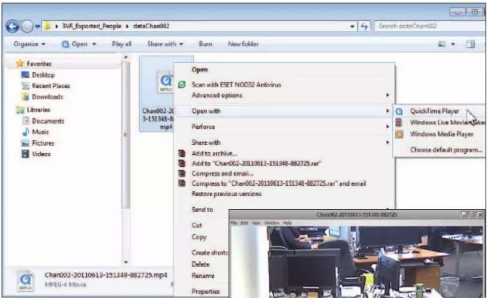

natural_image
Office workspace with desks, computers, and office equipment (no visible text or symbols)
Note
Playing back video exported from OpCenter in Windows Media Player requires the 3VR Windows Media Player codec, available for download at www.3VR.com
3. EVIDENCE VIEWER OVERVIEW
3.1 About Evidence Viewer
3VR Evidence Viewer is a powerful tool that allows you to simultaneously view one or more cameras of video exported from the 3VR OpCenter Video panel without requiring the purchase of additional software. 3VR Evidence Viewer is ideal for sharing exported video with law enforcement or other investigators.
With 3VR Evidence Viewer you can:
• Simultaneously view up to 36 cameras of exported video
- Select which cameras to display in the current view
- Scan video using a video timeline
- Automatically verify the integrity of the video being viewed, displaying a warning if the exported video or associated information has been tampered with or modified in any way.
Evidence Viewer is fully supported in Windows XP, Windows Vista, and Windows 7.
3.2 Obtaining Evidence Viewer
Evidence Viewer is installed with 3VR OpCenter. If you are connecting to a 3VR appliance over a network using OpCenter, you will have the option to include Evidence Viewer with exported video files. The Evidence Viewer application .exe will be located inside the export folder.
However, if you will be emailing the exported video or transferring the export folder via a slow network connection, it is recommended that you do not include the 20MB Evidence Viewer application in the exported folder. Instead, advise the person receiving the exported video to download Evidence Viewer from www.3VR.com (click Services & Support > FAQ).
Instructions for obtaining 3VR Evidence Viewer are included with every video export.
4. OPENING EXPORTED VIDEO IN EVIDENCE VIEWER
There are two ways to load video in Evidence Viewer:
4.1 Automatically Load Video from Export Folder
To automatically load video when Evidence Viewer is launched, drag the application (3VREvidenceViewer.exe) into the exported video folder. If the Evidence Viewer application was included in the exported video folder, there is no need to move the application — simply double-click the Evidence Viewer icon and exported video in the same folder will load automatically.
- Open the folder containing the exported video.
- Double-click 3VREvidenceViewer.exe to launch the application.

- When Evidence Viewer loads, it will automatically locate and play back 3VR video files located in the same folder as the application.
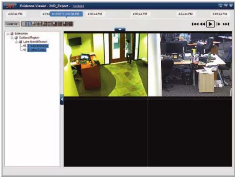
4.2 Manually Select Export Folder
To use Evidence Viewer for viewing video from multiple exported folders, you may wish to keep the Evidence Viewer application in a single location. For example, you may wish to save Evidence Viewer in the Program Files directory (usually C:\Program Files\3VR) if it is not already there, and place a shortcut to Evidence Viewer in your Start menu.
However, if Evidence Viewer is not located in the exported video folder, when you double-click the Evidence Viewer icon, you will be prompted to select the location of the exported video.
- Launch Evidence Viewer.
- In the Location of Video Files dialog, browse to location of the folder containing the exported video. Select the folder name.
- Click OK.
Evidence Viewer will load the 3VR video files located in the selected folder.
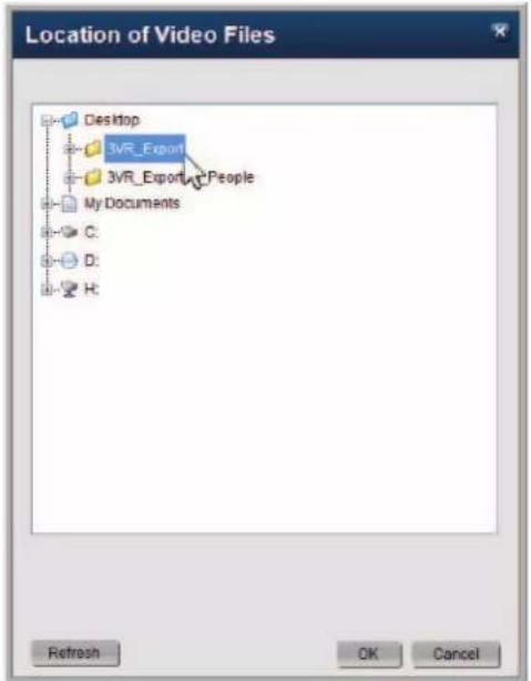
5. REVIEWING VIDEO IN EVIDENCE VIEWER
5.1 Controlling Video Playback
You can control video play back in Evidence Viewer using either the video timeline or the video playback controls.
Scanning with the Timeline
The timeline control across the top of the Evidence Viewer application spans the duration of the exported video. The time when the video you are viewing took place is overlaid on the timeline in the scrolling time slider.
Click and drag the time slider to scan forward or backward to a different point in time. Use the time points above the timeline as guides for selecting a time. When you release the mouse button, video playback will resume at the selected time.

Using the Video Playback Controls
Use the video playback controls below the timeline to control the playback of stored video in the following ways:

Pause: Pauses video playback.

Play: Restarts video playback.

Fast-forward: Fast-forwards through video. Clicking the fast-forward button multiple times increases the fast-forward speed (.5x, 2x, 4x, 8x, or 16x).

Rewind: Rewinds through video. Clicking the rewind button multiple times increases the rewind speed (.5x, 1x, 2x, 4x, 8x, or 16x).

Forward 15 minutes: Jumps playback 15 minutes forward on the timeline.

Back 15 minutes: Jumps playback 15 minutes back on the timeline.

Frame forward: When video is paused, clicking this button skips ahead to the next frame.
5.2 Saving a Single Frame as an Image
Use the following steps to save a single frame from stored video to your computer or an external drive:
- Click the pause button to pause playback on the frame of interest.
- Right-click the paused video player and select Save Image.
- Select the directory or drive where you wish to save the image file.
- Edit the file name if desired.
- Click the Save button to save the image.

6. CUSTOMIZING EVIDENCE VIEWER
6.1 Changing the Number and Size of Video Players
The layout selector at the top of the Evidence Viewer controls the number and arrangement of video players.
Select a different layout button to increase or decrease the number and positioning of players as desired.

Up to 36 cameras can be displayed at a time in Evidence Viewer.

Tip
To re-arrange the selected cameras, click and drag the mouse from one video player to another video player. When you release the mouse button, the cameras will switch places.

6.2 Adding and Removing Cameras
Which cameras are displayed in the Evidence Viewer video grid can be specified in a number of ways.
Adding Cameras With Drag and Drop
Drag and drop a camera name from the camera tree to a video player to view the camera in the player.
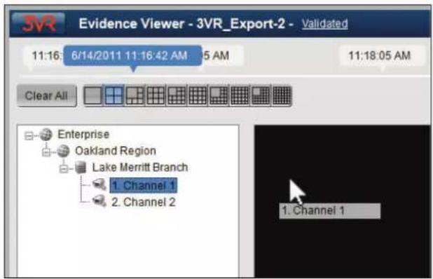
Adding Cameras With Right-Click Menus
Cameras may also be selected using right-click menu options.
- To change the camera displayed in a specific video player, right-click the player, select Add>, then click Add "[Camera Name]".
- To add a camera to the first available video player, right-click the camera name in the camera tree and select Add "[Camera Name]".

Removing Cameras
There are several ways to stop streaming a camera that is currently playing in Evidence Viewer:
- To remove a specific camera, right-click the video player and select Remove "[Camera Name]".
• To remove all currently selected cameras:
Right-click anywhere in the camera tree or video player grid and select Clear All.
Another way to clear all selected cameras is to click the Clear All button, located to the left of the layout selector.
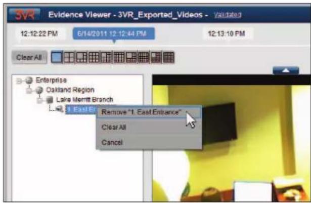
6.3 Camera Overlays
If you would like to display information about the camera on top of each video player, change the camera overlays with the following steps:
- Right-click anywhere in the video grid.
-
Select Overlays >, then choose an overlay from the sub-menu. The current overlay options are:
-
Camera Name
• Camera Number and Name
• Appliance Name, Camera Number, and Name - No Overlay

- By default, camera overlays are placed in the top-left corner of each video player. If desired, you can re-position the overlay by clicking and dragging the overlay box.
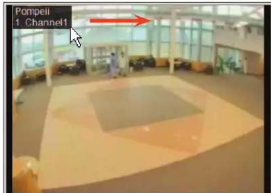
Start
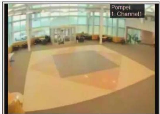
End
6.4 Showing or Hiding the Video Timeline and Camera Tree
Both the camera tree and the video timeline may be hidden from view.
- Click the left-facing arrow to the right of the camera tree to hide the tree.
- Click the upward-facing arrow below the video timeline to hide the timeline.
To re-display the timeline and/or camera tree, click the arrows again.

natural_image
Office workspace with employees at desks and computers, no visible text or symbols on equipment7. DIGITAL ZOOM
3VR Evidence Viewer features the ability to zoom in on a region of interest in the camera video feed. This "digital zoom" feature adds PTZ-like functionality to fixed analog and IP cameras.
7.1 Entering Zoom Mode
There are two ways enter zoom mode:
Zooming with the Mouse Scroll Wheel

Note
While digital zoom is supported for any non-PTZ camera, cameras with resolutions greater than 1 MP will produce the best results.
- Click the video player to center the zoom, then use your mouse's scroll wheel to zoom in and out.

Start

natural_image
Interior scene with two people seated, one holding a smartphone, in a dimly lit room with blurred background (no visible text or symbols)End
Zooming While Holding the CTRL Key
- While holding down the CTRL key, click and drag the mouse over the video feed to draw a box over the region of interest. Release the mouse button to zoom in on the region.

Start
natural_image
Close-up of a man in formal attire, focused on something with no visible text or symbolsEnd
7.2 Shifting the Zoomed Region
When a video player is in zoom mode, a zoom inset will appear in the bottom-left corner of the video player. The zoom inset contains a white outline representing the current zoom level.
Shift the zoomed region by clicking and dragging the white box in the inset.

natural_image
Interior scene with two people in conversation, one pointing at a small object (no visible text or symbols)Start

natural_image
Interior scene with people in a hallway, no visible text or symbolsEnd
You can also nudge the zoomed region up, down, left, or right using the arrow keys on your keyboard.
7.3 Exiting Zoom Mode
You can exit zoom mode in one of two ways:
• Double-click the video player.
- Press the escape key on your keyboard (Esc).
8. VALIDATING EXPORTED EVIDENCE
8.1 About Evidence Validation
When events and video are exported from the 3VR system, they are digitally watermarked using SHA-1 encryption. This watermark ensures that the exported evidence has not been tampered with, as modifying the file in any way will invalidate the watermark. For example, editing the date of the recorded video in an event xml file, or deleting frames from exported video clips and re-saving the video, will produce an error if the evidence is run through the validation tool.
8.2 Validating Exported Events, People, and Cases in 3VR OpCenter
3VR customers may use OpCenter's validation tool to verify that the contents of a 3VR event export folder have not been tampered with:
- Launch 3VR OpCenter and click the Search tab.
-
Click the Validation tab.
-
Click the dropdown arrow next to File or Folder to open the file browser menu.
- Select the directory where the exported event or case file is located, then click OK.
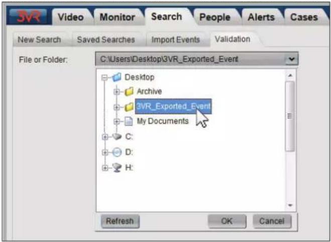
- Click Validate to begin the validation process.

- A message will be displayed indicating the result of the validation process:
- Folder validated with no errors or

• Authentication Failed

- Click Close when you are finished to return to the Search panel.
8.3 Validating Exported Video in 3VR Evidence Viewer
Evidence recipients can validate exported video in 3VR Evidence Viewer:
- Open the folder containing the exported evidence and double-click EvidenceViewer.exe
- 3VR Evidence Viewer will launch and automatically load the exported video contained in the same folder.
- The title bar of the Evidence Viewer application will display Validated for validated video. Click the link to view more information.

If validation fails, you will be shown a Validation Exception(s) error message when the problematic video is opened in Evidence Viewer.
Validation Exception(s)
The XML configuration file does not match the file originally exported from the 3VR appliance (indicating it may have been damaged or edited). The validity of any associated video or data files cannot be established.

CHAPTER 10
Importing
- IMPORTING OVERVIEW 136
- CONFIGURE IMPORT CAMERA ON APPLIANCE 136
- IMPORTING EVENTS 138
3.1 Importing Events from XML 138
3.2 Importing Events from Video 139
3.3 Viewing Imported Events 139 - IMPORTING CASES 141
4.1 Importing Cases from XML 141
4.2 Viewing Imported Cases 141 - IMPORTING PEOPLE 142
5.1 Importing People from XML 142
5.2 Importing People from Images 143
5.3 Importing People from 3VR CrimeDex 147
5.4 Viewing Imported People 148
1. IMPORTING OVERVIEW
This chapter addresses how to import surveillance data (events, cases, video, images, etc.) into a 3VR VIP Appliance. There are two reasons why a user might want to import data:
a. To import data from other sources, such as images or video, that will be used in 3VR applications. For example, you may import a set of image files for use with the 3VR VIP Facial Surveillance analytic.
b. To transfer surveillance exported from one appliance (the source appliance) to another (the destination appliance). This use case is most relevant for customers operating in a non-networked environment — multiple standalone appliances at different locations that are not connected by an Enterprise Appliance.

Notes
1) Original system and camera info may be lost when importing data that was exported from another appliance. 3VR recommends using an Enterprise Appliance to manage cases.
2) For instructions on exporting surveillance from the source appliance, please see the chapter of the 3VR User Manual specific to the type of exported data.
| Topic Chapter | |
| Exporting Video Chapter | 2: Video Panel |
| Exporting Events Chapter | 3: Monitor Panel |
| Exporting Cases Chapter | 4: Cases Panel |
| Exporting People Chapter | 7: People Panel |
2. CONFIGURE IMPORT CAMERA ON APPLIANCE

Important
The steps in this section must be completed by a user account with integrator permissions. Please contact your 3VR reseller for assistance with these steps.
Prior to importing surveillance, the 3VR appliance must have at least one import camera configured for the imported data type (images, video, or XML). Camera configuration is performed in 3VR's system maintenance and administration application, System Manager:
- Launch System Manager.
- In the Configure panel, click the plus sign next to the appliance name to display the list of configuration options.
- Click the plus sign next to Cameras.
- Select an unused camera to designate as the import camera.

If all cameras are currently in use, right-click Cameras and select Add Camera.
• A new camera will appear at the end of the list of cameras.

• Right-click the camera and select Enable Camera.
- On the right-hand side of System Manager, click the link next to Edit Camera Type (the link text will be the current camera type, e.g. Analog, Network, or Unknown).
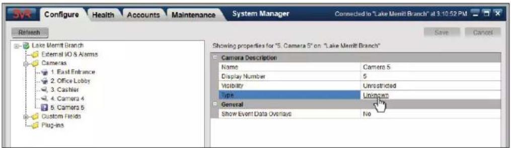
- In the Edit Camera Type dialog, select the camera type appropriate for the imported data:
To import events, people, or cases exported from another appliance, select ( )Imported XML.
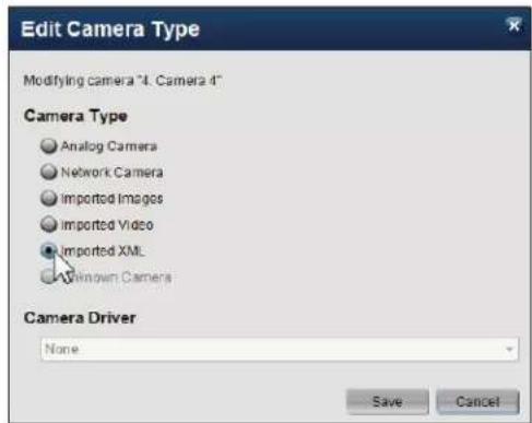
To import images, select ( )Imported Images.
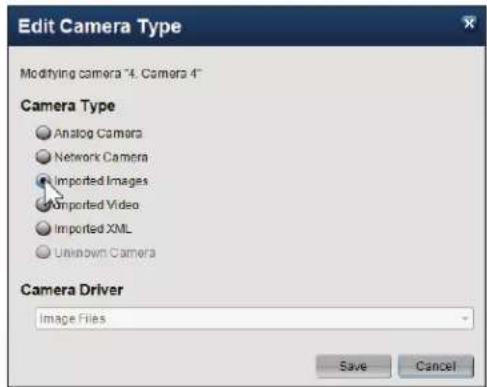
To import video files, select ( )Imported Video.

-
Click Save.
-
Scroll to the top of the settings for the import camera. Edit the Name setting to a name that identifies the camera as an import camera.

- Click Save to save the new camera name.
3. IMPORTING EVENTS
3.1 Importing Events from XML
Use the following steps to import one or more events exported from another 3VR appliance:
- Launch 3VR OpCenter.
- Click the Search tab to go to Search panel.
- Click the Import Events tab at the top of the panel.
- Select ( )XML as the import type.
- Click the dropdown arrow next to XML File Name to open the file browser menu. Navigate to the export folder.
-
Select the 3VR_events.xml file and click OK.
-
Click the Import button to import the selected event(s).
-
After the import is complete, click the Close button.
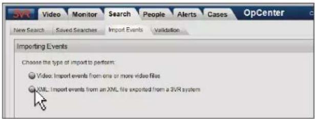

3.2 Importing Events from Video
Use the following steps to import one or more video files as events:
- Launch 3VR OpCenter.
- Click the Search tab to go to Search panel.
- Click the Import Events tab at the top of the panel.
-
Select ( )Video as the import type.
-
Click the dropdown arrow next to Video File or Folder to open the file browser menu. Navigate to the export folder.
-
Select the video file to import (or select a folder to import all video files in the folder) and click OK.

Note
The video import function supports .avi video files only.
- Click the Import button to import the selected video file(s).
- After the import is complete, click the Close button.

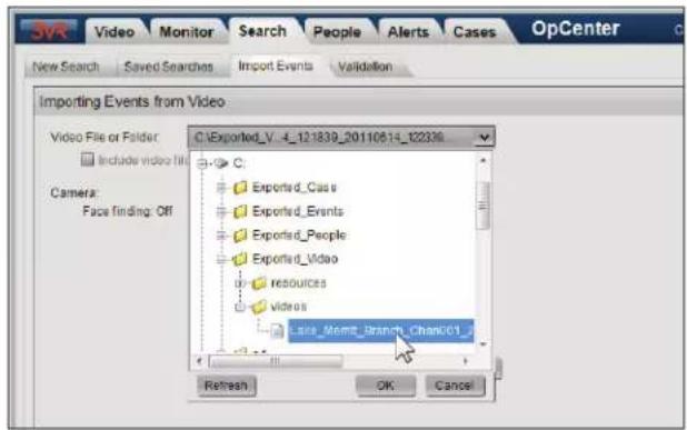

3.3 Viewing Imported Events
Events Imported from XML

Important
Imported events will have their original camera name and number replaced with the camera name and number of the import camera. In addition, the name of the source appliance will be changed to the destination appliance name.
To view events imported from XML, run a search for events on the import camera in the Search panel:
- Click the Search tab to go to the Search panel.
- Under Date Range, select a date and time frame that encompasses the date and time of the imported events. For example, if the events occurred the previous day, select ( )Specify and set the Start and End dates accordingly.
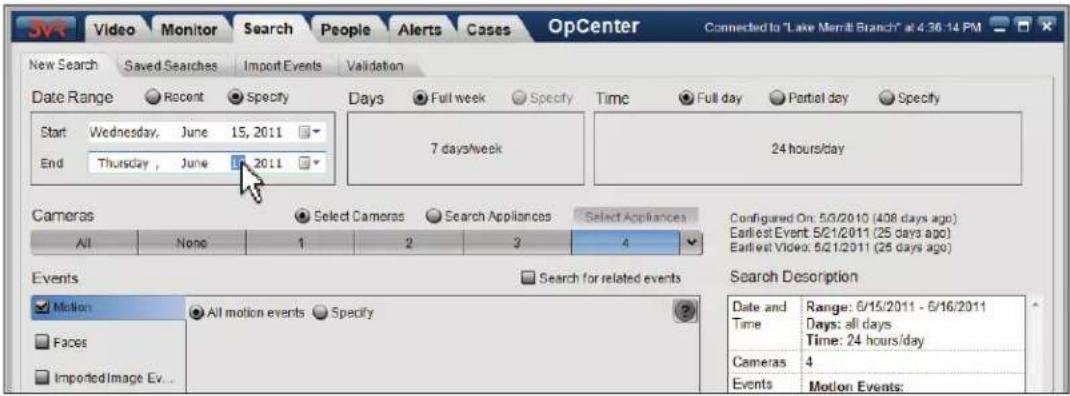
-
Click the camera number of the import camera.
-
Under Event Type, click the event type of the imported events (e.g., motion, face, etc.).
-
Click Search.
Events Imported from Video
Events generated from imported video files will be stored in the database with time stamps starting at the time of importing and extending into the future. This allows events from imported video to be played back in "real time" with respect to other events in the sequence, even if their absolute time is incorrect.
For example, importing an hour-long video at 1:00 pm on January 12th will create events with time stamps between 1:00 and 2:00 pm on the same day.
Locate the events created from imported video by running a search in the Search panel:
- Click the Search tab to go to the Search panel.
- Under Date Range, select the date that the video was imported. If the video was imported today, select ( )Recent and then click 1 day.
- Next to Time, select ( )Specify. Set the Start Time to the import time, and set the End Time to a few hours later than the import time.

- Select the import camera number.
- Under Event Type, check []Motion (or another event type, if analytics are enabled on the import camera).
- Click Search.
4. IMPORTING CASES
4.1 Importing Cases from XML
Use the following steps to import one or more cases exported from another 3VR appliance:
- Launch 3VR OpCenter.
-
Click the Cases tab to go to Cases panel.
-
Click Import Cases.
-
Click the dropdown arrow next to XML File Name to open the file browser menu. Navigate to the export folder.
-
Select the 3VR_cases.xml file and click OK.
-
Click the Import button to import the selected case(s).
-
After the import is complete, click the Close button.
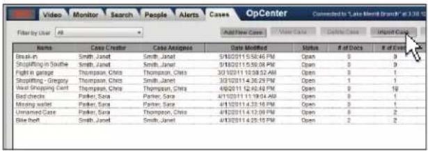
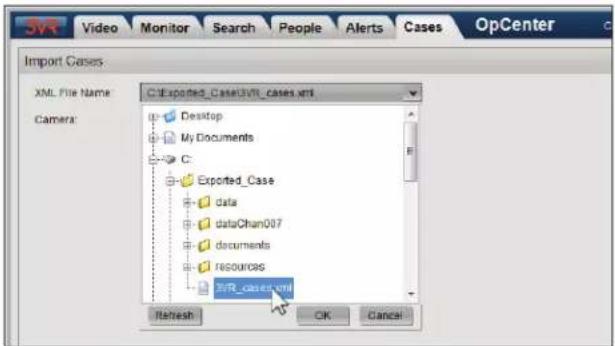
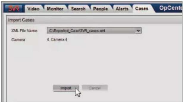

Notes
1) You cannot import a case that already exists in OpCenter. If you have exported a case, made modifications on a different appliance, and now wish to re-import it, you should delete the outdated case prior to importing.
2) Events imported with the case will have their original camera name and number replaced with the camera name and number of the import camera. In addition, the name of the source appliance will be changed to the destination appliance name.
4.2 Viewing Imported Cases
The imported case(s) will appear in the list of cases. To view the case details, select the case and click View Case.

5. IMPORTING PEOPLE
5.1 Importing People from XML
Use the following steps to import one or more people exported from another 3VR appliance:
- Launch 3VR OpCenter.
- Click the People tab.
-
Click Import People.
-
Select ( )XML as the import type.
-
Click the dropdown arrow next to XML File Name to open the file browser menu. Navigate to the export folder.
-
Select the 3VR_people.xml file and click OK.
-
Click Import to import the selected people.
- After the import is complete, click the Close button.


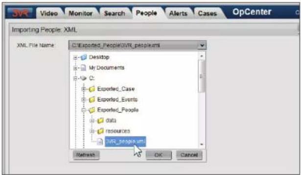
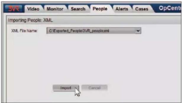

Details
People imported from XML will be placed into the group they belonged to on the source appliance. The group will be created if it does not exist. If an imported person already exists in OpCenter, the system will automatically sync any additions or deletions of face events/profiles that have been made elsewhere.
5.2 Importing People from Images
Use the following steps to create people in OpCenter based on a set of imported images:
- Launch 3VR OpCenter.
- Click the People tab.
-
Click Import People.
-
Select one of the following options as the import type:.
-
Manual: select people to import from a displayed list of images.
• Automatic: import people from all image files in a folder.


To import people from images, follow the instructions for the import type (automatic or manual):
Importing Images Automatically
Use the automatic importer to automatically create face events or people based on faces identified in a set of image files.
- Click the dropdown arrow next to Image Folder to open the file browser menu.
-
Select the folder containing the images to import, then click OK.
-
To import images in subfolders as well, check [ ] Include images in lower-level folders.
-
Specify what OpCenter should do with each imported face:
• To create a new person in the People panel for each imported face, select ( )Create a new person for each face.
- If you would like to import the images as face events, select ( )Index face but do not create a new person. You may manually create people from the imported face events after importing.
-
Specify how to handle duplicate image files:
-
Do not import duplicate image files.
- Do not import image files that match those already imported during this session.
- Allow duplicate image files.


vi. To provide a group name for the imported people other than the default value ("Imported People"), type a group name in the Set Identifier box.
vii. Click Import.
Importing Images Manually
If the automated importer cannot identify a face in a particular image, you may attempt to manually import it. This will give you the option to draw a box around each face and help the analytic locate it, though it is still possible for the image to be rejected if the analytic cannot find the face with the extra help.
Please note that images accepted in this manner will not be as "good" for searching as images accepted by the automatic importer.
- Click the dropdown arrow next to Image Folder to open the file browser menu.
- Select the folder containing the images to import, then click OK.
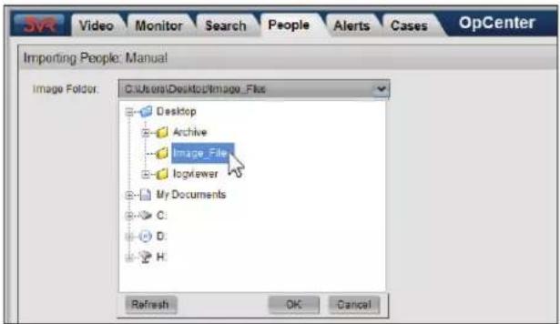
- Click Get Images.
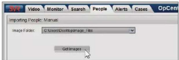
- Select an image file to import.
- If a face is found in the image file, the face will be identified with an orange box, with circles around the eyes.

- If the quality of an image is poor or if the face is at an angle, the facial surveillance analytic may fail to recognize a face when analyzing the full image. To assist with identification, click
and drag the mouse over the image to draw a box around the person's face.
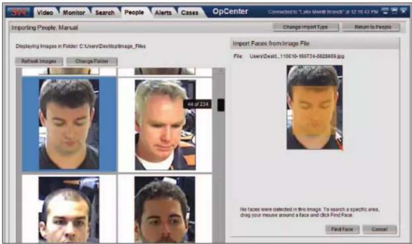
Click Find Face to re-run the face finding process.
- Click Import.
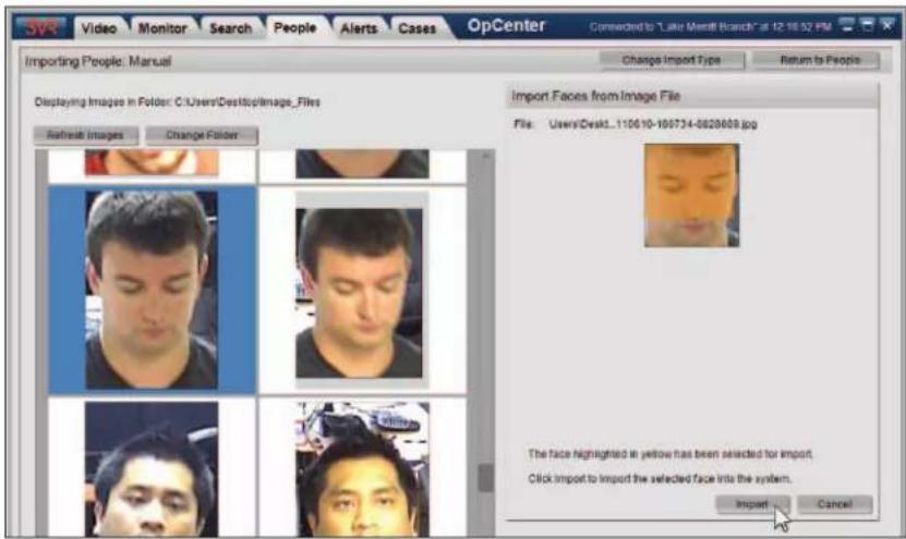
- Specify whether to []Create a new person with the imported image.
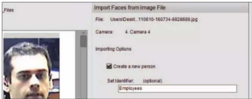
- To provide a group name for the imported people other than the default value ("Imported People"), type a group name in the Set Identifier box.
-
Click More Options.
-
Specify what OpCenter should do with each imported face:
-
If OpCenter should create a new person in the People panel for the imported face, select ( )Create a new person for each face.
If you would like to import the images as face events, select ( )Index face but do not create a new person. You may manually create people from the imported face events after importing. -
Specify how to handle duplicate image files:
-
Do not import duplicate image files.
- Allow duplicate images.
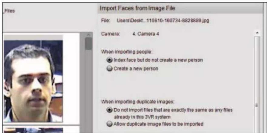
- Click Import to import the face.
Tips for Improving Import Results
In order to accept an image for importing, the analytic must be able to recognize a face in the image, which depends on identifying the person's eyes. A photo with a face could be rejected by the system if one or more of the following requirements is not met:
Size: The image must not be too big or too small. The ideal space between the eyes is 35-70 pixels — photos with larger faces should be resized.
Field of View: Faces that fill the whole image or are cropped by the image borders are difficult to identify.
File Type: if the images are JPGs, it is possible that the compression has created artifacts that can cause problems for the importer. If available, it is better to use a non-compressed format like PNG.
Accessories and Facial Hair: Accessories like hats or glasses can prevent importing. If available, it is better to use a photo of the person without accessories. Facial hair can also cause problems for the automatic importer. Use images without beards/goatees if possible.
Angle: Images used with the importer may not be recognized as faces if the horizontal and vertical angles of the face are too extreme. See Appendix A of the 3VR VIP Appliance Installation and Configuration Guide for more information and sample images.
Lighting: Lighting that is uneven, too dark, or too overexposed can prevent the system from recognizing a face. See Appendix A of the 3VR VIP Appliance Installation and Configuration Guide for more information and sample images.
5.3 Importing People from 3VR CrimeDex
To create people from suspects exported from 3VR CrimeDex:
- Launch 3VR OpCenter.
- Click the People tab.
-
Click Import People.
-
Select ( )CrimeDex as the import type.

More
To learn more about 3VR CrimeDex, an online community where anti-fraud, loss prevention, and law enforcement professionals collaborate to solve crimes faster, visit www.crimedex.com.
- Click the dropdown arrow next to Image Folder to open the file browser menu. Navigate to the folder containing the CrimeDex export file.
- Select the suspect-####.cdif file and click OK.

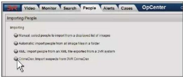

- To provide a group name for the imported people other than the default value ("CrimeDex Suspects"), enter a group name in the Set Identifier box.
- Click the Import button.
- After the import is complete, click the Close button.

5.4 Viewing Imported People
Imported People
Use the following steps to view imported people:
- Click the People tab to go to the People panel.
- Select Imported People (or the custom group name that was entered in the Set Identifier box when importing) from the groups filter at the top of the panel.

Imported Face Events
If you selected ( )Index face but do not create a new person when importing images, use the following steps to view the face events created from imported images:
- Click the Search tab to go to the Search panel
-
Set up a search with the following options:
-
Date and Time: Leave at default values, ( )Recent, 1 day and ( )Full week and ( )Full day.
- Cameras: Select the camera number of the image import camera.
- Events: Check the box next to [ ]Faces.
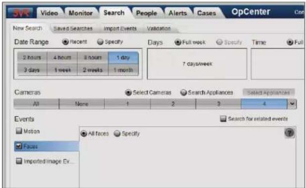
- Click the Search button.
The imported faces will appear in the Search panel results screen.
Click a face event card to open the event in the event editor. Edit the details in the Person tab and click Save to create a new person from the face.


Note
Face events created from imported images may also be viewed the Monitor panel for up to one hour after importing. Select the import camera and choose []Imported Images from the event type dropdown menu to view the events.
Imported CrimeDex Suspects
Use the following steps to view people imported from CrimeDex:
- Click the People tab to go to the People panel.
- Select CrimeDex Suspects from the groups filter at the top of the panel
- The People panel will update to only show person cards for people imported from CrimeDex.

CHAPTER 11
Report Viewer
1. INSTALLING REPORT VIEWER 154
1.1 System Requirements 154
1.2 Running the 3VR Client Application Installation Wizard 154
- SIGNING IN 156
3. REPORT VIEWER OVERVIEW 157
3.1 About Report Viewer 157
3.2 Report Viewer Layout 157
3.3 Resizing and Closing Report Viewer 157
3.4 Enterprise Report Viewer | Switching Between Appliances After Sign In 158
4. CREATING A NEW REPORT DEFINITION 159
4.1 Select Cameras 159
4.2 Select Event Types 159
4.3 Enterprise Report Viewer | Select Appliances 160
4.4 Edit Report Parameters 160
4.5 Edit Report Data 161
4.6 Create Reporting Schedule 162
4.7 Save Report Definition 162
5. MODIFYING AN EXISTING REPORT DEFINITION 163
5.1 Editing a Report Definition 163
5.2 Deleting a Report Definition 163
6. RUNNING REPORTS 164
6.1 Generating a Report 164
6.2 Viewing a Saved Report 165
6.3 Exporting and Printing Reports 166
6.4 Deleting Saved Reports 167
1. INSTALLING REPORT VIEWER
1.1 System Requirements
3VR Report Viewer™ client software allows you to access a 3VR VIP Appliance from any PC on your network that meets the minimum system requirements.
3VR Client Applications Minimum System Requirements
| Operating System | Windows XP Professional SP2 or later, Windows Vista, Windows 7 |
| Processor | Intel and AMD CPUs, 1.1 GHz or higherNote: Video playback performance will be dictated by CPU capabilities. |
| Display | Any display capable of 1024x768 resolution or greater |
| Video Card | DirectX 9-capable video graphics adapter |
| Memory | 1 GB RAM or greater |
| Storage | 1 GB available storage space |
| Bandwidth | Broadband connection (384 Kbps or greater) to 3VR server recommended. Greater bandwidth will result in a better user experience when viewing stored or live video. |
1.2 Running the 3VR Client Application Installation Wizard
Follow these steps to install one or more of the 3VR Client Applications on a PC.
- Double-click Installer-Client-Applications-7.0.1.xxxxx.exe to begin the installation process.
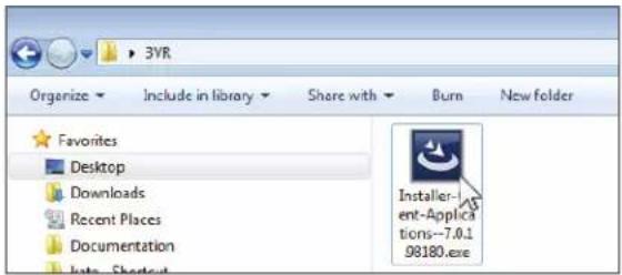
- The 3VR Client Applications require the Microsoft .NET Framework 4.0 to function.
If Microsoft .NET Framework 4.0 is not present on your PC, the InstallShield Wizard will install it as the first step in the installation process.
Click Install to proceed.

Note
It may take up to 5 minutes to install Microsoft .NET Framework 4.0.

- At the InstallShield Wizard Welcome screen, click Next >.

- The InstallShield Wizard will display the 3VR Client Applications End User License Agreement.
Read the agreement, then select ( )I accept the terms in the license agreement and click Next >.
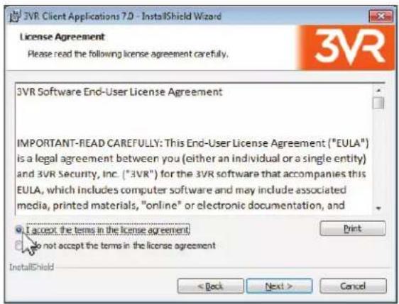
- Specify the installation type:
• To install 3VR Report Viewer, select ( ) Custom and click Next >.

- Click the red X next to 3VR Report Viewer and select This Feature, and all subfeatures, will be installed on local hard drive. Click Next >.

- Click Install to begin the installation.
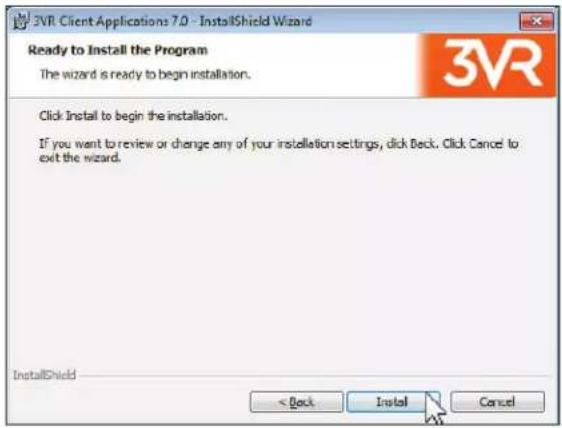
- When installation is complete, click Finish to exit the wizard.

2. SIGNING IN
Follow these steps to sign in to Report Viewer.
-
Double-click the 3VR Report Viewer desktop icon to launch the application. Alternatively, click the Windows Start menu > All Programs > 3VR Client Applications 7.0 > 3VR Report Viewer.
-
At the sign in screen, enter the User Name and Password of your 3VR user account.
-
Select an appliance to connect to:
- If this is your first time signing in to Report Viewer on this PC, type the IP address of the 3VR system in the Appliance box. This is the address provided to you by the 3VR administrator, in the format XXX.XXX.XXX.XXX (four 1-3 digit numbers separated by periods). For example, 10.100.2.22.

- If you have signed into Report Viewer previously on this PC, open the Appliance dropdown menu and select the system to connect to.
- Click Sign In.
3. REPORT VIEWER OVERVIEW
3.1 About Report Viewer
The 3VR Report Viewer client application allows you to generate tabular reports based on data captured by the 3VR system.
There are two basic types of reports: event reports and counting reports.
Event Reports
Event reports are generated based on the properties of events present on the 3VR appliance or Enterprise. Depending on the event types that exist on the system, event reports may be used to perform queries such as:
• How many motion events occurred?
• How many faces similar to a given face were captured?
• How many license plates containing a certain character combination were recorded?
over a certain time period. You can further restrict the parameters of an event report by the source camera and appliance (for Enterprise Report Viewer).
Counting Reports
Counting reports are used to view the results of the 3VR VIP People Counting plug-in.

Reference
See the 3VR People Counting User Guide for more information about People Counting and counting reports.
3.2 Report Viewer Layout
The Report Viewer home screen is organized in a grid layout with four panels:
Report Definitions
A report definition is a set of parameters used to generate a report. This panel displays the list of all report definitions that have been created on the appliance. Report definitions can be sorted by name, type, and creator.
Report Description
When a report definition is selected, the Report Description panel displays a summary of the report definition's parameters.

Saved Reports
Each time a report definition is used to generate a report (either run manually or as a scheduled report), the report is saved in the Saved Reports panel. Saved reports can be sorted by the report name, completion date, and user name.
Pending Reports
Reports that are in the process of being generated will appear in the Pending Reports panel until completion, at which point they will move to the Saved Reports panel.
3.3 Resizing and Closing Report Viewer
3VR Report Viewer can be minimized and maximized in the same way as any other Windows application using the controls in the upper-right corner.
To close Report Viewer, click the X button.
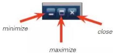
To customize the size of the Report Viewer window, click and drag any edge of the window until it has reached the desired size.
Click and drag a corner of the window to resize the window vertically and horizontally at the same time.

3.4 Enterprise Report Viewer | Switching Between Appliances After Sign In
Immediately after signing in to Enterprise Report Viewer, the user selects the initial VIP Appliance to connect to from the appliance selector. Thereafter, the active appliance is displayed in status bar in the top-right corner of Report Viewer.
To switch to a different appliance on the Enterprise:
- Click the 3VR button in the top-left corner of the application and select Connect to Appliance from the options menu.
- When the appliance selector loads, select a new appliance from the list, then click Sign In.


4. CREATING A NEW REPORT DEFINITION
Use the following steps to create a new report definition:
- From the Report Viewer home screen, click the New button.
- Select Event Report from the menu.
- Report Viewer will switch to the report editing screen. From this screen you will specify the cameras and event types to include in the report definition, as well as parameters like the report name, description, and scope. See the following sections for detailed information about each option.

4.1 Select Cameras
Use the camera selector to specify which cameras to include in the report:

- Select cameras individually by clicking each camera number.
• To select all cameras on the appliance, click All. - To run the report on all cameras in a camera group, click the dropdown arrow at the end of the camera selector, then select the camera group name.

Reference
See Chapter 3: Monitor Panel for detailed information about the camera selector, including defining camera groups.
4.2 Select Event Types
The event selector displays the list of event types available on the appliance (or the active appliance, if you are logged in to Enterprise Report Viewer).
Check the box next to the event type(s) of interest under the Events header. You must select at least one event type.
By default, the report will be run on all events of the selected type. However, most event types allow you to further restrict the report by selecting the ( )Specify radio button in the event selector.
For example, to run a report counting all faces similar to a known face:
- In the event selector, check the box next to [ ]Faces to report on face events.
- Select ( )Specify.
- Select [ ]People and Characteristics, then click ( )Person.
- Select the face to report on for from the list of known people.


Notes
1) See Chapter 4: Search Panel for detailed information about configuring the ( )Specify options for face events and alarm events. For event types generated by plug-ins (for example, transaction events) please consult the plug-in documentation.
2) The Faces event type will not be listed unless facial surveillance has been enabled and configured on one or more cameras.
4.3 Enterprise Report Viewer | Select Appliances
The Appliances panel of the Report Viewer report editing screen allows you to select which appliances to run the report on.
- Check the box next to an appliance name to include it in the report definition.
• To run the report on an entire region, check the box next to a region name.

Note
When connected to a standalone appliance, the Appliances panel will display a read-only field with the appliance name pre-selected.

flowchart
graph TD
    A["Enterprise Appliance"] --> B["Arizona"]
    A --> C["Tucson"]
    A --> D["California"]
    A --> E["Los Angeles"]
    A --> F["San Francisco"]
    A --> G["Texas"]
    A --> H["Dallas"]
4.4 Edit Report Parameters
The fields under Report Parameters allow you to define the metadata of the report definition, such as its name and scope:
- Type a Name for the report definition and a brief Description of its parameters.

-
Open the Date Range menu and specify the date range for the report in one of the following ways:
-
Choose one of the pre-defined date range options, such as Yesterday.
- To run the report on a custom date range, select Specify from the Date Range menu. Specify the start and end date using the calendar controls.
- Choose one of the pre-defined date range options, such as Yesterday.
- To run the report on a custom date range, select Specify from the Date Range menu. Specify the start and end date using the calendar controls.

-
If the selected Date Range is one day or longer, you can use the Time Scope menu to restrict the report to a certain time of the day in one of the following ways:
-
Choose one of the pre-defined time scopes, such as 12am to 6am.
-
To run the report with a custom time scope, select Specify from the Time Scope menu. Specify the start and end time using the time controls.
• To run the report on the full day, leave the Time Scope menu set to All Day (the default value). -
The Interval setting determines the time interval to use for report subtotals.
-
For a broad overview report, select a longer time interval, such as 2 Hours.
• For a detailed report, select a shorter time interval, such as 15 Minutes. -
To display the report with the time intervals adjusted to the hour, select []Align time intervals to the hour.

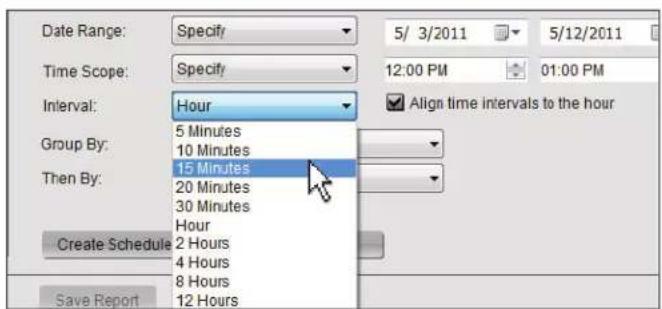
This will shift the time intervals to start at the hour, regardless of the actual start time. For example, a report run over the last hour with an interval of 5 minutes will tally events from :00 to :05, then :05 to :10, and so on instead of from :02 to :07, :07 to :12, etc.
- The Group by and Then by dropdown menus allow you to change the grouping of data in the report. The options that appear will depend on the event type(s) included in the report.

4.5 Edit Report Data
By default, event reports are generated based on the count function (counting the number of matching events occurring over a time period). The Edit Report Data menu contains additional functions that may be run on the data and output with the report.
- Click Edit Report Data.
- In the Edit Report Data dialog, select the functions that should be run on the event data and included in the report output.
| Property Description Functions | |
| Event Whether an event occurred Count | |
| Event Duration The length, in seconds, of the event video clip Minimum, Maximum, Sum, Average, Standard Deviation |

Note
Events generated by plug-ins may populate more options in the Edit Report Data than what is shown here.
Consult the plug-in specific user guide for more information.
- Click Save to return to the report editing screen.
4.6 Create Reporting Schedule
When creating or editing a report, you can define a schedule to automatically run the report at regular intervals.
- From the report editing screen, click Create Schedule.
- Define how frequently you want to run the report, from once per hour to once per month.
-
Specify a destination for the report results:
-
Select [ ]Email to send the report results via email. Enter a From address, a Subject line, and one or more email recipients separated by commas.
-
Select [ ]Save to Server to have the report results stored for later viewing in Report Viewer (saved reports will be listed in the main Report Viewer screen).
-
Click Save to return to the report editing screen.

4.7 Save Report Definition
When you are finished creating or editing a report definition, click the Save Report button at the bottom of the report editing screen to save your changes.

5. MODIFYING AN EXISTING REPORT DEFINITION
5.1 Editing a Report Definition
To edit the parameters of a saved report definition:
- Select the definition from the list.
- Click Edit.
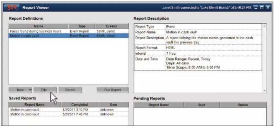
- You will be returned to the Report Viewer report editing screen. Make changes as desired.
- When you are finished, click Save Report to save the report definition.
5.2 Deleting a Report Definition

Warning
Deleting a report definition will also delete all saved reports associated with the definition. Deleting a report definition is permanent and cannot be undone.
To delete a saved report definition:
- Select the definition from the list.
- Click Delete.
- In the confirmation dialog that appears, click Delete again to delete the report definition and associated saved reports.

6. RUNNING REPORTS
6.1 Generating a Report
To generate a report from a saved report definition, select the definition from the list and click Run Report.
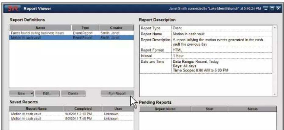
Report Viewer will immediately begin generating the report. While the report is processing, it will appear under Pending Reports.
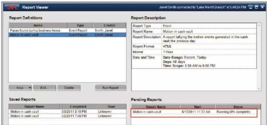
When the report has been processed, it will move to the list of Saved Reports that have been generated from the report definition.
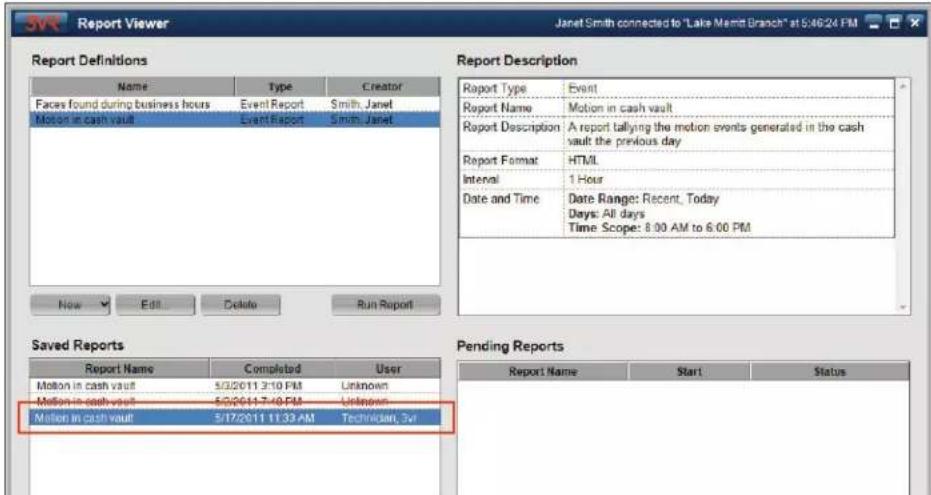
6.2 Viewing a Saved Report
Reports that have been generated manually or by a report schedule (see section 4.7) will appear in the Saved Reports panel.
To view a saved report:
- Select the saved report.
- Click View.

- A window will appear with a preview of the report.

6.3 Exporting and Printing Reports
After previewing a saved report (see section 6.2), you can export the report from Report Viewer for use in other applications, or the report may be emailed directly from Report Viewer.
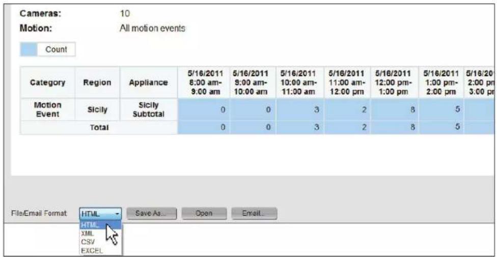
To save the report to disk:
- From the report preview screen, click the File/Email Format dropdown list and select the file format for the report (HTML, XML, CSV, or XLS).
- Click Save As.
- In the Save Report to Folder dialog, select the directory or drive where you wish to save the report file.
- Edit the file name if desired. By default, the report file name will contain the name of the report and the date the report was run.
- Click the Save button to save the report.

To open the report in another application:
- From the report preview screen, click the File/Email Format dropdown menu and select the file format for the report (HTML, XML, CSV, or XLS).
- Click Open.
- The report file will open in the application on your computer that has been associated with the file type. For example, if the File/Email Format is set to Excel, clicking Open will open the report in Microsoft Excel, OpenOffice Calc or another spreadsheet application.

Note
If the selected file type is not associated with an application on your PC, you will be prompted to choose the appropriate program for the file. For best results, open the report file in the following applications:
• For CSV or XLS: Microsoft Excel
• For HTML: Internet Explorer or another web browser
To email the report:
- From the report preview screen, click the File/Email Format dropdown menu and select the file format for the report (HTML, XML, CSV, or XLS).
- Click Email.
- Type one or more email addresses in the resulting box. If sending the report to multiple email recipients, separate the addresses with a comma.
- Click Send Email. The report will be sent to the address(es) as an attachment.
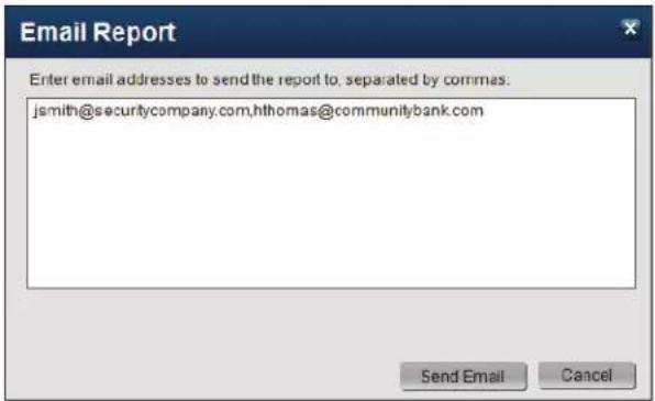
To print the report:
- From the report preview screen, click the File/Email Format dropdown menu and select HTML.
- Click Open. The file will open in your PC's default web browser.
- Hold the CTRL key and press P to access the print dialog.
- Click Print.
6.4 Deleting Saved Reports
Reports that have been saved to the appliance may be deleted with the following steps:
- Select the saved report to delete from the Saved Reports panel.
- Click Delete.
- In the confirmation dialog that pops up, click Delete to confirm that the saved report should be permanently deleted.

CHAPTER 12
Spot Monitor
- INSTALLING SPOT MONITOR 168
1.1 System Requirements 168
1.2 Running the 3VR Client Application Installation Wizard 168 - SIGNING IN 170
- SPOT MONITOR OVERVIEW 171
3.1 About Spot Monitor 171
3.2 Resizing and Closing Spot Monitor 171 - CONFIGURING SPOT MONITOR 172
4.1 Sequential View 172
4.2 Multiplex View 173 - WATCHING SPOT MONITOR 175
1. INSTALLING SPOT MONITOR
1.1 System Requirements
3VR Spot Monitor™ client software allows you to access a 3VR VIP Appliance from any PC on your network that meets the minimum system requirements.
3VR Client Applications Minimum System Requirements — Single Display
| Operating System | Windows XP Professional SP2 or later, Windows Vista, Windows 7 |
| Processor | Intel and AMD CPUs, 1.1 GHz or higherNote: Video playback performance will be dictated by CPU capabilities. |
| Display | Any display capable of 1024x768 resolution or greater |
| Video Card | DirectX 9-capable video graphics adapter |
| Memory | 1 GB RAM or greater |
| Storage | 1 GB available storage space |
| Bandwidth | Broadband connection (384 Kbps or greater) to 3VR server recommended. Greater bandwidth will result in a better user experience when viewing stored or live video. |
3VR Spot Monitor™ 7.0 features support for multiple displays. Users intending to stream video on more than one monitor must also meet the additional requirements for multi-screen display:
Additional Requirements for Multi-Screen Display
| Processor | Intel and AMD CPUs, 3.0 GHz or higher |
| Video Card | DirectX 9-capable video graphics adapter with support for multiple displays |
| Memory | 2 GB RAM or greater |
1.2 Running the 3VR Client Application Installation Wizard
Follow these steps to install one or more of the 3VR Client Applications on a PC.
-
Double-click Installer-Client-Applications-7.0.1.XXXXX.exe to begin the installation process.
-
The 3VR Client Applications require the Microsoft .NET Framework 4.0 to function.
If Microsoft .NET Framework 4.0 is not present on your PC, the InstallShield Wizard will install it as the first step in the installation process.
Click Install to proceed.

Note
It may take up to 5 minutes to install Microsoft .NET Framework 4.0.


-
At the InstallShield Wizard Welcome screen, click Next >.
-
The InstallShield Wizard will display the 3VR Client Applications End User License Agreement.
Read the agreement, then select
( )I accept the terms in the license agreement and click Next >.
- Specify the installation type:
• To install 3VR Spot Monitor, select ( ) Custom and click Next >.
- Click the red X next to 3VR Spot Monitor and select This Feature, and all subfeatures, will be installed on local hard drive. Click Next >.


-
Click Install to begin the installation.
-
When installation is complete, click Finish to exit the wizard.
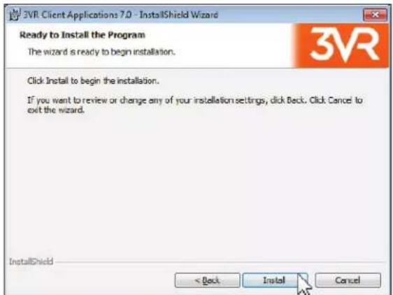

2. SIGNING IN
Follow these steps to sign in to Spot Monitor.
-
Double-click the 3VR Spot Monitor desktop icon to launch the application. Alternatively, click the Windows Start menu > All Programs > 3VR Client Applications 7.0 > 3VR Spot Monitor.
-
At the sign in screen, enter the User Name and Password of your 3VR user account.
-
Select an appliance to connect to:
-
If this is your first time signing in to Spot Monitor on this PC, type the IP address of the 3VR system in the Appliance box. This is the address provided to you by the 3VR administrator, in the format XXX.XXX.XXX.XXX (four 1-3 digit numbers separated by periods). For example, 10.100.2.202.
-
If you have signed into Spot Monitor previously on this PC, open the Appliance dropdown menu and select the system to connect to.
-
Click Sign In.
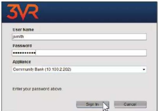
3. SPOT MONITOR OVERVIEW
3.1 About Spot Monitor
3VR VIP Spot Monitor is a simple application that streams a multiplex or cycling display of live video from a 3VR appliance. Spot Monitor should be installed instead of OpCenter for 3VR users who only need to monitor live video, for example at a security guard watch station or PC used to create a public display monitor.

Note
This chapter outlines the features of the 3VR Spot Monitor client application. For instructions on installing and configuring a Spot Monitor connected to the BNC output of the appliance, see the 3VR VIP Appliance Installation and Configuration Guide.
3.2 Resizing and Closing Spot Monitor
3VR Spot Monitor can be minimized and maximized in the same way as any other Windows application using the controls in the upper-right corner.
To close Spot Monitor, click the X button.
To customize the size of the Spot Monitor window, click and drag any edge of the window until it has reached the desired size.
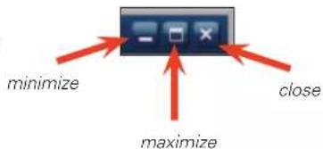
Click and drag a corner of the window to resize the window vertically and horizontally at the same time.

natural_image
Interior view of an office with a person at a desk, patterned flooring, and large windows (no visible text or symbols)4. CONFIGURING SPOT MONITOR
To modify the cameras or sequence of the Spot Monitor display, move the cursor to the top of the monitor to display the Spot Monitor title bar. Click the 3VR button in the upper left-hand corner and select Configure from the dropdown menu.

The settings in this dialog control the appearance and behavior of Spot Monitor. First, choose the view mode for Spot Monitor:
• To display live video from one camera at a time in a cycling display, select ◎ Sequential View. Continue to section 4.1.
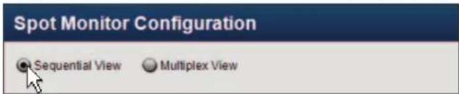
• To display live video from multiple cameras at the same time, select ◎ Multiplex View. Continue to section 4.2.

4.1 Sequential View
When Spot Monitor is configured with sequential view, cameras will be displayed on the Spot Monitor one at a time, in ascending order by camera number, at full-screen resolution.
- Click the camera number of each camera to include in the sequence.
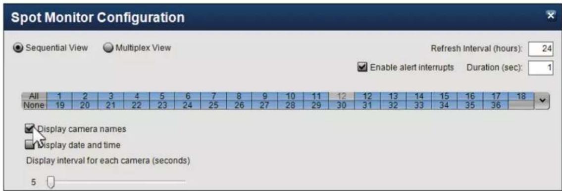
- Select the information that should be placed as an overlay on each camera:
• [ ]Display camera names
• [ ]Display date and time
- To display alerts generated by the 3VR system in Spot Monitor, check [ ]Enable alert interrupts.
Enter the length of time for alert interrupts into the Alert interrupt duration text box. When an alert is generated on the system, it will be displayed on the monitor in place of the live video feed for this length of time.
- The Spot Monitor application will restart itself periodically to ensure the application continues to run smoothly for days and weeks at a time. By default, the restart will occur once every 24 hours, but you may set a different restart interval in the Refresh Interval (hours) box.
- Use the slider bar under Display interval for each camera (seconds) to specify the number of seconds each camera should be displayed.
- Click OK to save the configuration and return to the Spot Monitor main screen.
4.2 Multiplex View
When Spot Monitor is configured with multiplex view, cameras will be displayed on the Spot Monitor simultaneously in the number and arrangement of your choice.
- Choose a layout for the Spot Monitor with the layout selector. Click a new layout button to increase or decrease the number and positioning of players as desired. Up to 36 cameras can be displayed at a time in Spot Monitor.
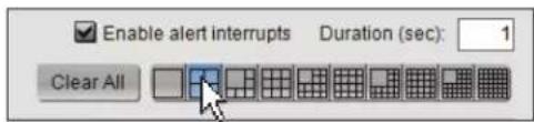
- When you have decided on a player layout, click and drag a camera from the camera tree to each blank video player.

Live video from the selected cameras will stream in each position in the video grid.
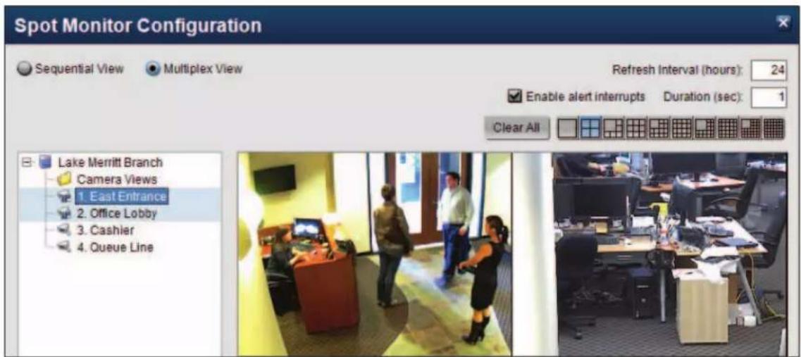
If you would like to display information about the camera on top of each video player, change the camera overlays with the following steps:
-
Right-click anywhere in the video grid.
-
Select Overlays >, then choose an overlay from the sub-menu. The current overlay options are:
-
No Overlay
- Camera Name
• Camera Number and Name
• Appliance and Camera Number/Name
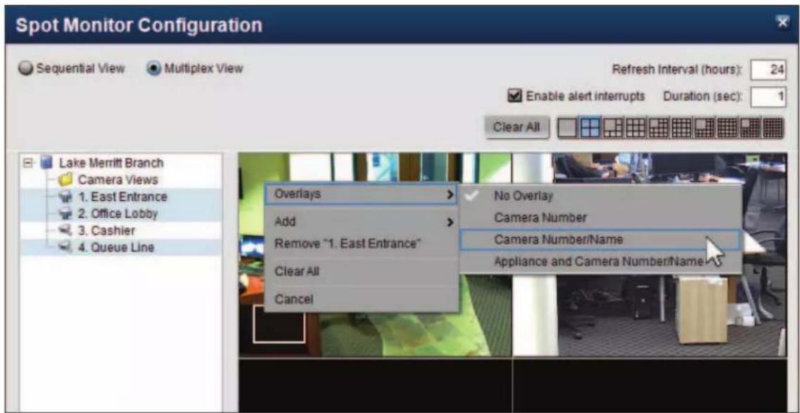
- To display alerts generated by the 3VR system in Spot Monitor, check [ ]Enable alert interrupts.
Enter the length of time for alert interrupts into the Alert interrupt duration text box. When an alert is generated on the system, it will be displayed on the monitor in place of the live video feed for this length of time. - The Spot Monitor application will restart itself periodically to ensure the application continues to run smoothly for days and weeks at a time. By default, the restart will occur once every 24 hours, but you may set a different restart interval in the Refresh Interval (hours) box.
- Click OK to save the configuration and return to the Spot Monitor main screen.
5. WATCHING SPOT MONITOR
After clicking OK from the Spot Monitor configuration screen (section 3), Spot Monitor will load with the selected camera(s) streaming live video.

By default, camera overlays are placed in the top-left corner of each video player. If desired, you can re-position the overlay by clicking and dragging the overlay box.

Start
End
- 3VR VIDEO INTELLIGENCE PLATFORM™
- 3VR USER MANUAL 7.0
- CHAPTER 1: OPCENTER BASICS
- CHAPTER 2: VIDEO PANEL
- CHAPTER 3: MONITOR PANEL
- CHAPTER 4: SEARCH PANEL
- SEARCHING FROM AN EVENT OR PERSON CARD 80
- CHAPTER 5: ALERTS PANEL
- GETTING STARTED WITH THE ALERTS PANEL 84
- CHAPTER 6: CASES PANEL
- GETTING STARTED WITH THE CASES PANEL 94
- CHAPTER 7: PEOPLE PANEL
- CHAPTER 8: NOTES
- CHAPTER 9: VIEWING EXPORTED EVIDENCE
- CHAPTER 10: IMPORTING
- CHAPTER 11: REPORT VIEWER
- CHAPTER 12: SPOT MONITOR
- CHAPTER 1
- OpCenter Basics
- INSTALLING OPCENTER 38
- INSTALLING OPCENTER
- System Requirements
- Running the 3VR Client Application Installation Wizard
- Note
- SIGNING IN
- Signing in to OpCenter
- Trouble Signing In?
- Enterprise OpCenter | Selecting an Appliance
- Managing the Appliance List
- Viewing the Appliance List
- Manually Adding an Appliance to the List
- Editing or Removing a Saved Appliance
- Finding Appliances on the Local Network
- OPCENTER OVERVIEW
- OpCenter Panel Layout
- Video Panel
- Monitor Panel
- Search Panel
- Alerts Panel
- Cases Panel
- People Panel
- Resizing and Closing OpCenter
- Enterprise OpCenter | Switching Between Appliances After Sign In
- OPCENTER ADMINISTRATION
- Changing Your 3VR Password
- Setting the Company Name
- Resetting OpCenter to Default Settings
- Viewing and Copying Appliance Information
- CHAPTER 2
- GETTING STARTED WITH THE VIDEO PANEL
- CUSTOMIZING THE VIDEO PANEL
- Changing the Number and Size of Video Players
- More
- Tip
- Adding and Removing Cameras
- Adding Cameras With Drag and Drop
- Adding Cameras With Right-Click Menus
- Removing Cameras
- Camera Views
- Saving a New Camera View
- Loading a Saved View
- Deleting a Saved View
- Camera Overlays
- Showing or Hiding the Video Timeline and Camera Tree
- Switching to Full Screen Mode
- Video Playback Options
- Stored Video Fidelity Mode
- Live Video Alternate Streams
- - Analog cameras
- • IP cameras
- VIEWING LIVE AND STORED VIDEO
- Live Video
- Stored Video
- Video Playback Controls
- PTZ CAMERA CONTROLS
- Overview
- Important
- Click to Center Mode:
- Compass Mode
- Click to Center Mode
- Joystick Mode
- Preset Views
- Selecting a Preset View
- Saving a New Preset View
- Editing a Saved Preset View
- Tours
- Recording a New Tour
- Renaming or Deleting a Tour
- PTZ Camera Focus and Iris Control
- Manual Focus Control
- Manual Iris Control
- DIGITAL ZOOM
- Entering Zoom Mode
- Zooming with the Mouse Scroll Wheel
- Zooming While Holding the Ctrl Key
- Shifting the Zoomed Region
- Exiting Zoom Mode
- OPENING A SECOND VIDEO PANEL
- Notes
- PANORAMIC STITCHING
- Creating a New Stitched View
- Loading a Saved Stitched View
- EXPORTING VIDEO AND IMAGES FROM THE VIDEO PANEL
- Exporting Video
- Details
- Saving a Single Frame as an Image
- CHAPTER 3
- GETTING STARTED WITH THE MONITOR PANEL
- VIEWING EVENTS
- Event Card Types
- Motion Event Cards
- Face Event Cards\*
- External Input/Alarm Event Cards
- Reference
- Alert Event Cards
- Note Event Cards
- Event Video
- Event Details
- - Notes
- - Images
- - Person
- - Properties
- - Cases
- - Alerts
- - Details
- CUSTOMIZING THE MONITOR PANEL
- Changing the Time Interval
- Changing the Appearance of Event Cards and Event Images
- Showing or Hiding the Event Editor and Video Player
- USING THE CAMERA SELECTOR
- Viewing Camera Names
- Selecting Cameras Individually
- Standard Mode
- Toggle Mode
- Selecting Multiple Cameras and Camera Groups
- Creating a Camera Group
- Editing or Deleting a Camera Group
- VIEWING EVENT VIDEO IN THE POP-UP VIDEO PLAYER
- VIEWING LIVE VIDEO IN THE MONITOR PANEL
- EXPORTING IMAGES
- Image Quick Save
- Saving Images to an Event Card
- Enhancing Images
- Exporting Images
- Printing Images
- Emailing Images
- EXPORTING EVENTS
- Printing Events
- Emailing Events
- Exporting Events
- Export Event
- CHAPTER 4
- GETTING STARTED WITH THE SEARCH PANEL
- BUILDING A SEARCH
- Specify Date and Time Range
- Date Range
- Days
- Time
- Select Cameras
- Enterprise OpCenter | Select Appliances
- Select Event Types
- Motion Events
- Face Events\*
- Alarm Events
- Alert Events
- Note Events
- Reviewing Search Criteria and Running the Search
- VIEWING SEARCH RESULTS
- ADVANCED SEARCH OPTIONS
- Searching for Correlated Events
- Searching for Motion in a Region
- Rectangular Region
- Custom Region
- Click Search.
- Searching for Specific Faces
- Searching for Faces Similar to a Person
- Click Search.
- Searching for Faces Not Matching a Person
- Searching for Faces Similar to Members of a Group
- Searching for User-Defined Person Characteristics
- Sorting Search Results
- SAVING SEARCHES
- Storing Search Criteria as a Saved Search
- Running a Saved Search
- Modifying or Deleting a Saved Search
- SEARCHING FROM AN EVENT OR PERSON CARD
- Search for Camera
- Search for Time
- Search for Person
- EXPORTING SEARCH RESULTS
- CHAPTER 5
- GETTING STARTED WITH THE ALERTS PANEL
- CREATING AN ALERT
- Set Alert Name and Color
- Select Days and Times
- Select Cameras
- Specify Alert Action
- Outline Alert Response Procedure
- Save and Enable the New Alert:
- ALERT ACTIONS
- Viewing Alert Actions
- of Seconds: 120
- Configuring a New Email Alert Action
- Creating a New Settings Change Alert Action
- Important Notes
- VIEWING ALERT EVENTS
- CHAPTER 6
- GETTING STARTED WITH THE CASES PANEL 92
- ADDING SUPPORTING DOCUMENTS AND NOTES TO A CASE 97
- GETTING STARTED WITH THE CASES PANEL
- Cases Panel Overview
- Cases Panel Layout
- WORKING WITH CASES
- Viewing an Existing Case
- Opening a New Case
- From an Event or Person Card
- Editing a Case
- Deleting a Case
- BUILDING A CASE
- Adding Events to a Case
- Adding a Single Event Card
- Adding Multiple Events at Once
- Adding a Person to a Case
- Removing Evidence from a Case
- ADDING SUPPORTING DOCUMENTS AND NOTES TO A CASE
- Adding a Document to a Case
- Working with Documents
- Opening a Document
- Saving a Document
- Removing a Document
- Adding Notes to a Case
- EXPORTING A CASE
- CHAPTER 7
- GETTING STARTED WITH THE PEOPLE PANEL
- Licensed Feature
- WORKING WITH FACE EVENTS
- Creating a New Person from a Face Event
- Matching a Face Event to an Existing Person
- FILTERING AND SORTING PERSON CARDS
- Filtering People by Group Membership
- Sorting People Chronologically
- Filtering People by Name, ID, Gender, and Other Custom Properties
- PEOPLE GROUPS
- Creating a New Group
- Editing People Groups
- Deleting People Groups
- VIEWING AND EDITING PERSON DETAILS
- WORKING WITH PERSON PROFILES
- Viewing Profiles Matched to a Person Card
- Changing the Display Profile
- Unmatching a Profile from a Person Card
- Person Profile Images
- Viewing Profile Images
- Changing the Display Image for the Profile
- Unmatching a Profile Image from a Profile
- MERGING TWO PERSON CARDS
- EXPORTING PEOPLE
- Exporting People
- Enterprise OpCenter | Exporting People to Another Appliance
- CHAPTER 8
- ABOUT NOTES
- Notes Overview
- Viewing a Note
- ADDING A NOTE
- Warning
- Adding a Note
- Re-Labeling a Note
- MANAGING NOTE LABELS
- Creating a Custom Note Label
- Editing or Deleting a Note Label
- CHAPTER 9
- Viewing Exported Evidence
- VIEWING EXPORTED EVENTS, PEOPLE, AND CASES
- VIEWING EXPORTED VIDEO
- Viewing Exported Video in Evidence Viewer
- Viewing Exported Video in a Supported Media Player
- EVIDENCE VIEWER OVERVIEW
- About Evidence Viewer
- Obtaining Evidence Viewer
- OPENING EXPORTED VIDEO IN EVIDENCE VIEWER
- Automatically Load Video from Export Folder
- Manually Select Export Folder
- REVIEWING VIDEO IN EVIDENCE VIEWER
- Controlling Video Playback
- Saving a Single Frame as an Image
- CUSTOMIZING EVIDENCE VIEWER
- Changing the Number and Size of Video Players
- Adding and Removing Cameras
- Camera Overlays
- Showing or Hiding the Video Timeline and Camera Tree
- DIGITAL ZOOM
- Entering Zoom Mode
- Shifting the Zoomed Region
- Exiting Zoom Mode
- VALIDATING EXPORTED EVIDENCE
- About Evidence Validation
- Validating Exported Events, People, and Cases in 3VR OpCenter
- Validating Exported Video in 3VR Evidence Viewer
- Validation Exception(s)
- CHAPTER 10
- Importing
- IMPORTING OVERVIEW
- CONFIGURE IMPORT CAMERA ON APPLIANCE
- IMPORTING EVENTS
- Importing Events from XML
- Importing Events from Video
- Viewing Imported Events
- Events Imported from Video
- IMPORTING CASES
- Importing Cases from XML
- of Docs # of Excel
- Viewing Imported Cases
- IMPORTING PEOPLE
- Importing People from XML
- Importing People from Images
- Importing Images Automatically
- Importing Images Manually
- Tips for Improving Import Results
- Importing People from 3VR CrimeDex
- Viewing Imported People
- Imported People
- Imported Face Events
- Imported CrimeDex Suspects
- CHAPTER 11
- Report Viewer
- INSTALLING REPORT VIEWER 154
- REPORT VIEWER OVERVIEW 157
- CREATING A NEW REPORT DEFINITION 159
- MODIFYING AN EXISTING REPORT DEFINITION 163
- RUNNING REPORTS 164
- INSTALLING REPORT VIEWER
- REPORT VIEWER OVERVIEW
- About Report Viewer
- Event Reports
- Counting Reports
- Report Viewer Layout
- Report Definitions
- Report Description
- Saved Reports
- Pending Reports
- Resizing and Closing Report Viewer
- Enterprise Report Viewer | Switching Between Appliances After Sign In
- CREATING A NEW REPORT DEFINITION
- Select Cameras
- Select Event Types
- Enterprise Report Viewer | Select Appliances
- Edit Report Parameters
- Edit Report Data
- Create Reporting Schedule
- Save Report Definition
- MODIFYING AN EXISTING REPORT DEFINITION
- Editing a Report Definition
- Deleting a Report Definition
- RUNNING REPORTS
- Generating a Report
- Viewing a Saved Report
- Exporting and Printing Reports
- To save the report to disk:
- To email the report:
- To print the report:
- Deleting Saved Reports
- CHAPTER 12
- Spot Monitor
- INSTALLING SPOT MONITOR
- SPOT MONITOR OVERVIEW
- About Spot Monitor
- Resizing and Closing Spot Monitor
- CONFIGURING SPOT MONITOR
- Sequential View
- Multiplex View
- WATCHING SPOT MONITOR
Brand : 3VR
Model : VisionPoint 55
Category : Security Camera