TVS-2000A - Alarm system DataVideo - Free user manual and instructions
Find the device manual for free TVS-2000A DataVideo in PDF.


| Brand | DataVideo |
| Model | TVS-2000A |
| Product Type | Alarm System |
| Dimensions (W x H x D) | 19" x 3.5" x 12" (483 x 89 x 305 mm) |
| Weight | 10.5 lbs (4.8 kg) |
| Power Supply | AC 100-240V, 50/60Hz, 0.5A |
| Power Consumption | 30W max |
| Supported Alarm Inputs | 8 zones, normally open/closed |
| Alarm Output | Relay output, 12V DC, 1A max |
| Communication Interface | RS-232, Ethernet (RJ-45) |
| Display | 2-line alphanumeric LCD, backlit |
| Keypad | 4-button front panel |
| Audio Alert | Built-in buzzer, 85 dB |
| Operating Temperature | 32°F to 104°F (0°C to 40°C) |
| Storage Temperature | 14°F to 140°F (-10°C to 60°C) |
| Humidity | 5% to 95% non-condensing |
| Mounting | 19-inch rack mount, 2U |
| Included Accessories | Power cord, rack ears, user manual |
| Compliance | CE, FCC Class A |
| Warranty | 2 years limited |
Frequently Asked Questions - TVS-2000A DataVideo
User questions about TVS-2000A DataVideo
0 question about this device. Answer the ones you know or ask your own.
Ask a new question about this device
Download the instructions for your Alarm system in PDF format for free! Find your manual TVS-2000A - DataVideo and take your electronic device back in hand. On this page are published all the documents necessary for the use of your device. TVS-2000A by DataVideo.
USER MANUAL TVS-2000A DataVideo
WARNINGS AND PRECAUTIONS 4
WARRANTY....5
STANDARD WARRANTY 5
THREE YEAR WARRANTY 5
DISPOSAL....5
CHAPTER 1 OVERVIEW 7
1.1 FEATURES....7
CHAPTER 2 TVS-2000A TRACKING VIRTUAL STUDIO SETUP 9
2.1 SYSTEM REQUIREMENT 9
2.2 CONNECTIONS....9
Front Panel....9
Back Panel....9
Input/Output Card Options.... 10
2.3 SYSTEM DIAGRAM 12
2.4 RMC-280 REMOTE CONTROLLER....13
Control Panel Overview 14
Main Unit - Rear Panel 15
Program and Preset rows.... 15
Preview and Program Switching 15
Downstream Keyers 16
Function Keys....16
PTZ Camera Control 17
Keyboard Backlight 19
RMC-280 Calibration Process.... 19
2.5 HOW TO CALIBRATE THE PTC-150 CAMERA POSITION FOR YOUR TVS-2000A SYSTEM.... 20
CHAPTER 3 STARTING TVS-2000A SOFTWARE....25
3.1 PRODUCTION LIVE....26
3.2 STILL TEXT EDIT 26
3.3 TVS NEWS LINK 26
3.4 VIRTUALSET SHOP 26
3.5 SHUTDOWN 26
3.6 CONFIGURATION....27
CHAPTER 4 PRODUCTION LIVE SCREEN 28
4.1 TOOL BAR 28
File 28
Options 28
Help....30
4.2 MULTI-VIEW AREA 30
4.3 PROGRAM AND PREVIEW ROWS & FUNCTION SETTINGS 31
11-input Main Switcher 32
Switching between Preview and Program Views.... 32
Downstream Keys 32
4.4 SCENE EDITING....34
Camera Setup 35
Linear and Curved Auto Play 37
4.5 FILE MANAGEMENT 38
4.6 TRIGGERS - RMC-280 FUNCTION KEYS 41
Advanced 42
Simple 43
4.7 MONITOR CONFIGURATION 43
4.8 GENERAL DISPLAY AND AUDIO SETTINGS 44
4.9 MOTION CAPTURE SPECIFICATION....47
4.10 PROGRAM VIDEO STREAM 48
4.11 TRACKING CAMERAS 49
CHAPTER 5 CHROMA AND LUMA KEYS .... 50
5.1 KEY SELECTION....50
5.2 CHROMA KEY 50
5.3 MATTE CONTROL.... 51
5.4 TOLERANCE CORRECTION 53
5.5 SPILL CORRECTION 54
5.6 EDGE CORRECTION....56
5.7 GARBAGE MASK 57
5.8 POST CORRECTION 59
CHAPTER 6 FAST CHROMAKEYING....60
6.1 SIMPLE CHROMA KEY 60
6.2 WIZARD....60
CHAPTER 7 3D STUDIO EDITOR....61
7.1 OPEN THE 3D STUDIO EDITOR....61
7.2 STUDIO EDITOR OVERVIEW....61
Virtual Scene and Light Customization Tool 62
View of the Scene 62
Virtual Set Object Selection....63
7.3 STUDIO 3D EDITOR WIZARD 78
How to add an accessory object? 82
How to change the position of an accessory object? 84
CHAPTER 8 SOUND MIXER....86
CHAPTER 9 HOW TO USE ACRONIS TRUE IMAGE FOR A ONE-CLICK RECOVERY 87
CHAPTER 10 FREQUENTLY-ASKED QUESTIONS....89
CHAPTER 11 SPECIFICATIONS....91
SERVICE & SUPPORT 96
Disclaimer of Product and Services
The information offered in this instruction manual is intended as a guide only. At all times, Datavideo Technologies will try to give correct, complete and suitable information. However, Datavideo Technologies cannot exclude that some information in this manual, from time to time, may not be correct or may be incomplete. This manual may contain typing errors, omissions or incorrect information. Datavideo Technologies always recommend that you double check the information in this document for accuracy before making any purchase decision or using the product. Datavideo Technologies is not responsible for any omissions or errors, or for any subsequent loss or damage caused by using the information contained within this manual. Further advice on the content of this manual or on the product can be obtained by contacting your local Datavideo Office or dealer.
FCC Compliance Statement
This device complies with part 15 of the FCC rules. Operation is subject to the following two conditions:
1) This device may not cause harmful interference, and
2) This device must accept any interference received, including interference that may cause undesired operation.
Warnings and Precautions
- Read all of these warnings and save them for later reference.
- Follow all warnings and instructions marked on this unit.
- Unplug this unit from the wall outlet before cleaning. Do not use liquid or aerosol cleaners. Use a damp cloth for cleaning.
- Do not use this unit in or near water.
- Do not place this unit on an unstable cart, stand, or table. The unit may fall, causing serious damage.
- Slots and openings on the cabinet top, back, and bottom are provided for ventilation. To ensure safe and reliable operation of this unit, and to protect it from overheating, do not block or cover these openings. Do not place this unit on a bed, sofa, rug, or similar surface, as the ventilation openings on the bottom of the cabinet will be blocked. This unit should never be placed near or over a heat register or radiator. This unit should not be placed in a built-in installation unless proper ventilation is provided.
- This product should only be operated from the type of power source indicated on the marking label of the AC adapter. If you are not sure of the type of power available, consult your Datavideo dealer or your local power company.
- Do not allow anything to rest on the power cord. Do not locate this unit where the power cord will be walked on, rolled over, or otherwise stressed.
- If an extension cord must be used with this unit, make sure that the total of the ampere ratings on the products plugged into the extension cord do not exceed the extension cord rating.
- Make sure that the total amperes of all the units that are plugged into a single wall outlet do not exceed 15 amperes.
- Never push objects of any kind into this unit through the cabinet ventilation slots, as they may touch dangerous voltage points or short out parts that could result in risk of fire or electric shock. Never spill liquid of any kind onto or into this unit.
- Except as specifically explained elsewhere in this manual, do not attempt to service this product yourself. Opening or removing covers that are marked “Do Not Remove” may expose you to dangerous voltage points or other risks, and will void your warranty. Refer all service issues to qualified service personnel.
- Unplug this product from the wall outlet and refer to qualified service personnel under the following conditions:
a. When the power cord is damaged or frayed;
b. When liquid has spilled into the unit;
c. When the product has been exposed to rain or water;
d. When the product does not operate normally under normal operating conditions. Adjust only those controls that are covered by the operating instructions in this manual; improper adjustment of other controls may result in damage to the unit and may often require extensive work by a qualified technician to restore the unit to normal operation;
e. When the product has been dropped or the cabinet has been damaged;
f. When the product exhibits a distinct change in performance, indicating a need for service.

Warranty
Standard Warranty
- Datavideo equipment is guaranteed against any manufacturing defects for one year from the date of purchase.
- The original purchase invoice or other documentary evidence should be supplied at the time of any request for repair under warranty.
- The product warranty period beings on the purchase date. If the purchase date is unknown, the product warranty period begins on the thirtieth day after shipment from a Datavideo office.
- All non-Datavideo manufactured products (product without Datavideo logo) have only one year warranty from the date of purchase.
- Damage caused by accident, misuse, unauthorized repairs, sand, grit or water is not covered under warranty.
• Viruses and malware infections on the computer systems are not covered under warranty. - Any errors that are caused by unauthorized third-party software installations, which are not required by our computer systems, are not covered under warranty.
- All mail or transportation costs including insurance are at the expense of the owner.
- All other claims of any nature are not covered.
- All accessories including headphones, cables, batteries, metal parts, housing, cable reel and consumable parts are not covered under warranty.
- Warranty only valid in the country or region of purchase.
- Your statutory rights are not affected.
Three Year Warranty
- All Datavideo products purchased after July 1st, 2017 qualify for a free two years extension to the standard warranty, providing the product is registered with Datavideo within 30 days of purchase.

- Certain parts with limited lifetime expectancy such as LCD panels, DVD drives, Hard Drive, Solid State Drive, SD Card, USB Thumb Drive, Lighting, Non-PCIe Card and third party provided PC components are covered for 1 year.
- The three-year warranty must be registered on Datavideo's official website or with your local Datavideo office or one of its authorized distributors within 30 days of purchase.
Disposal

natural_image
Symbol of a trash bin crossed with diagonal lines, no text or labels presentFor EU Customers only - WEEE Marking
This symbol on the product or on its packaging indicates that this product must not be disposed of with your other household waste. Instead, it is your responsibility to dispose of your waste equipment by handing it over to a designated collection point for the recycling of waste electrical and electronic equipment. The separate collection and recycling of your waste equipment at the time of disposal will help to conserve natural resources
and ensure that it is recycled in a manner that protects human health and the environment. For more information about where you can drop off your waste equipment for recycling, please contact your local city office, your household waste disposal service or the shop where you purchased the product.
CE
CE Marking is the symbol as shown on the left of this page. The letters "CE" are the abbreviation of French phrase "Conformité Européenne" which literally means "European Conformity". The term initially used was "EC Mark" and it was officially replaced by "CE Marking" in the Directive 93/68/EEC in 1993. "CE Marking" is now used in all EU official documents.
Chapter 1 Overview
The TVS-2000A is a computer-based 3D Tracking Virtual Studio System. It is a real-time production system with very high quality live chromakeying.
The TVS-2000A uses two live cameras to create virtual cameras. This allows the director to zoom, pan and tilt the camera virtually within the set.
Furthermore, with two camera inputs and two keyers, the TVS-2000A gives the user the capability to place two talents on one virtualset. The TVS-2000A can also be used in a remote scenario whereby the images captured by the two cameras at two different sites are placed on one single virtualset.
Also Integrated into the system are tools to record the program output, broadcast live program and stream video over the Internet.
1.1 Features
Varieties of System Inputs with Front Object Integration:
- Two Camera Inputs;
- One AUX input;
- Camera control card for connecting two tracking cameras;
• Media (videos) – two clips at the same time; - Still images (bitmaps, text) – two at the same time;
- Text – two text compositions at the same time.
Additional Media Features
- A Media Bin is a simple-to-use interface that makes it possible to gather all the media necessary for programme broadcast in one place;
- The media can be transferred from the bin to virtual players, used on air or as a source in virtual studios;
- The system has five bin tabs for seven kinds of media: audio, videos, still images, and text;
- Logo insertion on virtual scene.
Virtual Background Features
- Loads up to four virtual studio virtual cameras simultaneously;
- Configurable Pan/Tilt/Zoom;
- Multi-Point Zoom;
- Virtual Studio backgrounds, which can be downloaded from Datavideo's virtual background database website;
• 30 free built-in virtualsets in the system; - CG-loaded backgrounds imported from external files, or edited by Still Text Editor.
Media Previews
-
Camera preview (two at a time, depending on system configuration);
• Media preview (two at a time);
• Still image preview (two at a time);
• Text preview (two at a time);
• Up to four virtual studio previews; -
PREVIEW – presentation of the next element prepared for broadcast;
- PROGRAMME – presentation of the current programme broadcast (system output);
- Previews on multiple monitors (if monitors are connected to a workstation, it is possible to obtain different preview configurations, even on three monitors).
Supported Formats
- Format: 1080p60 – image resolution: 1920 x 1080
- Format: 1080p59.94 – image resolution: 1920 x 1080
- Format: 1080p50 – image resolution: 1920 x 1080
- Format: 1080p30 – image resolution: 1920 x 1080
- Format: 1080p29.97 – image resolution: 1920 x 1080
- Format: 1080p25 – image resolution: 1920 x 1080
- Format: 1080i60 – image resolution: 1920 x 1080
- Format: 1080i59.94 – image resolution: 1920 x 1080
- Format: 1080i50 – image resolution: 1920 x 1080
- Format: 720p60 – image resolution: 1280 x 720
- Format: 720p59.94 – image resolution: 1280 x 720
- Format: 720p50 – image resolution: 1280 x 720
Video Processing Formats
• Video processing: 4:4:4 16-bit floating-point internal processing;
- Inputs and outputs: YUV 4:2:2;
• Capture in output format: 4:2:0;
- Streaming: 4:2:0.
Other Miscellaneous Features
- A Five-in-One System: Virtual Studio, Switcher, Character Generator, Recorder and Web Streaming
- Multi-Language Support;
• RMC-280 Remote Control;
• Audio Embedding Capability;
• Real time streaming;
• Hard Drive (HD) Recording;
• 3D Studio Editor;
• Built-in TVS AUX Card for an additional input.
Chapter 2 TVS-2000A Tracking Virtual Studio Setup
2.1 System Requirement
√ Monitor x 1 (up to three monitors can be connected to choices of the HDMI x 2, DVI-D x 1, DisplayPort x 2)
√ Keyboard
√ 2 x SDI cameras for trackless use or Datavideo PTC-150 cameras for tracking use
√ In order to achieve the best Virtual Studio effect, the recommended Green Color Plastic Mat size for using the TVS-2000A is shown as following.
W (Meter) x H (Meter) x D (Meter): 5 M x 3.5M x 6M or more.
2.2 Connections
Front Panel
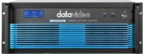
The front panel provides one power button and two USB 3.0 interfaces. Moreover, it can show the main unit's internal temperature and running time.
It is recommended to position the workstation horizontally so as to ensure air flows reaching the front and the back panels. Fans providing appropriate system cooling are located behind the panels. The workstation case is designed to be mounted on a server rack and occupies a 4U space.
Back Panel
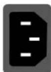
Power Supply Socket
Depending on the shipment destination and the user location, a power supply cord with a suitable plug will be supplied
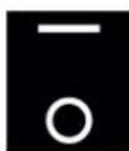
Power On/Off Switch
Switches power On/Off
0-OFF 1-ON
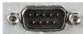
RS-232 Connection
The rear panel contains the RS-232 connection for operation with an external Datavideo RMC-280 control panel.
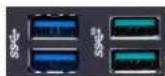
USB 3.x Type A Port
The rear panel provides you six USB 3.x Type A ports.
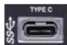
USB 3.x Type C Port
The rear panel provides you two USB 3.x Type C ports.
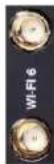
Wi-Fi 6 SMA Interface
It is used for connecting external Wi-Fi 6 antennas.
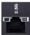
LAN (RJ-45) Port
Connection of the workstation to a computer network
LINE OUT Interface
It allows you to connect a headset or a speaker for monitoring.
Input/Output Card Options
With both display and virtu SDI cards installed, it is thus possible to achieve different combinations of views on the monitors. For more information, please refer to Configuration - Layout section.
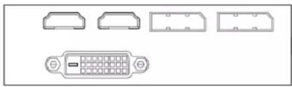
Display Card
natural_image
Technical line drawing of a D-sub connector with four mounting brackets and a central port (no text or symbols)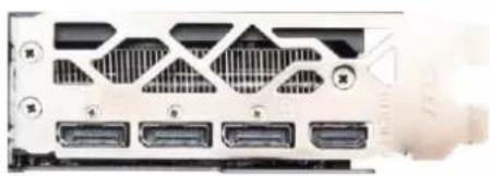
natural_image
Front view of a computer drive chassis showing ports and ventilation slots (no text or symbols visible)The interface of the Display Card is vary according to the real status of the TVS-2000A. (or it can be tracked by the serial No. of the TVS-2000A). There are two different versions which are shown as following section.
A: The display card provides one DVI-D port, two HDMI ports and two DisplayPort.
B: The display card provides one HDMI port and three DisplayPorts.
Note:
- It is recommended to connect production window (Monitor 1) to HDMI port.
- When using TVS series products, please remember to use the output interface which is located on the display card.
TVS-2000A SDI Card (Blue)

TVS-2000A SDI card allows connection of two SDI input/output pairs, a mini phone jack for audio input and a tally output to the TVS-2000A.
Note: Please connect any SDI cameras to use the TVS-2000A as a trackless Virtual Studio System.
Tracking Camera Control Card (Purple)

Camera Control card allows connection of two PTC-150 cameras to the TVS-2000A via RJ-45 ports such that they can also be controlled on the RMC-280 Virtual Studio Remote Control Unit.
Note: Please connect PTC-150 HDMI cameras to use the TVS-2000A as a tracking Virtual Studio System. See Section 4.11 Tracking Cameras to find out how you can set up tracking cameras for your TVS-2000A System. If the two connected PTC-150 cameras are set in tracking mode, the remaining V/Cs (Virtual Cameras) will be locked and can not be used by users.
Virtu AUX Card (Green)

The Virtu AUX Card provides an extra connection of HDMI input/output pair and a mini phone jack for audio input.
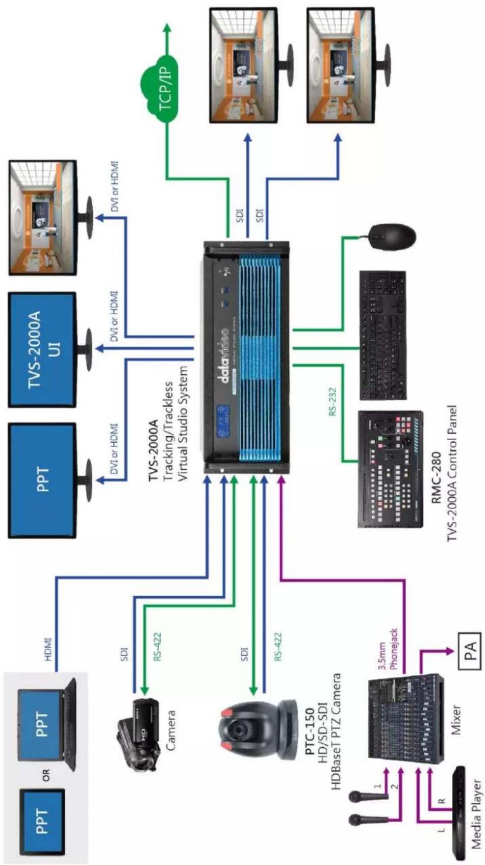
2.3 System Diagram
flowchart
graph TD
    A["Media Player"] -->|1 2| B["Mixer"]
    B -->|L R| C["3.5mm Phonejack"]
    C --> D["PA"]
    D --> E["RMC-280 TVS-2000A Control Panel"]
    E --> F["PSD"]
    F --> G["PTC-150 HD/SD-SDI HDBaseT PTZ Camera"]
    G --> H["Camera"]
    H --> I["HDMI"]
    I --> J["TVS-2000A Tracking/Trackless Virtual Studio System"]
    J --> K["DVI or HDMI"]
    K --> L["PPT"]
    L --> M["TVS-2000A UI"]
    M --> N["DVI or HDMI"]
    N --> O["TCP/IP"]
    O --> P["Computer"]
    style A fill:#f9f,stroke:#333
    style B fill:#ccf,stroke:#333
    style C fill:#cfc,stroke:#333
    style D fill:#fcc,stroke:#333
    style E fill:#cff,stroke:#333
    style F fill:#ffc,stroke:#333
    style G fill:#cfc,stroke:#333
    style H fill:#fcc,stroke:#333
    style I fill:#fff,stroke:#333
    style J fill:#fff,stroke:#333
    style K fill:#fff,stroke:#333
    style L fill:#fff,stroke:#333
    style M fill:#fff,stroke:#333
    style N fill:#fff,stroke:#333
    style O fill:#fff,stroke:#333
2.4 RMC-280 Remote Controller
The RMC-280 is a cost effective remote controller designed specifically for the TVS-2000A Virtual Studio System. The RMC-280 interfaces with the TVS-2000A Virtual Studio System via an RS-232 interface. The RMC-280 gives the user switcher-style control of the TVS-2000A Virtual Studio System. There are several effects that the user can also control on the RMC-280, such as downstream keyers (DSK) and transition effects. In addition, the T-Bar gives the user the convenience to perform transitions between Preview (PVW) and Program (PGM).
The RMC-280 has also been equipped with 10 function keys, which provide the user with the flexibility of manually assigning functions related to audio features, downstream keyer, delay, media player functions and output effects to the 10 keys.
The features are summarized as follows:
- A switcher style keyboard for direct TVS-2000A operation
- Clear key definitions
- Ten user-defined function keys, F1 to F10 and each of these function keys can be:
| Audio | DSK | General | Media | Output | V/C |
| Capture: Mute Capture: Volume Input: Mute Input: Solo Input: Volume Output: Mute Output: Volume Streaming: Mute Streaming: Volume | Set Position Set Preview Set Rotation Set Scale Set Source Transition Cut Transition Fade | Delay | Auto Play Loop Play Pause Play Select Stop | Select Preview Select Program Transition Cross-Dissolve Transition Fade to Black Transition Take | Studio: Load Studio: Select Camera Studio: Set Bus A Source Studio: Set Bus B Source Studio: Set Bus C Source |
- Program/Preset Rows with buttons allowing the user to switch between CAM 1, CAM 2, AUX, V/C 1, V/C 2, V/C 3, V/C 4, Media 1, Media 2, Still 1 and Still 2
- Ten custom-set phase buttons for virtual camera lens zoom in/out
- Linear and Curved buttons for respective camera movements.
- T-Bar can be operated in one way or two way mode
• TAKE button to switch between PVW and PGM views - FTB button fades the PGM view to a black screen
- CROSS DISSOLVE button applies cross-dissolve transition effect to switching between PGM and PVW views
- Two downstream keyers (DSK) with two corresponding knobs for assignment of DSK sources
- CUT and AUTO TRANS buttons transition DSKs between PGM and PVW views
• STM button starts live video program streaming
• Capture function (CAP Button) records the live video program - Still Grab function (GRAB Button) captures the instantaneous video image
• RS-232 interface for communication between RMC-280 and TVS-2000A - 12V DC input making the unit ideal for studio applications
- Bright LED lighting
Control Panel Overview
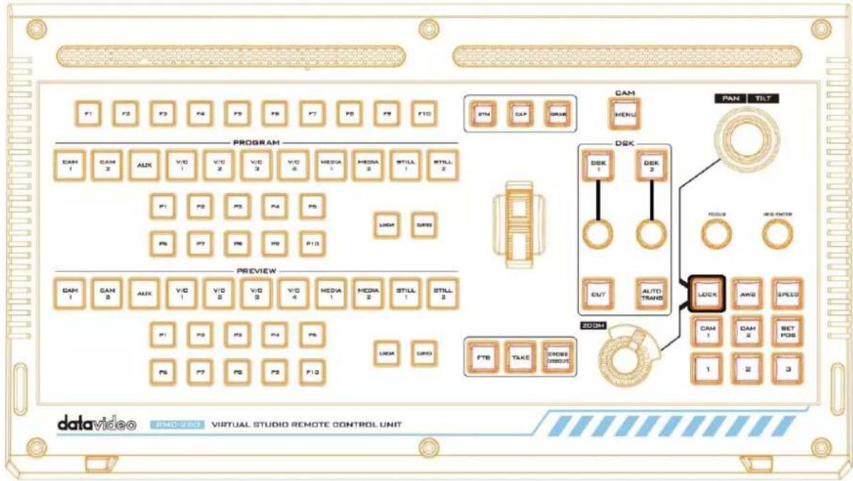
| TVS-2000A Virtual Studio Control Panel | |||
| F1-F10 | Function Keys F1 – F10 | Curved | Curved camera movement |
| CAM 1 | Camera 1 view | P1-P10 | Selection of position |
| CAM 2 | Camera 2 view | FTB | Fade PGM to Black |
| AUX | AUX view | Take | Switch between PVW and PGM |
| V/C 1 | V/C 1 view selection | Cross Dissolve | Cross dissolve transition effect |
| V/C 2 | V/C 2 view selection | Rolling Wheel | Manual Transition |
| V/C 3 | V/C 3 view selection | STM | Program Streaming |
| V/C 4 | V/C 4 view selection | CAP | Video Recording |
| Media 1 | Media 1 Video | Grab | Still Picture Grab |
| Media 2 | Media 2 Video | DSK 1 | DSK 1 and source assignment knob |
| Still 1 | Still Picture 1 | DSK 2 | DSK 2 and source assignment knob |
| Still 2 | Still Picture 2 | CUT | Placement of DSK on Program |
| Linear | Linear camera movement | AUTO TRANS | Auto transition of the DSK to the program view. |
| PTC-150 PTZ Camera Control Panel | |||
| Joystick | Camera panning and tilting | AWB | Automatic white balance |
| MENU | Opens the camera menu | Speed | Enable lens movement speed setting |
| FOCUS Knob | Camera focus adjustment | SET POS | Save current position into Lens position 1 / 2 / 3 |
| IRIS Knob | Camera iris adjustment While in the camera menu, pressing the Knob selects or confirms a selection. | CAM 1 | Selection of Camera 1 |
| Zoom Knob | Camera zoom adjustment | CAM 2 | Selection of Camera 2 |
| LOCK | Lock and Unlock PAN/TILT joystick and ZOOM knob | 1 / 2 / 3 | Lens positions 1 / 2 / 3 |
Main Unit - Rear Panel
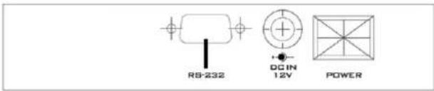
RS-232: RS-232 Communication Interface for connecting to the TVS-2000A machine.
DC 12V: 12V DC Power Input
Power: ON/OFF Switch
Program and Preset rows
The Program row of buttons is for control of the program output; this is the live output. You can switch or CUT from one video source to another directly on the Program row. You will see the PGM output changes as you press different keys along this top row of buttons.
The Preset row of buttons is for control of the Preview window. The Preset row sets the next transitioned program by pressing the corresponding key to select the source.

Preview and Program Switching

TAKE
This performs switching from the current program source to the selected preset source.

Cross-Dissolve
This performs a cross-dissolve switch from the current program source to the selected preset source.
FTB
Fade To Black, this button fades the current video program source to black. When pressed again it acts in reverse from complete black to the currently selected program video source.
natural_image
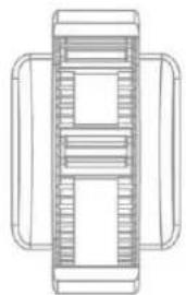
Top-down schematic of a mechanical or architectural component with no visible text or symbolsRolling Wheel (T-Bar)
This performs a manually controlled transition from the current program source to the selected preset source. When the rolling wheel has travelled as far as it can go, the transition between sources is complete.
Downstream Keyers
DSK 1/2
Pressing DSK 1/2 places logo or animations on the program view. Before placing the DSK on the program view, make sure it is correct on the PVW screen first.
Control Knob
Assigns a source to DSK 1/2 from a selection of camera, video files, and pictures
Cut
This cuts from the current key source to the selected key source. Transition effect is not used.

AUTO TRANS
This performs an auto transition switch from the current key source to the selected key source.
Function Keys


F1-F10
Ten user-defined function keys; please refer to the RMC-280 Function Keys section for more details
Stream
Start streaming the live video program to the Internet
Capture
Record the current live video program and save automatically to the hard disk.
Still/Grab
Capture a frame of video and save automatically to the hard disk.
P1 - P10
P1 to P10 buttons allow the user to select a particular position of a Virtual Camera (V/C).

Linear and Curved
In linear mode, the Virtual Camera moves between phases in a linear fashion.
In curved mode, the Virtual Camera moves between phases in an arc like path.
PTZ Camera Control
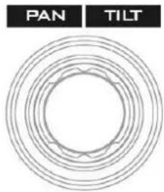
Joystick
Move the joystick sideways to PAN the camera lens. To TILT the camera lens, move the joystick up and down.
natural_image
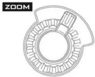
Technical line drawing of a mechanical component with concentric gears and a central shaft (no text or symbols)ZOOM Wheel
Move the zoom wheel clockwise and counter-clockwise to ZOOM IN/OUT the camera lens.
LOCK
Once the LOCK button is enabled, the joystick and ZOOM wheel will be locked, i.e. the user will not be able to adjust the PTZ settings using the joystick and the ZOOM wheel. To unlock, simple press the LOCK button again.
FOCUS Knob
Rotate the FOCUS knob clockwise and counter-clockwise to adjust the camera focus.
IRIS/ENTER
IRIS/ENTER Knob
IRIS: Rotate the IRIS knob clockwise and counter-clockwise to adjust the camera iris.
ENTER: While in the camera menu, pressing the Knob selects or confirms a selection.
AUTO White Balance
Pressing the AWB will automatically white balance the camera.

Speed
Press the SPEED button to set camera lens movement speed.
- Low Speed: Press once to turn the button white.
• Medium Speed: Press twice to turn the button pink.
• High Speed: Press three times to turn the button red.
CAM 1/2
Press CAM 1 button to select camera 1 and CAM 2 to select camera 2. Only one camera can be selected at a time.
Camera Lens Positions
- Press the SET POS button to enable "SAVE POSITION" function.
- Pressing button "1" saves current position into Lens position 1.
- Pressing button "2" saves current position into Lens position 2.
- Pressing button "3" saves current position into Lens position 3.
Note: To recall a stored position, simply press button 1, 2 or 3.
Keyboard Backlight
The RMC-280 allows the user to manually adjust the keyboard backlight. The steps are outlined as follows:
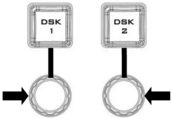
- To enter the keyboard brightness adjustment mode, press the two knobs (indicated by the arrows in the diagram below) below the respective DSK 1/2 buttons at the same time.
flowchart
graph TD
    A["DSK 1"] --> B["O"]
    C["DSK 2"] --> D["O"]
    B --> E["Arrow Right"]
    D --> F["Arrow Left"]
- Once in the keyboard brightness adjustment mode, all keyboard buttons will be illuminated white except the CAM MENU button blinking red.
- Rotate the left knob right to enhance and left to dim
- To exit, press the two knobs at the same time again.
RMC-280 Calibration Process
- Turn ON the machine and you will see most buttons illuminated white and a few illuminated red.
- To start the calibration, you have to press and hold the FOCUS and IRIS knobs at the same time first and then press the CAP button to enter the machine into the calibration mode.
- When the machine is in the calibration mode, you will see CAP and CAM MENU buttons blinking red and the F1-F4 buttons illuminate to indicate the calibration progress.
- Calibration of the idle position of T-Bar and Joystick is done automatically by the machine first and when it's done, the F1 button illuminates white with the rest illuminated red.
- The second step is to calibrate the T-Bar alone by moving it from top to bottom position a few times. The F2 button illuminates white (F1 button stays white) with F3 and F4 buttons illuminated red, the T-Bar calibration is complete.
- At the third step, calibrate the joystick by moving it from left to right and top to bottom or rotating. When the F3 button illuminates white (F1 and F2 buttons stay white), the joystick calibration is complete.
- Lastly the ZOOM calibration involves moving the ZOOM knob from right to left a few times. As the calibration is complete, all buttons will be OFF and the RMC-280 is ready to use.
2.5 How to Calibrate the PTC-150 Camera Position for Your TVS-2000A System
After finishing the basic system setup, please follow the steps below to optimize the visual effect of the TVS-2000A's tracking function.
Step 1: Make sure the tripod is placed on a flat surface and then mount the PTC-150 camera on the tripod. Focus the camera on the center of the frame.
Step 2: Reset "Pan, Tilt, Zoom" of PTC-150 to factory default. Please select 7: Reset P/T/Z → Yes on the PTC-150's main menu.
- Open the camera's main menu.
![[MAIN MENU] 1: CAMERA SET (NORMAL) 2: MEMORY 3: VIDEO OUTPUT 4: REMOTE CONTROL 5: SYSTEM 6: CAMERA SET (ADVANCE) 7: RESET P/T/Z 8: ESCAPE](/content/2026/05/998455/images/9ece23a3533847f1cc684b5ad496c9d464e549dc6690779028c9bb25beb65d22.jpg)
- Move down the menu and select item 7 Reset P/T/Z.
![[MAIN MENU] 1: CAMERA SET (NORMAL) 2: MEMORY 3: VIDEO OUTPUT 4: REMOTE CONTROL 5: SYSTEM 6: CAMERA SET (ADVANCE) 7: RESET P/T/Z 8: ESCAPE](/content/2026/05/998455/images/adf27660cf3e7e48e0c8ebf9d490203e09574ce19390f5c654f1617f01706c85.jpg)
- Once in option 7, select YES to reset PAN, TILT and ZOOM values to factory defaults.
![[MAIN MENU ] 7:RESET P/T/Z:YES](/content/2026/05/998455/images/411cbccea3f782fc394b37c6d287487ccfae0cbcf713f3ea4825ca2331471ba5.jpg)
Step 3: Make sure the PTC-150 camera is positioned at a perfect horizontal line level. If NOT, please open the main menu of the PTC-150 camera and select 5: System → 2: Set Motor → 6: Tilt Offset ADJ. to fine tune the camera's vertical position to the perfect horizontal line level.
- Open the camera's main menu and select the "System" option.
![[MAIN MENU] 1: CAMERA SET (NORMAL) 2: MEMORY 3: VIDEO OUTPUT 4: REMOTE CONTROL 5: SYSTEM 6: CAMERA SET (ADVANCE) 7: RESET P/T/Z 8: ESCAPE](/content/2026/05/998455/images/6afc2c86d9ab99d0cc414f1a0f101e58ce07860b05183f17800e62616bf082d2.jpg)
- Select "SET MOTOR."
![[SYSTEM] 1:DISPLAY 2:SET MOTOR 3:TALLY LIGHT: RED/GREEN 4:RESET ALL 5:UPDATE SOFTWARE 6:ESCAPE](/content/2026/05/998455/images/d58a2f1958377dc8cd8e803a08607dc11b2e750d6ae2a41b46ab8988ca87c221.jpg)
- Fine tune the camera position in the "TILT OFFSET ADJ." option.
![[SET MOTOR] 1:P/T ACCELERATION: MIDDLE 2:P/T SPEED:x2,SURVEILLANCE 3:PAN TORQUE ADJ.: +2 4:TILT TORQUE ADJ.: +2 5:PAN OFFSET ADJ.: +0.0 6:TIL OFFSET ADJ.: +5.4 7:ESCAPE](/content/2026/05/998455/images/8740a60da151f0f6eaf04b5bd3bbeac5230255df0b022a8cbf9edf4d85982ea1.jpg)
Step 4: Measure the height between the PTC-150 camera lens center to the ground in centimeters.
Step 5: Measure the distance between the PTC-150 camera lens center to the object shot in centimeters.
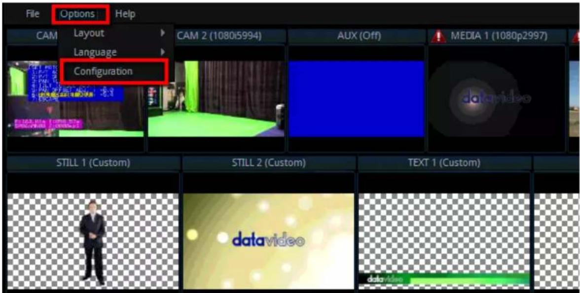
Step 6: Set the PTC-150 to Tracking Mode on the TVS-2000A user interface by selecting TVS-2000A Configuration Window / Tracking tab / CAM 1 (SDI IN 1) / Camera Port: CAM CTRL 1 / Tracking: V/C 1
- On the tool bar, select "Options" and then click "Configuration."
- Click the "Tracking" tab.
TVS-2000 Configuration
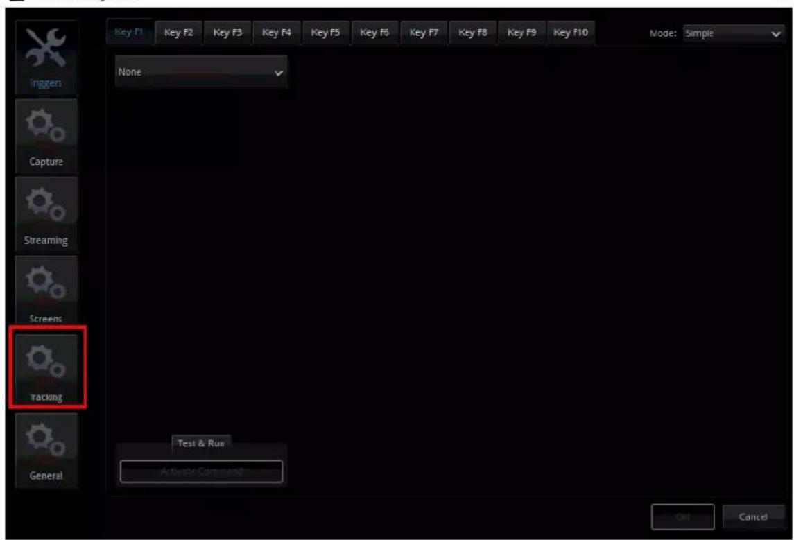
- On the CAM 1 (SDI IN 1) pane, set the Control Port to CAM CTRL 1 and Tracking to V/C 1.
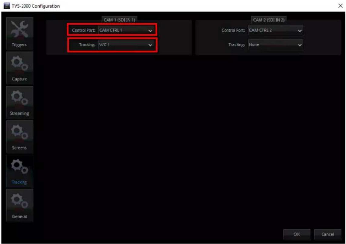
Step 7: At the bottom left of the Production User Interface, click V/C1 tab and enter "Camera Setup." At the top right corner of the Camera Setup screen, on the Position coordinates pane, enter the previously measured height and distance into the Y and Z fields respectively and then close the window.
- Click the Camera Setup button to open the Camera Setup window.
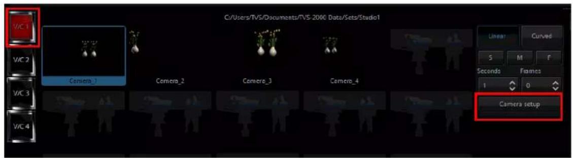
- Enter the previously measured height and distance into the Y and Z fields respectively
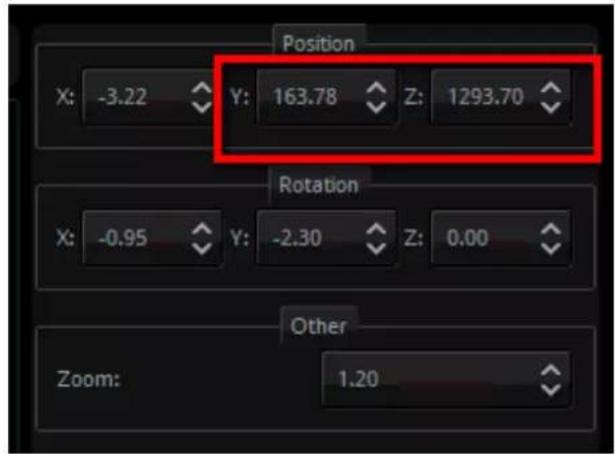
Step 8: At this point, you have done calibrating the PTC-150 camera position for the TVS-2000A system and you may start using it as you wish.
Note: If the two connected PTC-150 cameras are set in tracking mode, the remaining V/Cs (Virtual Cameras) will be locked and can not be used by users.
Chapter 3 Starting TVS-2000A Software
- Connect power cord, keyboard, mouse, and the RMC-280 to the TVS-2000A.
- Connect one or multiple monitors to TVS-2000A via HDMI, DVI and Display Port.
- Press the power button to boot the TVS-2000A hardware system. Power button is located on the right of the red reset button; please refer to the Connections Section for the appearance of the power button.
- Important: Please ignore everything during the system boot-up process, which can take up to approximately one minute, and you will be automatically directed to the TVS-2000A start-up page.
- On the start-up page, seven options are available for the user to choose:
a. Production live
b. STILL TEXT edit
c. TVS News link
d. VIRTUALSET shop
e. SHUTDOWN
f. Configuration
with details of which outlined in the subsections that follow.
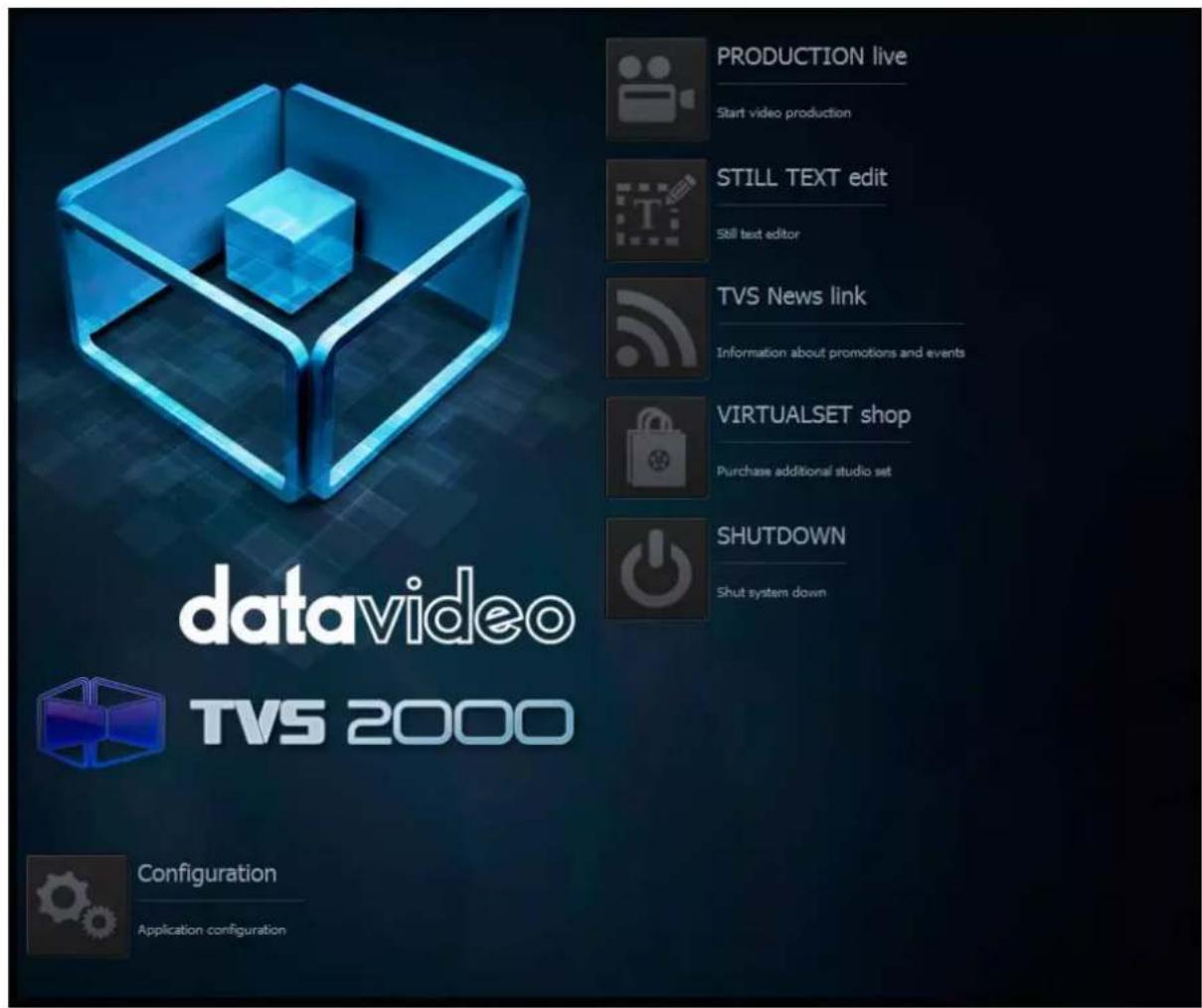
Start-up Screen
3.1 Production Live
Start a new production by first selecting an appropriate video format. Supported Video formats are:
• 1080i60 / 59.94 / 50,
- 720p60 / 59.94 / 50
• 1080p60 / 59.94 / 50 / 30 / 29.97 / 25
Click "Start Production" button to start a new production. The user is also allowed to load previously saved production. Choose a saved session from the pull-down menu as shown below and click the "Load Session" button to load previously saved production. You can also
browse the hard drive to load previously saved sessions by clicking on the button

3.2 Still Text Edit
The user can also open still text editor from start-up screen. Select a proper resolution first from the pull-down menu and click the "Start Editor" button to open the still text editor. The "Start editor with recent Still" section allows the user to open and edit previously saved
files by either selecting from a pull-down menu or browsing the hard drive.
3.3 TVS News link
The TVS News link allows Datavideo to publish updated information to the user. The information can be in the form of blog entries, news headlines, audio or video.
3.4 VIRTUALSET Shop
If the user would like to expedite production and avoid the hassles of creating their own virtual background, simply visit the VIRTUALSET shop to download currently available studio sets by clicking on the "Open Web Browser" button.
3.5 Shutdown
To exit the startup panel, the user can simply click the "Close application" button or the "Shutdown system" button to shut down the system.
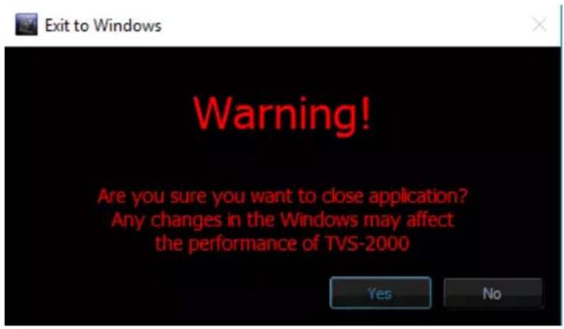
Note: A popup warning dialogue box will appear as shown below after you click the "Close application" button.
3.6 Configuration
Configuration offers the user four basic functions: language selection, firmware update, free virtualset download and system summary.
Language: A pull-down menu allowing the user to choose a desired language from English, Simplified Chinese, Traditional Chinese and Japanese.
Update button: When clicked, the system will search for firmware update.
About button: A pop-up window will appear, displaying information such as EULA, Version number, and Serial Number.
Chapter 4 Production Live Screen
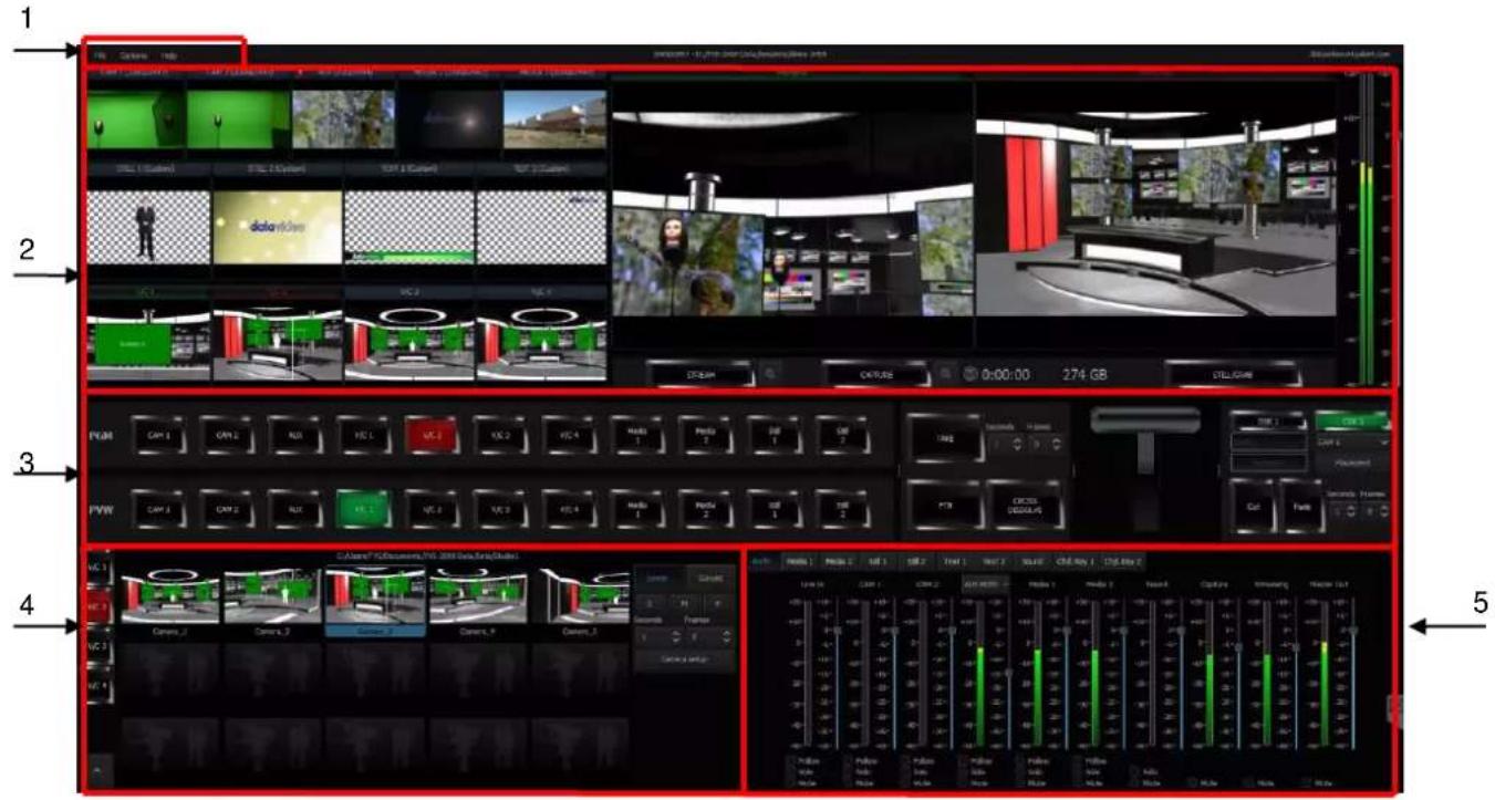
After entering the production live option, the production screen will appear as illustrated in the diagram below. The production screen can generally be divided into five areas:
- Tool Bar
- Multi-View Screens
- Switcher-like Buttons
- Scene Editing
- File Management
4.1 Tool Bar
There are three options on the tool bar: File, Options and Help.
File
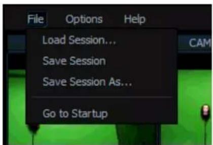
- Load Session: Opens previously saved production
• Save Session: Saves the current production - Save Session As: Saves the current production with a different name
- Go to Startup: Takes the user back to the startup screen
Options
In Options, you will be able to select the number of screens used, set the UI language and open the configuration window.
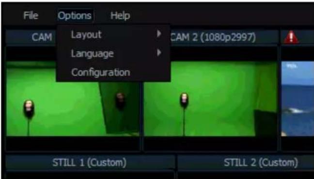
Layout
Screen adjustment where in this option the user is allowed to select the number of screens to be used.
- One Screen
- Two Screens (Production + Multiview)
- Two Screens (Production + Program)
- Two Screens (Production + Preview)
• Three Screens (Production + Multiview + Program)
• Three Screens (Production + Multiview + Preview)
Language
The user is allowed to select among three languages listed as follows:
- English
- Simplified Chinese
• Traditional Chinese - Polish
Configuration
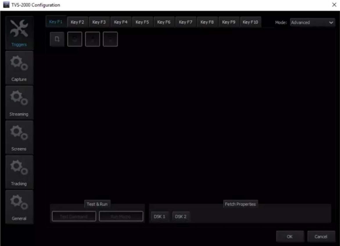
Clicking this option will open the window as shown below, where you will be allowed to:
- Define the function keys of the RMC-280 keyboard in Triggers.
- Configure the capture card settings in Capture.
- Enter the stream settings in Streaming.
- Select the appropriate screens in Screens.
- Enable the tracking feature of the PTC-150 camera in Tracking.
- Set other system setting options in General.
Help
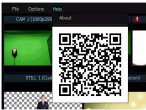
- About: Clicking About displays information such as EULA, Version number, and Serial Number
- QR Code: Scan the QR code to download the TVS-2000A User Manual
4.2 Multi-View Area
In the multi-view area, the user is able to view the camera source and other multiple multimedia file sources on the left-hand side of the area. There are two screens on the right-hand side: PREVIEW and PROGRAMME.
- PREVIEW – presentation of the next element prepared for broadcast
• PROGRAMME – presentation of the current programme broadcast (system output)
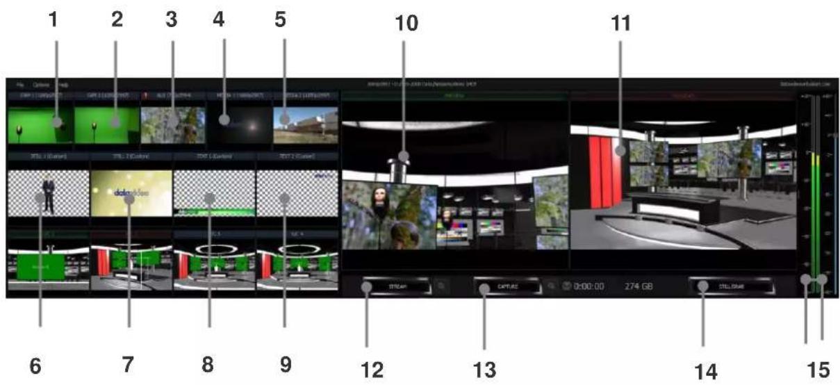
Details of each individual element are described in the table below.
| 1 | Cam 1 | SDI Camera preview window 1 |
| 2 | Cam 2 | SDI Camera preview window 2 |
| 3 | AUX | Additional camera or media player input or Powerpoint presentation input |
| 4 | Media 1 | Video clip 1 from hard disk drive |
| 5 | Media 2 | Video clip 2 from hard disk drive |
| 6 | Still 1 | Preview window for picture 1 |
| 7 | Still 2 | Preview window for picture 2 |
| 8 | Text 1 | Preview window for the still text source 1 |
| 9 | Text 2 | Preview window for the still text source 2 |
| 10 | Preview | Preview source window |
| 11 | Program | Program source window |
| 12 | Stream | Stream the program video to the Internet |
| 13 | Capture | Record the program video to PC's hard disk |
| 14 | Still / Grab | Capture still picture on the program screen |
| 15 | Audio Meters / Volume Control | Audio meters display the output audio signal strength & volume control adjusts the output audio signal strength |
4.3 Program and Preview Rows & Function Settings
The central part of the screen of Production Live is occupied by the Production Switcher. The Production Switcher panel consists of two rows of buttons and a block of executive buttons. It is used to send selected content on air and prepare the next material for broadcasting.

Program and Preview Rows are production switcher style buttons. The user is able to switch between different sources displayed on the Preview and Program screens by clicking on the corresponding buttons.
11-input Main Switcher
➢ 2 x CAM – Enables two camera sources and the chroma and luma keying functions can be applied to the signals on this channel.
➢ 1 x AUX – Additional camera or media player input or Powerpoint presentation input
➢ 4 x V/C – Four virtual camera inputs
- 2 x Media – Two video programs saved on local hard disk
2 x Stills – Two static pictures saved on local hard disk

The top row of buttons, PGM, indicates the image that is currently broadcast. The selected broadcast source button is illuminated in red.
The lower row of buttons, PVW, indicates the source of image to be broadcast next. The active button is illuminated in green. The material choice is seen in the PREVIEW window.
After editing and selecting the desired program source, the next step is to use function keys to stream the program, apply transition effect, place logo on the program view, add animation to the program and etc. Brief descriptions of function keys are outlined below.
Switching between Preview and Program Views
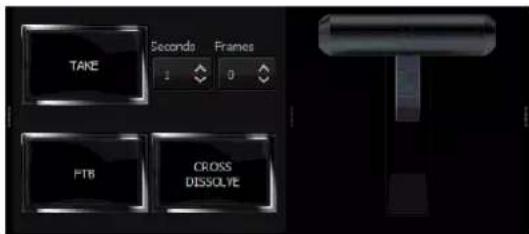
➢ TAKE: Click to switch between Program and Preview with a transition effect
FTB: A Fade-to-Black is the effect which fades the Program view gradually to black, or when a picture gradually appears on screen; click the button to apply the FTB effect to Program output
Cross Dissolve: A dissolve is a gradual transition from one image to another; click the button to apply the effect.
T-Bar: Shift up and down to switch between Preview and Program.
➢ Transition time will be based on Time and Frame presets in seconds.
Downstream Keys
Next to the 11-input main switcher is the downstream key (DSK) block. It can be used to add images or text to the broadcast signal. DSK signal may come from any virtual player that displays media (1 or 2), bitmaps (1 or 2), or text (1 or 2). It may also come from the camera inputs. For the DSK function to operate properly, the media provided to DSK must contain transparent areas. In this way, they will be overlaid on the main signal. Media without transparent areas is not recommended to be used in DSK as they would completely cover the broadcast image with their contents.
There are two DSK keys available for the user. Follow the following procedure to display DSK on the Program view:
- Switch on one of the DSK buttons;
- DSK button is illuminated in green;
- Select the source from the list below;
- The text is ready to be broadcast;
-
The text preview is shown in PREVIEW;
-
The Placement button can optionally be used for changing the size or position of the text on the Preview screen (Note: change of the text position is impossible if the text is already on air);
- The text can be put on air gradually (using the Fade button) or abruptly (using the Cut button) and disappears from the Preview Screen;
- The operation of the Fade and Cut buttons is independent of the Production Switcher TAKE button;
- If the text is on air, the colour of the DSK button changes to red;
• To remove the text from the air, click the Fade or Cut button once again; - When the text is taken off air, the DSK button colour returns to green and the text will now appear in PREVIEW screen again.
Text 1
Text 2
Media 1
Media 2
Still 1
Still 2
Camera 1
Camera 2
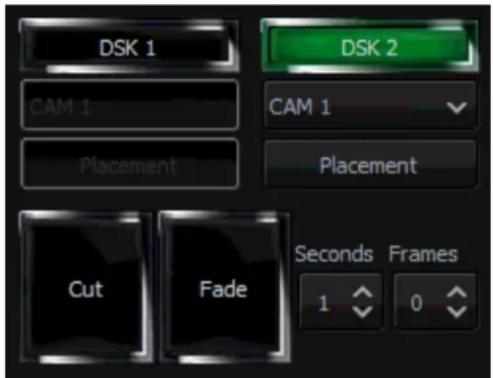
To configure position and size of the downstream key, click the placement button to open the configuration window.
After the DSK is properly configured, the next step is to place the key on the program view. Click CUT/Fade buttons to switch the key between Preview and Program screens. The two downstream keys are designed in such a way that the user is allowed to simultaneously place two downstream keys on the program view.
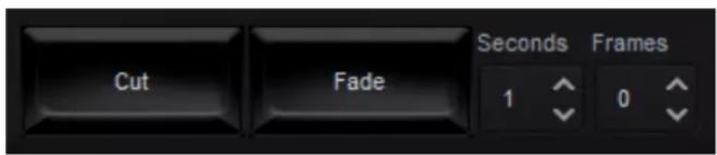
➢ Cut: Instantaneous switching between Preview and Program screens
Fade: Gradual switching between Preview and Program; fade time will be based on Time and Frame presets in seconds.
4.4 Scene Editing
In Scene Editing, each virtual camera (V/C) behaves like a real camera. In other words, selection of an V/C is like selecting a camera in a multi-camera environment. Each position corresponds to a virutal camera position (Camera_1, Camera_2, and etc). The user can switch between positions by clicking on position windows, which is similar to the “cut transition” effect on a switcher.
In the Scene Editing area, the user is allowed to perform advanced editing of up to a maximum of four virtual cameras (V/C1 – V/C4). In each of the V/C editing, there are fifteen positions available, allowing the user to zoom in to the talent with each position corresponding to a user-defined zoom distance. Please see the diagram below for diagrammatic illustration.
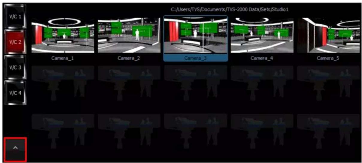
Click at the bottom left corner to open the virtual camera configuration panel for selecting raw materials.
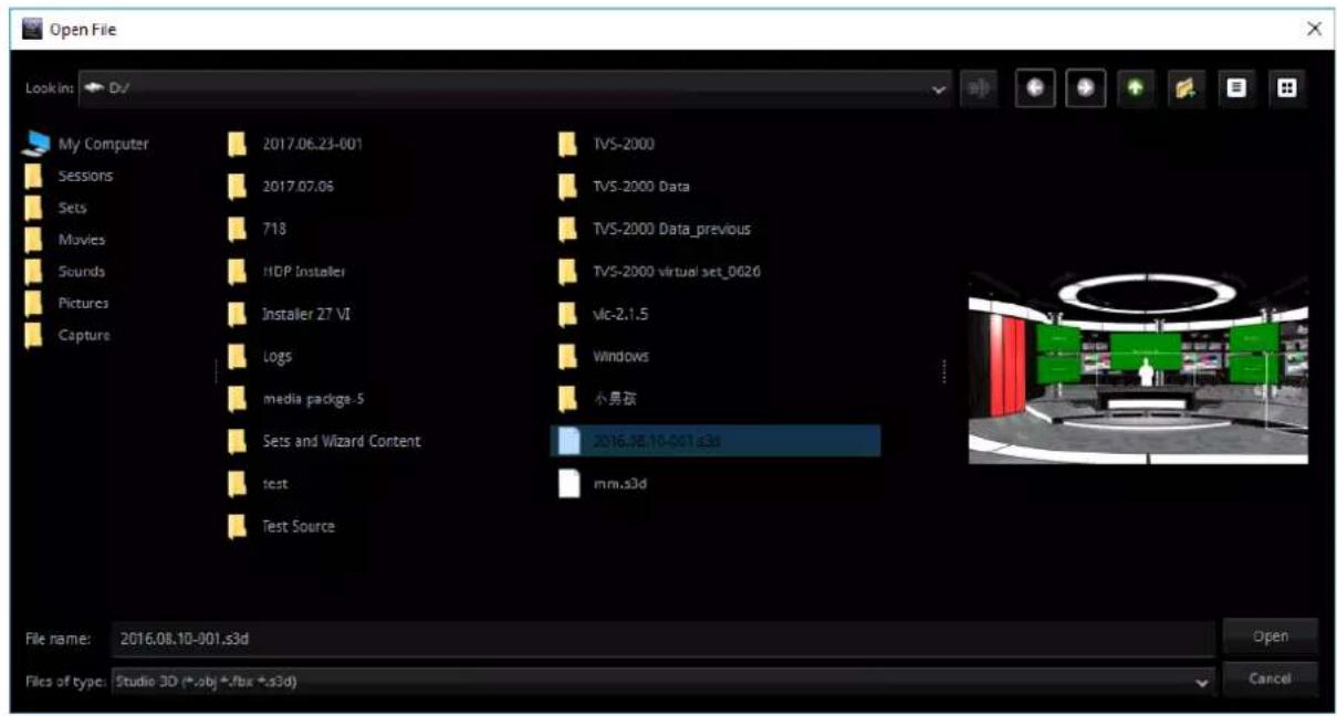
The user may import studio scene from the hard disk drive (HDD). Click the LOAD button to open a window that displays a list of directories containing studio files. Preview of the selected scene is available on the right of the directories listing window. Choose the desired s3d file to the selected V/C bin. Click the V/C 1-4 tabs to view the loaded virtual studios in Preview window of the Multi-View Area.
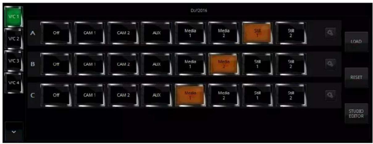
After loading the studio scene, the three rows of buttons allow the user to select talent material source and plasma TV material source. As depicted in the diagram above, Row A is for talent 1 material source selection and Row B is for talent 2 material source selection. Row C is for plasma TV material source selection. The sources can be live show from Camera 1 or 2, Media 1 or 2, Still 1 or 2, or even Black if necessary. The selected source button will be illuminated in amber.
Row A and Row B are usually talent images from CAM sources. The keying filter is overlaid on this source. The keying filter overlay removes the single-colour background on which the talent is shot (e.g. green). The third signal source, Row C, may be a video or a still image. It is usually displayed on a virtual screen, which is designed as part of the studio set. However, it all depends on the studio design. Signals can be used differently in every studio. Because of this, signals are denoted in a universal way, as A and B, in the studio configuration panel.
The Reset button resets the studio 3D cameras to default takes. To modify the studio scene, click the STUDIO EDITOR button to open the 3D Studio Editor. Please see Chapter 7 3D Studio Editor for instructions on how to edit the studio scene.
Camera Setup
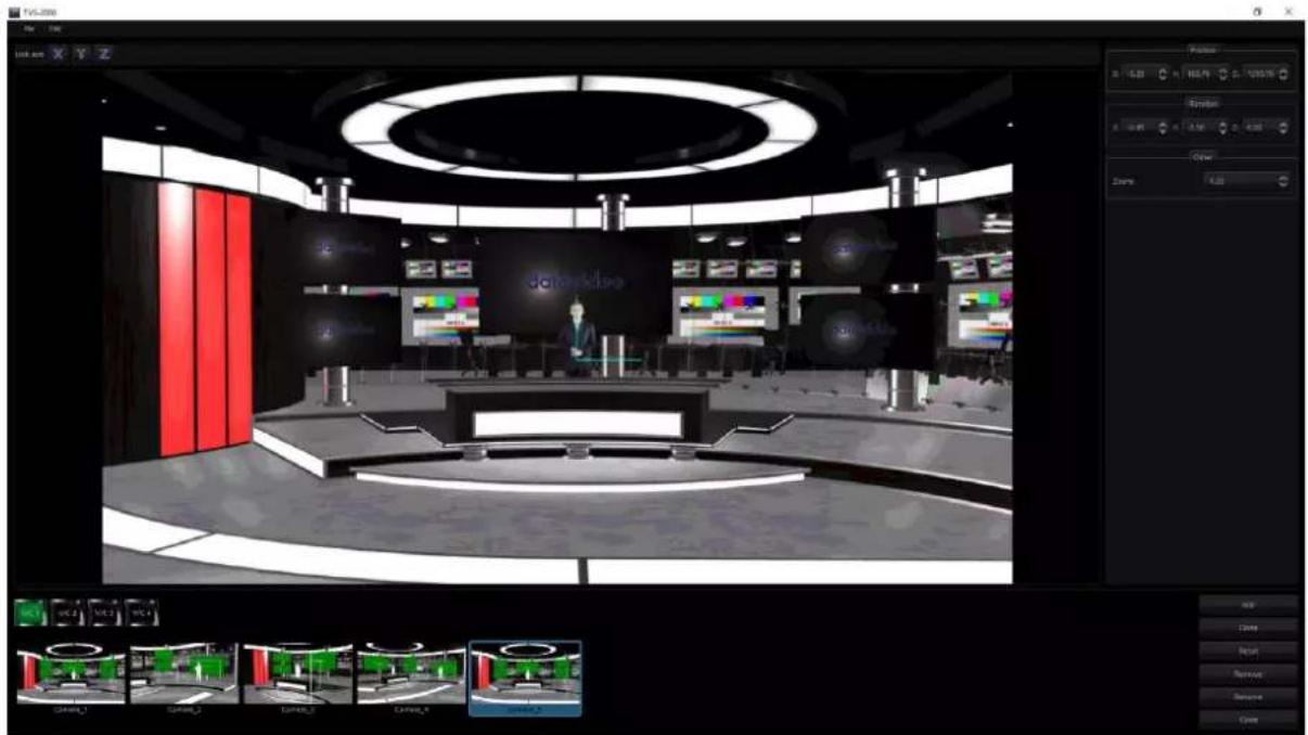
After selecting the talent and plasma TV material sources, the next step is to customize your program. Click the "Camera Setup" button to open the camera setup window as shown in the diagram below.
natural_image
3D studio scene with a large curved stage, red vertical bars, and multiple screens displaying colorful images (no readable text or symbols)The pane on the right of the camera setup window allows the user to adjust position, orientation and zoom settings of the scene. The respective parameters are described as follows.
Position
• X: Adjustment of the x-axis moves the scene horizontally.
- Y: Adjustment of the v-axis moves the scene vertically.
• Z: Adjustment of the z-axis moves the scene back and forth.
Rotation
• X: Rotation of the scene along the x-axis.
• Y: Rotation of the scene along the y-axis.
• Z: Rotates the scene sideways.
ZOOM
- Increase the value to ZOOM IN and decrease to ZOOM OUT.
At the bottom pane of the camera setup window, the user is allowed to select up to 15 camera takes for each V/C. The function of each button is described as follows.
- Add: Adds new camera
- Clone: Clones selected camera
- Reset: Resets selected camera settings
- Remove: Removes selected camera
- Rename: Renames selected camera
- Close: Close camera setup window
Linear and Curved Auto Play
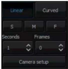
Auto Play generates the animated PTZ transition effect. After clicking the Linear or Curved button, the Auto Play function is enabled and the camera movement will be smooth and animated. The transition time is adjusted by controls located below the Linear and Curved buttons. The Time and Frame fields allow the user to adjust the transition time in seconds or frames. To make things easier, three default transition times between phases have been defined:
• S: Slow speed (5 seconds by default)
• M: Medium speed (3 seconds by default)
• F: Fast speed (1 second by default)
If the Auto Play button is turned off, the camera position is switched 'sharply' (cut effect without animation).
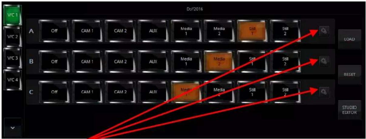
Finally, click on located on the right of the rows of Source A, Source B and Source C to open a configuration window that allows the user to adjust the size and position of the talent as well as the view on plasma TV. The settings are remembered by the program until a new view is loaded. To be remembered, they can be saved in the session file. The configuration window is shown below.
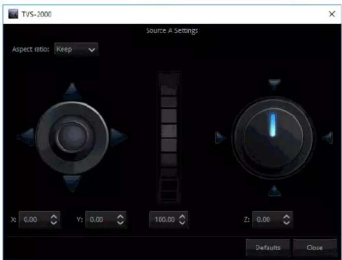
☐ Joystick: Talent positioning
☐ Center Roller: Talent scaling
☐ Adjustment Knob: Talent rotation
All settings of a studio (selected sources, source positions, camera phases) can be stored for later use by saving them in a session file. The settings saved in this way can be loaded by opening the session file upon starting the Production Live module.
4.5 File Management
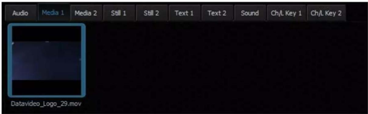
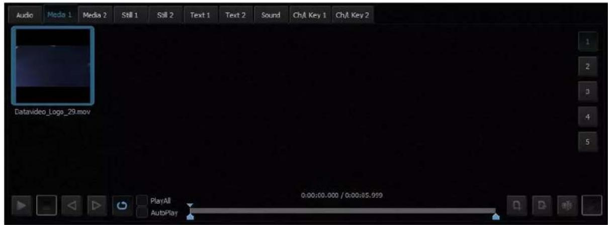
The TVS-2000A allows the user to apply videos and still images to the program window. The file management system is designed to serve this purpose by allowing the user to do all the preparation work before the broadcast. It is also known as Media Bin, which is divided into tabs as shown in the diagram below. Shortcuts to the media files are placed in the appropriate tabs. This facilitates the use of media during live production.
The bin has six tabs for files assigned to a given player. There are two tabs for video files (Media1, Media2), two for bitmaps (Still1, Still2), and for text (Text1, Text2). TVS-2000A supports the use of media in multiple formats. It has also integrated support for many codecs to play video files.
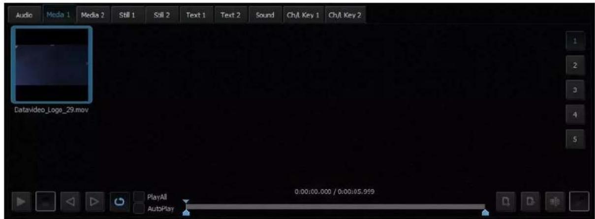
In each specific tab, the user can also divide the content (files) into five categories (maximum). This is done by means of sections (designated 1 to 5). The sections can be used to keep files in order, for specific activities.
The use of media requires two actions:
• the addition of a file to the bin;
- loading the medium into a virtual player.
For each file added to the Media Bin, an icon is automatically generated. This enables the preview of the file content. Within a given tab, icons can be sorted using drag and drop. For files with the alpha channel (with transparency), a preview is displayed showing transparency against a background of a gray and
white grid.
To add a file to the bin, a tab (or a subtab within a tab) has to be selected. After that, either click the D and file button or double click an empty space within the selected tab of the bin, and a typical file browsing window will be opened.
Next to the add file button, there is a file removal button. It removes the selected file from the bin. If the file being removed has already been loaded into a player, the user will be prompted for confirmation. After the removal of a file (media), the preview for the corresponding player shows a blue background.
Please note that no operations on files in the Media Bin change files on the hard disk. File removal or file name changes only affect shortcuts to the files on the tabs. It is also possible to add a file to the same tab or to different tabs multiple times. The user can also change the names of files (shortcuts) by clicking the file name change button next to the file removal button, and the same file can be used with different names.
To load the medium into a virtual player, double click the file with the mouse. The medium will be played (MEDIA1 or MEDIA2, STILL1 or STILL2, TEXT1 or TEXT2) and can be used directly in a live program.

Buttons in the lower part of the Media Bin are used to control the file played in the player. The available functions are: Play , Pause , Stop , and Loop (Loop is only default).
The playback progress bar, information on the video length and the current playback position are also shown. Right after being double clicked in the bin, a video is loaded into a virtual player and begins to be played in a loop. If the loop playback is switched off, the video will stop on the last frame. Pressing the Stop button causes playback to return to the first frame.
The Media Bin also has mark-in and mark-out features that allow the user to set a start point and an end point before playback of a video clip. The user can simply move the cursor on the playback progress bar and fine tune the cursor position frame by frame by clicking the forward and reverse buttons.
In addition, by checking the PlayAll option and enabling the loop feature, the user is allowing loop playback of the whole media folder. AutoPlay allows the virtual player to play the video clip upon entering the media folder.
NOTE: It is recommended that files should be added to the Media Bin only from a hard disk permanently connected to the workstation. If files from other media need to be used, they should be physically copied to the hard disk and only then added to the Media Bin.
Media 1/2 – As depicted in the diagram below, this is where the video files can be displayed. Click to browse the local hard disk for video files. The user is allowed to classify the selected video files into five categories. Navigate through the categories by clicking on buttons 1 to 5 located on the right of the file display area.
The formats and codecs supported for video files (for media added to the MEDIA1 and MEDIA2 tabs) are:
- MPEG4 and H.264
- MPEG-2 Smart Render Wrapper
- DVCPRO 25/50/HD
Still 1/2 – As depicted in the diagram below, this is where the still picture files can be displayed.
Click ☐ to browse the local hard disk for picture files. Again, the user can classify the selected picture files into five categories. Navigate through the categories by clicking on buttons 1 to 5 located on the right of the file display area.
The formats supported for bitmap files (for media added to the STILL1 and STILL2 tabs):
- JPG
- PNG (with transparency)
- BMP
To perform slideshow of still pictures, enable the "PlayAll" function and then click the Play button.
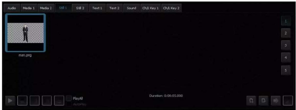
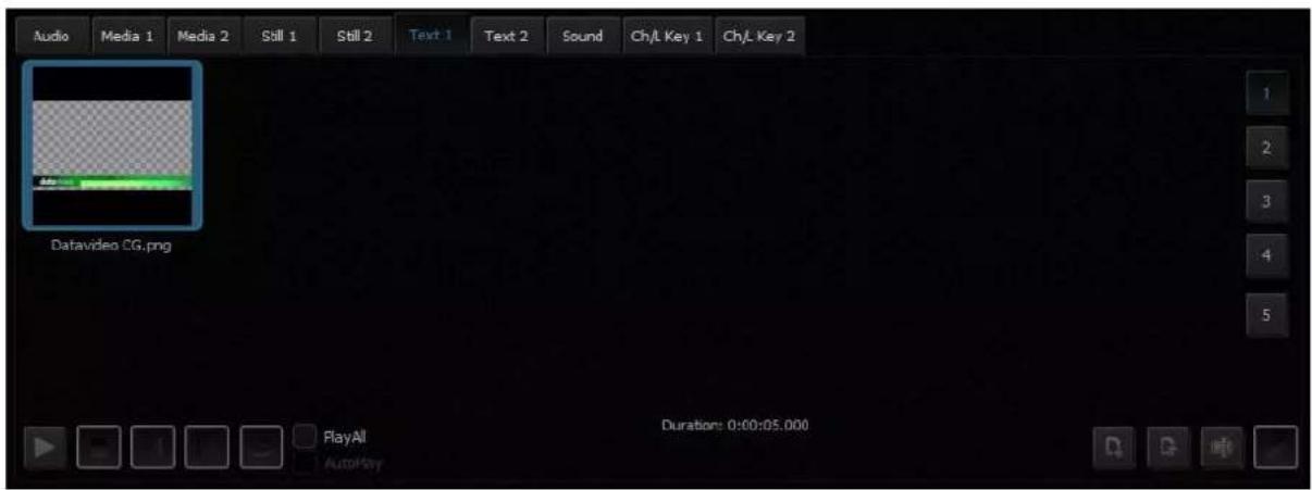
Text 1/2 – As depicted in the diagram below, this is where the still text files can be displayed. Click 📄 browse the local hard disk for still text files. Again, the user can classify the selected still text files into five categories. Navigate through the categories by clicking on buttons 1 to 5 located on the right of the file display area.
The formats supported for bitmap files (for media added to the TEXT1 and TEXT2 tabs) are:
- JPG
- PNG (with transparency)
- BMP
- TVS-2000A STILL (System's STILL TEXT edit module)
4.6 Triggers – RMC-280 Function Keys
The user is allowed to control the TVS-2000A with external keyboards such as the RMC-280 Remote Controller.
There are 10 user-defined function keys, F1 to F10, on RMC-280 Remote Controller. These function keys are configurable on the TVS-2000A system. Each of these function keys can be assigned of multiple functions selected from the table below:
| Audio | DSK | General | Media | Output | V/C |
| Capture: Mute Capture: Volume Input: Mute Input: Solo Input: Volume Output: Mute Output: Volume Streaming: Mute Streaming: Volume | Set Position Set Preview Set Rotation Set Scale Set Source Transition Cut Transition Fade | Delay | Auto Play Loop Play Pause Play Select Stop | Select Preview Select Program Transition Cross-Dissolve Transition Fade to Black Transition Take | Studio: Load Studio: Select Camera Studio: Set Bus A Source Studio: Set Bus B Source Studio: Set Bus C Source |
The user just needs to press the function key once to execute the selected functions according to the sequence in which the functions are selected.
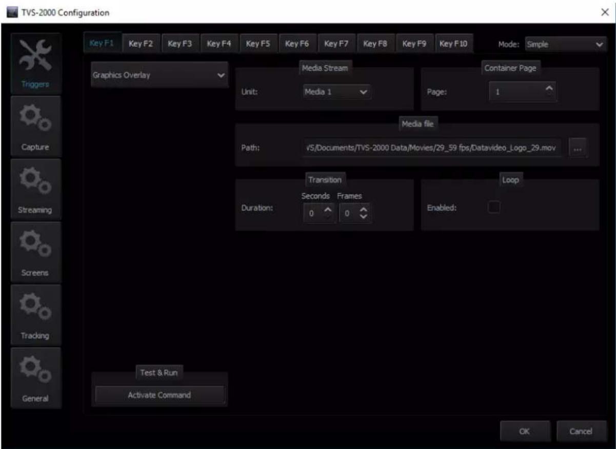
To assign specific multiple functions to these 10 function keys, open the TVS-2000A configuration window and click the "Triggers" button. Function key tabs can be found at the top of the configuration window. Click the Function Key tab that you would like to customize and in the example below, Key F1 is selected.
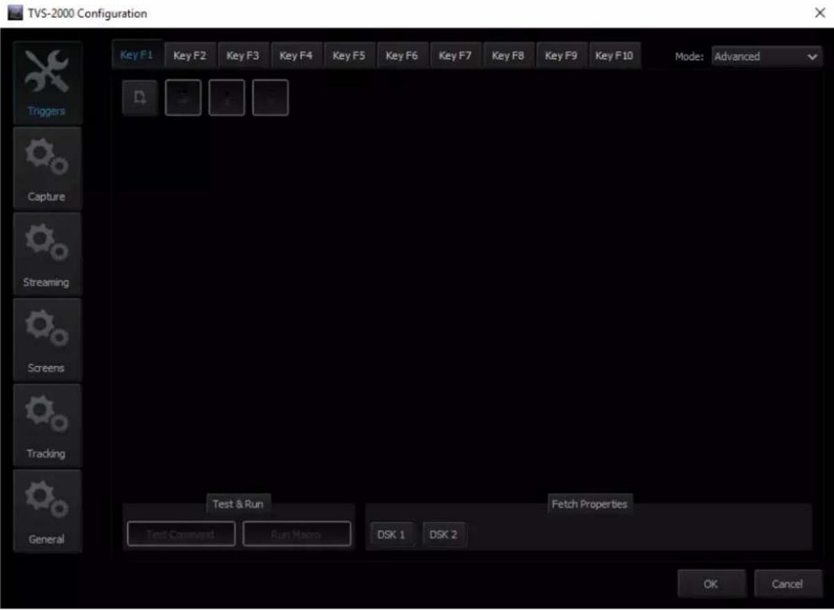
In general, two modes are available and they are "Simple" and "Advanced."
Advanced
In Advanced mode, the user is allowed to select all available functions in the above table. Furthermore, the execution sequence of the selected functions is customizable.
Select "Advanced" and click to open a command selection window shown below.
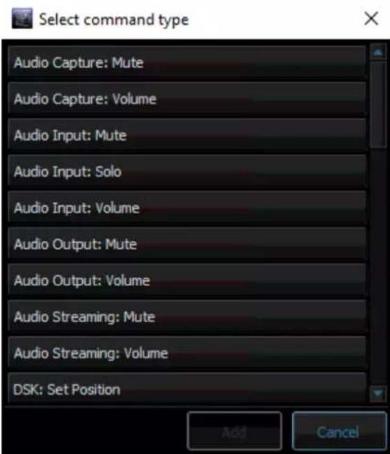
Select a function, for example, "Audio Capture: Mute" and then set the corresponding parameters. Click again to select the next function until all desired functions are selected.
After all the desired functions are selected, click the next key tab and repeat the above until all keys are assigned the functions that you desire.
Simple
If the user's selection is "Simple" Mode, a user interface will appear as shown in the diagram below. On the interface, the user is only given the Graphics Overlay function (Media Stream) to perform simple customization of the function key. After the function key is customized, pressing the RMC-280 function key button will play the media stream and again to reverse the media stream playback.
4.7 Monitor Configuration
The TVS-2000A operates on multiple input and output signals. To ensure better functionality for the preview of the signals, the user may connect additional monitors to the workstation. With a separate monitor, the preview can be larger than the one in Production Live.
Another monitor can be used for Multiview, which is a clear interface presenting the previews available in Production Live.
The following previews are available in Multiview:
- PREVIEW – presentation of the element chosen to be broadcast next;
• PROGRAM – presentation of the current signal (system output); - Previews of studio scene loaded into memory;
- Preview of all media loaded into virtual players;
- Camera preview (one or two, depending on system configuration).
A third monitor may, with suitable configuration, show a full-screen PREVIEW or PROGRAM view. The third monitor can also be used for the mirror output of the talent.
Hence, in order to allow the user to manage multiple monitors, a Monitor Configuration Interface as shown in the diagram below is built into the TVS-2000A. To open the interface, simply click "Configuration" on the tool bar, select "Configuration" option and then click "Screens" button.
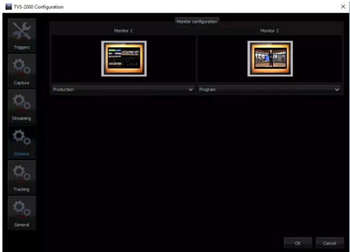
The user is thus able to shuffle monitor assignments by making selection of the desired display in the pull-down menu. In the example above, only two monitors are connected and one monitor is configured to display the production module and another one is configured to display the program view.
4.8 General Display and Audio Settings
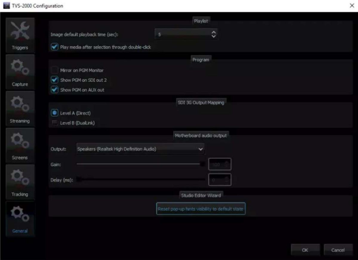
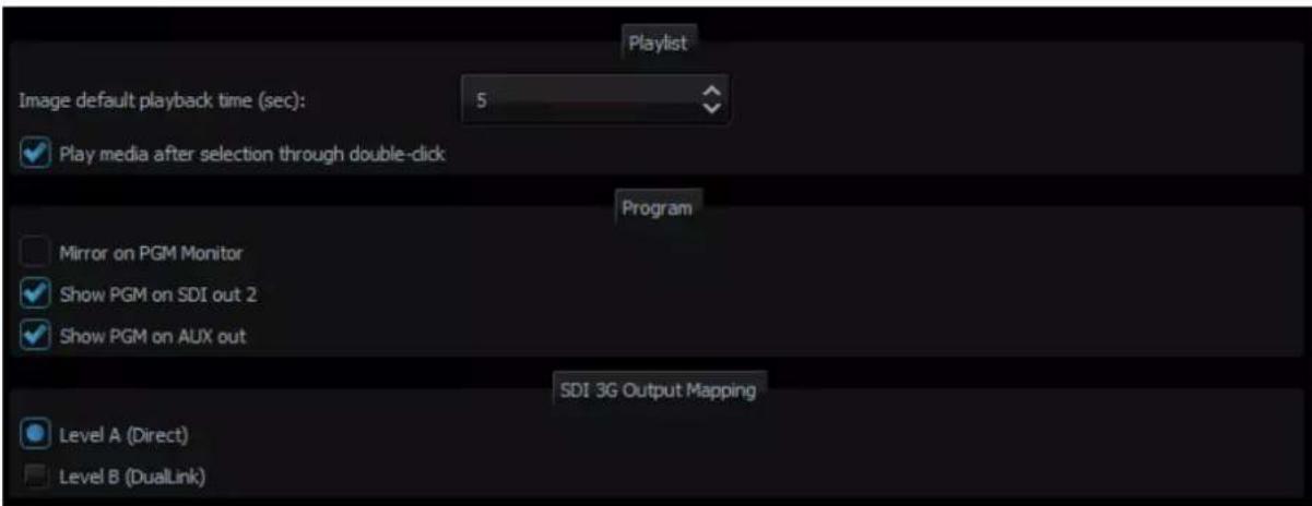
To configure additional display settings, click the General tab where the user will find two options, Image default playback time (sec) and Mirror on PGM Monitor as shown in the diagram below. By checking the option, "Image default playback time (sec)", the user will then be allowed to set the playback time for slide show of still images. Mirror on PGM Monitor, after enabled, will display a mirrored image of the Program View, i.e., the Program view image is flipped along the y-axis.
There are two SDI types (Type A and Type B) available on the TVS-2000A. Please note that most Datavideo products adopt type A.
In addition, the TVS-1200A is able to output PGM audio on the selected sound card. To hear the PGM audio, follow the steps outlined below to configure your system setup.
- Connect any sound playing device to the motherboard's audio output jack.
- Open the "Configuration" window and select the "General" tab.
- On the "Configuration" window, locate the Motherboard Audio Output section and select a sound card from the "OUTPUT" pulldown menu. The TVS system, by default, selects the Windows sound card. In the example above, we have selected the Realtek High Definition Audio.
- Click OK.
-
The PGM embedded audio should now be heard on the sound card's audio output. The user is allowed to mute or adjust the volume on the motherboard's Audio Manager Interface.
-
The selection will be remembered once the Motherboard Audio Output has been configured. In this way, after the audio cable is disconnected from the TVS system, the connection will be automatically re-established after the audio cable is plugged back in again.
Two other additional things can be configured in the Motherboard Audio Output section:
- Gain: The Gain sliding bar is used for audio volume adjustment, which is set to the maximum level by default.
- Delay: By sliding the Delay bar to the right you are adding delay to the audio line which synchronizes the audio to the video if the video display device (typical LCD TV) generates delay.
Note: A prompt window will be popped up upon connecting the audio cable to the motherboard's audio jack. We recommend disabling this prompt window. The screenshot below shows you where this auto popup dialog can be disabled.
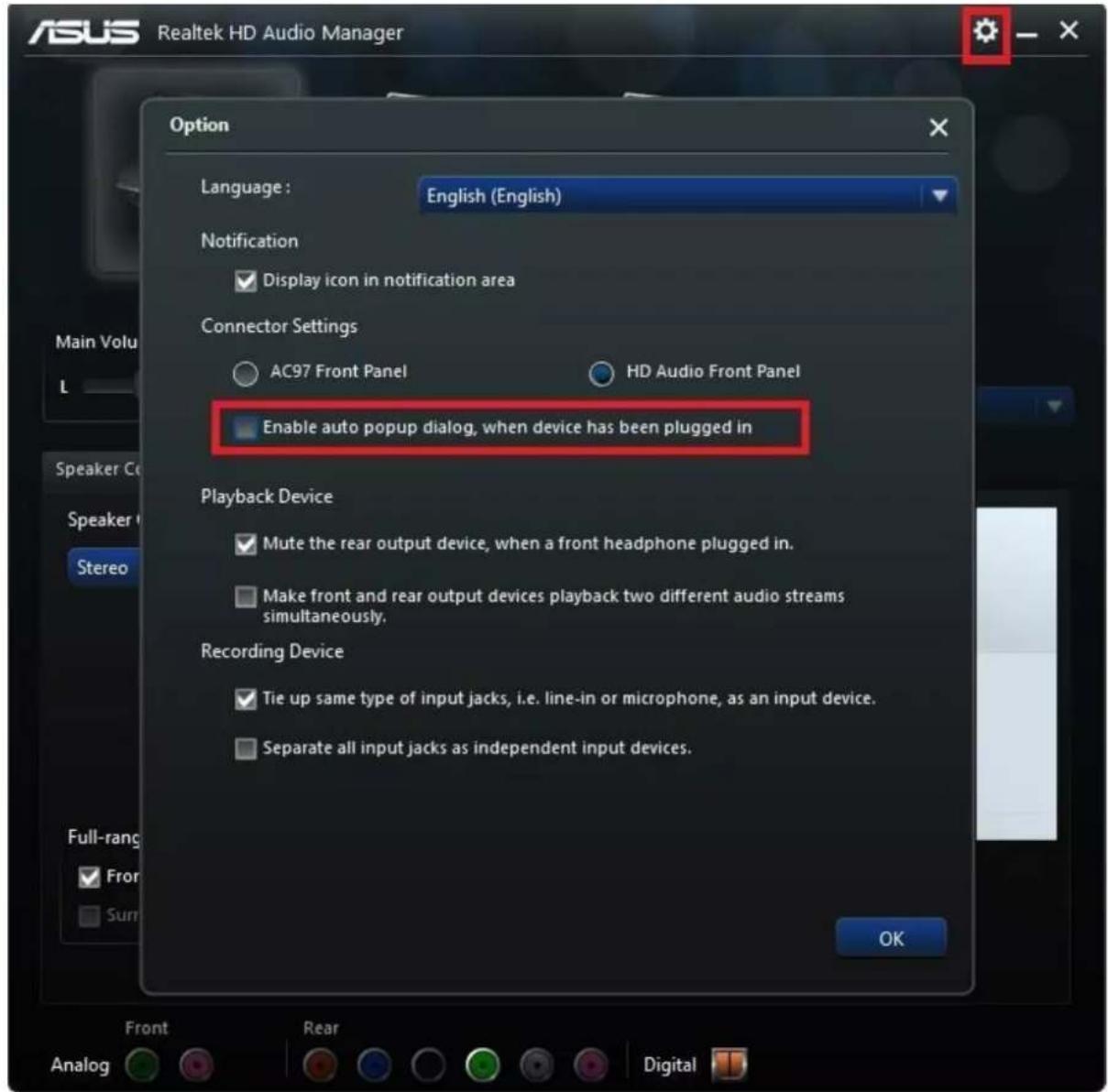
4.9 Motion Capture Specification
The TVS-2000A uses Intel® Quick Sync Video technology, which is a built-in feature in some of Intel processors. It allows hardware acceleration of video stream encoding. The TVS-2000A also supports capturing of system PGM output. This enables the use of the TVS-2000A as a video recorder and is usually used in live production. The file is created in the MP4 or MPEG2 format.

Supported encoding formats (CODEC) are:
H.264
MPEG-2
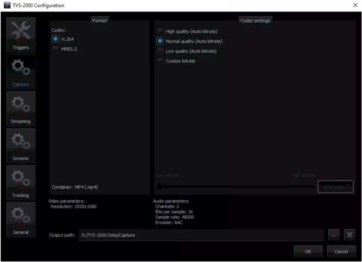
The CODEC supports the video formats listed below:
1080i60 / 59.94 / 50
1080p60 / 59.94 / 50 / 30 / 29.97 / 25
720p60 / 59.94 / 50
The user can perform simple manual settings such as selection of low, normal, high and customized quality. All other parameters such as profiles, bitrate and etc. are configured internally. Selection of custom bitrate allows the user to customize the recording bitrate. In addition, the user is also allowed to define the default captured video file saving directory.
After all capture settings are configured, to start recording the live program, click the Capture button and the button will turn amber as shown in the diagram placed at the beginning of this section. Click the Capture button again to stop recording and the recorded program will be placed in section 5 of the media tab (media 1 and 2).
In addition to program video recording, the user can also grab instantaneous images on the Program view by clicking on the STILL/GRAB button. The grabbed images are saved in PNG format.
The grabbed images will be added to section 5 of both Still tabs of the Media Bin (Still 1 or Still 2).
4.10 Program Video Stream
This function makes sending the broadcast signal in the form of an Internet data stream possible. As a result, live programs can reach all viewers in real time, even in remote areas. TVS-2000A is the main element for such realization because in addition to creating a broadcast signal, it is also capable of converting the broadcast signal into a network data stream.
To start Internet broadcasting, the user should:
- Generate a source signal – made available by Live Production;
- Convert the signal to a format supported by Internet connection;
- Trigger online broadcast by clicking on the STREAM button shown below.
To configure the streaming setting, click located on the right of the stream button to open the configuration window as illustrated below. Define your streaming service and configure video and audio settings accordingly. The available streaming services are Niconico, UStream, Youtube and Custom.
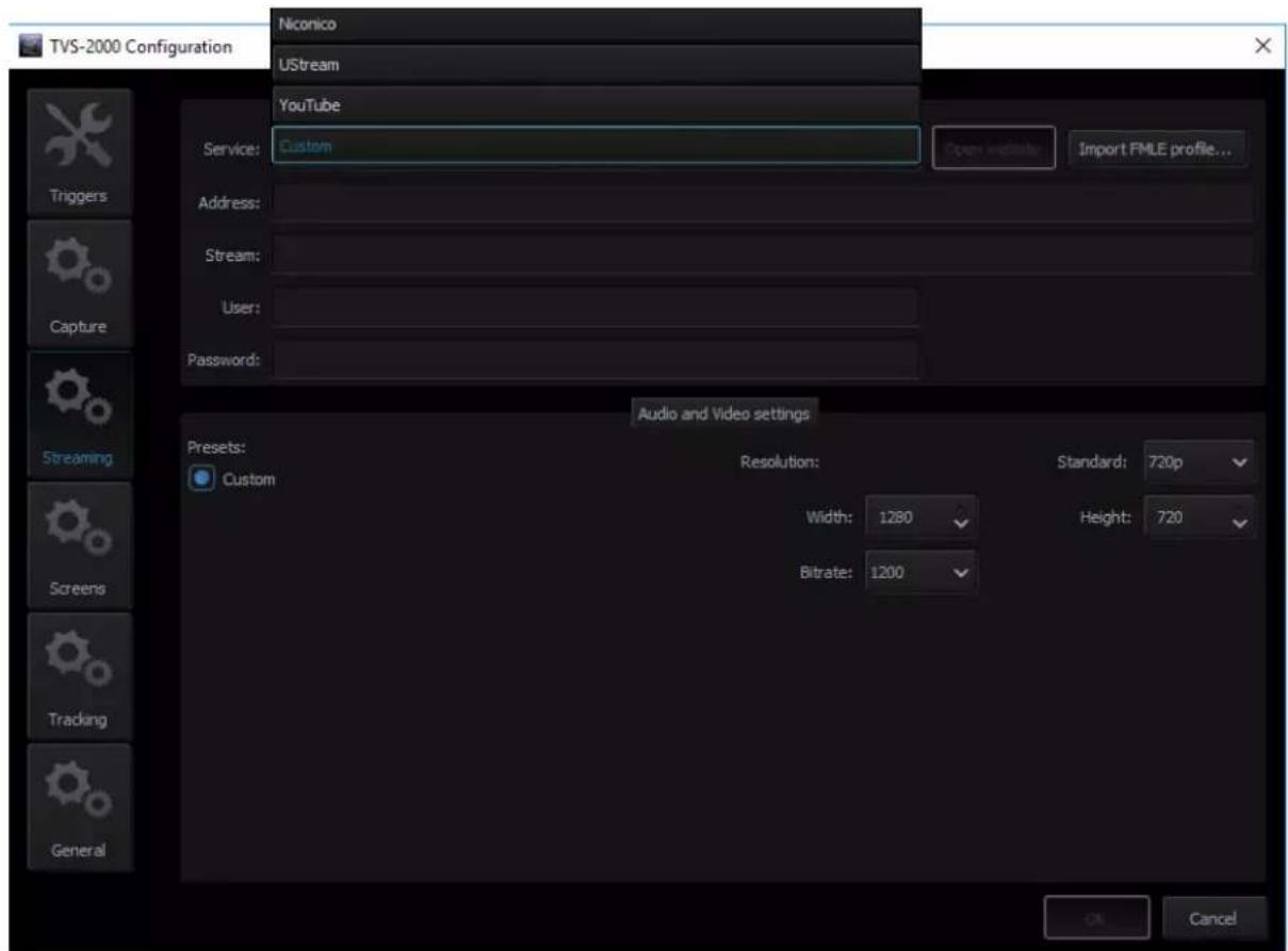
After configuring the stream setting, you may also save your configuration in xml format on the hard disk for future use. To import the configuration file, simply click the "Import FMLE profile..." button to start the import process.
4.11 Tracking Cameras
The Camera Control Card allows connection of two PTC-150 cameras to the TVS-2000A via RJ-45 ports such that they can also be controlled on the RMC-280 Virtual Studio Remote Control Unit.

After connecting the tracking camera (PTC-150) to the camera control card as shown in the diagram above, you may enable its tracking feature in the “Tracking” tab of the TVS-2000A Configuration window.
Note: Please remember to enable the "PTZ INFO. Output" under the "Remote Control" option on the camera's main menu.
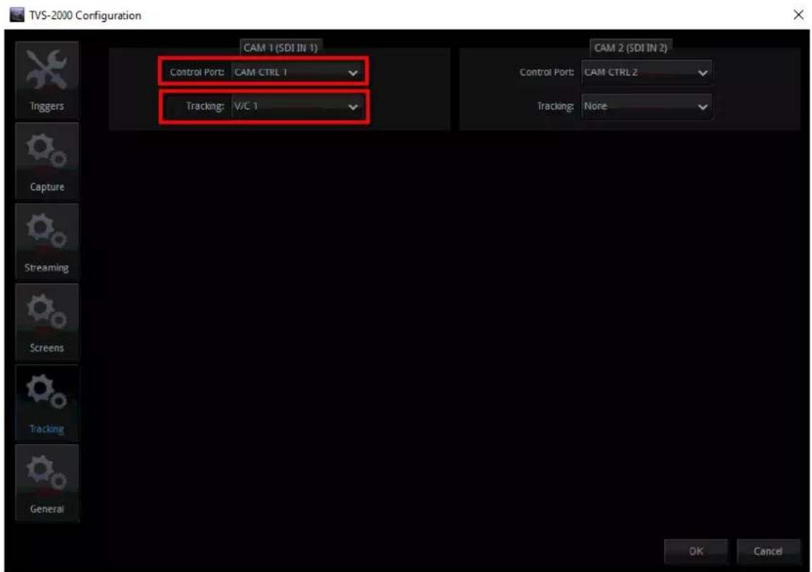
In the example above, on the CAM 1 (SDI IN 1) pane, the Control Port is set to CAM CTRL 1 with the connected camera assigned to V/C 1 where the user will be able to configure different lens positions to track movements of the talent. See Section 4.4 to configure V/C 1 for camera tracking purpose.
*The Tracking source will be the top layer of the tracking V/C. All the other 3D virtual element will stay behind it.
Chapter 5 Chroma and Luma Keys
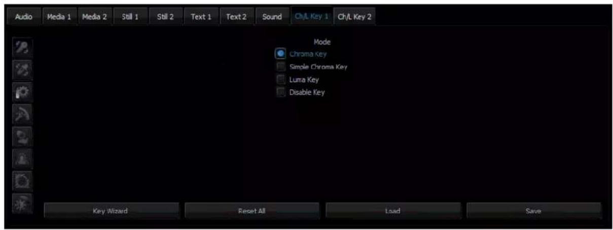
Keying is a special filter that the TVS-2000A uses to remove a specific color (e.g. Green) from the image by applying the filter to the input CAM. CH/L Key 1 applies the filter to the input CAM 1 and CH/L Key 2 applies the filter to the input CAM 2. In this way, for example, talent on a green backdrop can be placed on any virtual background after chromakeying is enabled. The TVS-2000A system supports three keying modes: Chroma Key, Simple Chroma Key and Luma Key.
- Chroma Key Mode – This function enables TVS-2000A to be used for chromakeying Camera input is fed with object on a green or blue backdrop. Background is generated by PC or any other media sources.
- Simple Chroma Key Mode – This function enables TVS-2000A to be used for simple chromakeying by performing quick settings of matte, shadow, despill and garbage mask.
- Luma Key Mode – This function enables TVS-2000A to be used for luminance-based keying. Camera input is fed with object on a black or white backdrop. Background is generated by PC or any other media sources.
To ensure the best quality, the keying function has a number of parameters available for the user to set the optimal keying. The subsections below outline the Chroma Key configuration process in detail.
5.1 Key Selection
Click the button 📄 select the desired key mode as depicted in the diagram below.
5.2 Chroma Key
After selecting the desired key mode, the next step is to select the colour to be keyed out.
Clicking on the chrominance keyer button ☐ to enter the configuration screen as shown in the diagram below. This setting depends on the keying background used. There are two possibilities: green or blue. The choice is made by clicking on Background Color in the Chrominance Keyer section.
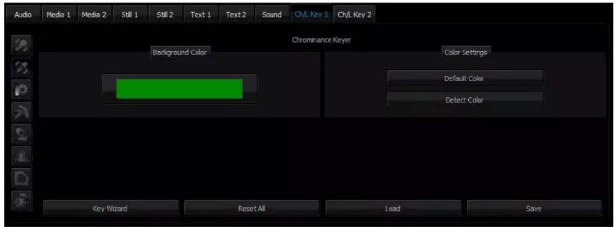
If the colour of the keyed out background is not uniform, the user can make use of the Detect Color button, which will calculate the background's LRGB parameters using the automated average. If the parameters cannot be accessed, the user will be notified about it via a message window, after which the colour will be reset to default. The Default Color button is used to select the default colour.
5.3 Matte Control
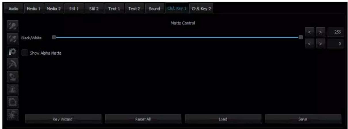
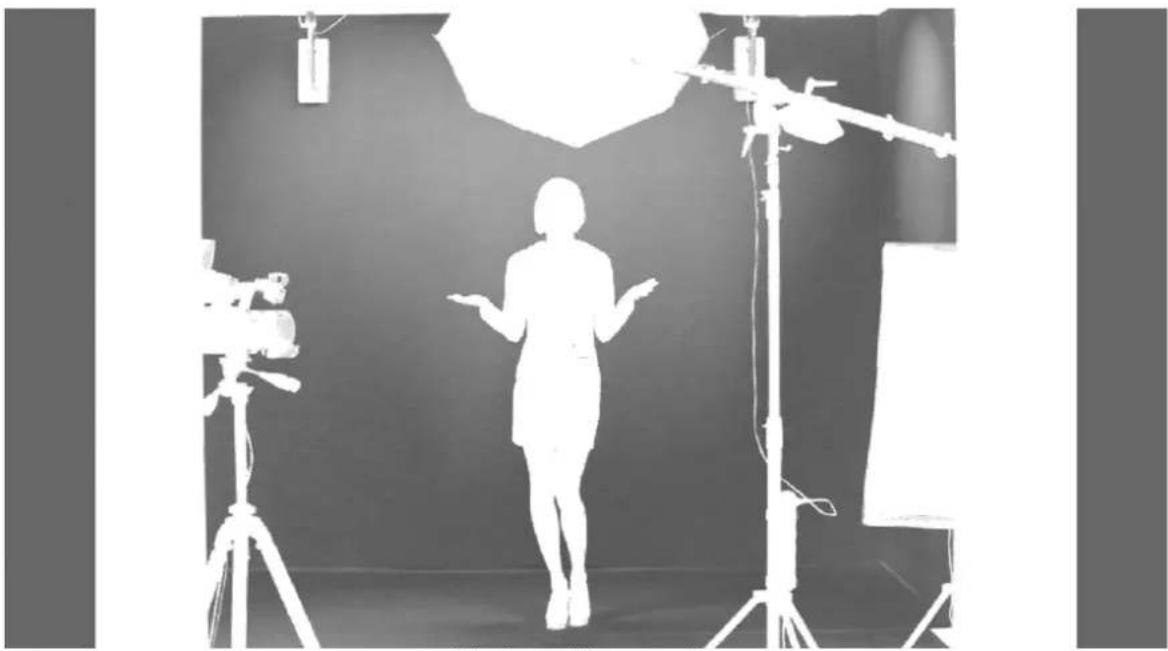
Click the Matte Control button enter the preliminary keying setting page. This is done with the Show Alpha Matte function, which – after a checkbox is checked – will show a matte view for which colours closer to white are non-transparent and those closer to dark are transparent.
natural_image
Silhouette of a person standing in front of a studio setup with camera and lighting equipment (no visible text or symbols)The Show alpha matte view
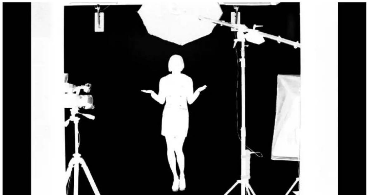
The intended result is to make the mask background colour as close to perfect black as possible. In order to do that the Black Level slider should be moved until black is distributed as evenly as possible on the mask background.
natural_image
Black-and-white photo of a person standing in front of professional lighting equipment including a camera and umbrella (no visible text or symbols)A view after a Black level adjustment
If the slider is moved to the extremes, the other objects will lose their properties and become non-transparent; this is why the function should be applied sparingly so that small differences are still discernible in the distribution of the black background.
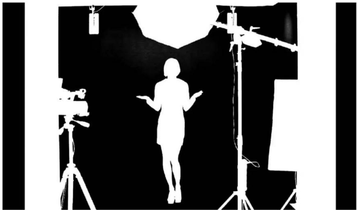
The next step is to obtain a uniform distribution of white on objects which will remain fully non-transparent. This uneven distribution may arise from the fact that the colours of the object may have colour components close to the keying colour. In this case an adjustment can be made using the function known as White Level.
By moving the slider from the maximum value to the left, you can obtain a perfect distribution of white on a given object.
natural_image
Silhouette of a person standing in front of a camera setup with tripod and equipment (no text or symbols visible)A view after a White level adjustment
In many cases, the option White Level will be used in conjunction with the option Black Level in order to obtain the most possible effective settings of the black background, with no loss on white objects and vice versa.
5.4 Tolerance Correction
As seen in the view after a White Level adjustment, an extension of the range by means of the White Level function usually results in the restoration of a uniformly black surface to slight grays. In this case, in order to adjust the grayness, two further functions from the Tolerance correction section are needed. Click the tolerance correction button to enter the Tolerance Correction configuration screen.
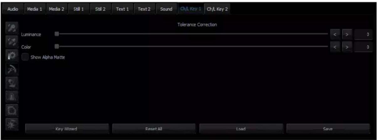
The first function is Luminance and it improves the structure of the uniform colour of the white mask.

The second function is called Color and its use leads to the restoration to a uniform black structure of the background.

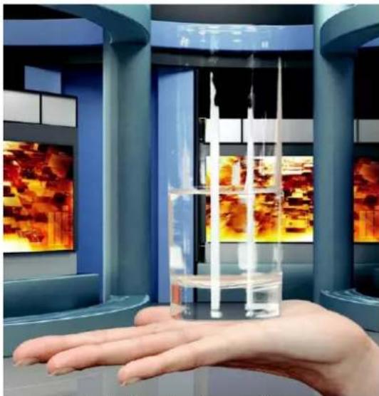
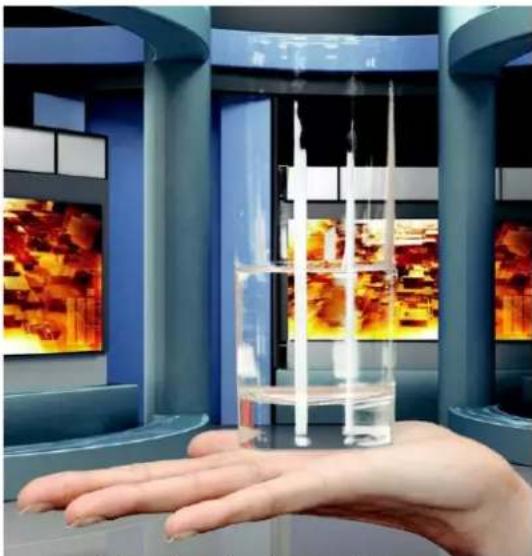
It improves in particular the visibility of an object in the case of a significant difference in luminance between the background and the object. This means that semi-transparent objects, e.g. a glass or glasses, become more distinct. A view ‘before’ and ‘after’ an adjustment is presented in the two pictures below.
A view 'before' and 'after'
natural_image
Hand holding a transparent cylindrical container with floating objects, set against a modern exhibition hall with colorful panels (no visible text or symbols)A view before a Luminance adjustment
natural_image
Hand holding a transparent cylindrical container with liquid inside a blue-tinted exhibition hall (no visible text or symbols)A view after a Luminance adjustment
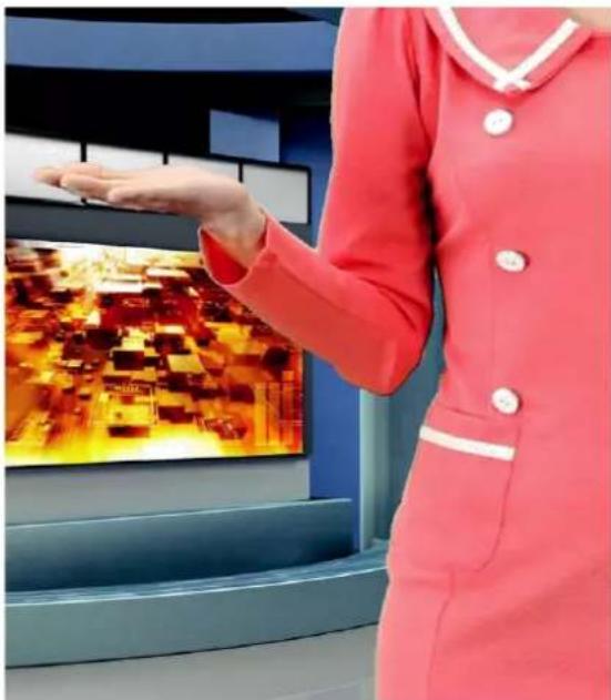
The Color function is also used to bring about another effect. Once the option Show alpha matte is switched off and the real picture is restored, it is possible to eliminate unnatural outlines. This can be done by improving the border value between the keyed colour and the object.
natural_image
Person in red uniform interacting with a touchscreen display showing a thermal image (no visible text or symbols)A view before a Color adjustment
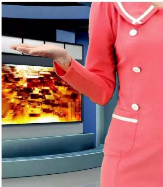
natural_image
Woman in red uniform interacting with a touchscreen display showing a thermal or electronic circuit (no visible text or symbols)A view after a Color adjustment
5.5 Spill Correction
Spill correction removes keying colour remains (Despill). Once the correct mask is set, the functions in the Spill correction section will eliminate the reflection of the colour of the keyed background in the object.
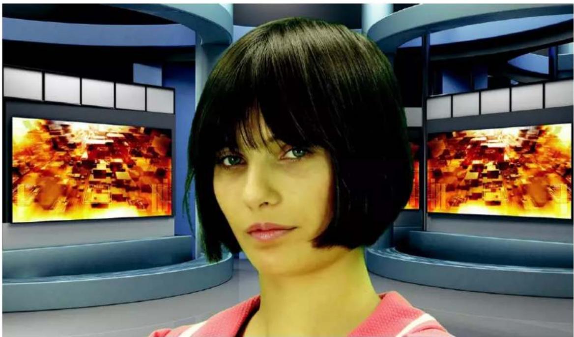
natural_image
Woman with short black hair in a futuristic control room with large digital screens (no visible text or symbols)Impact of the background colour on the object – a view before a Despill correction
Click the Spill Correction button

enter the setting page.
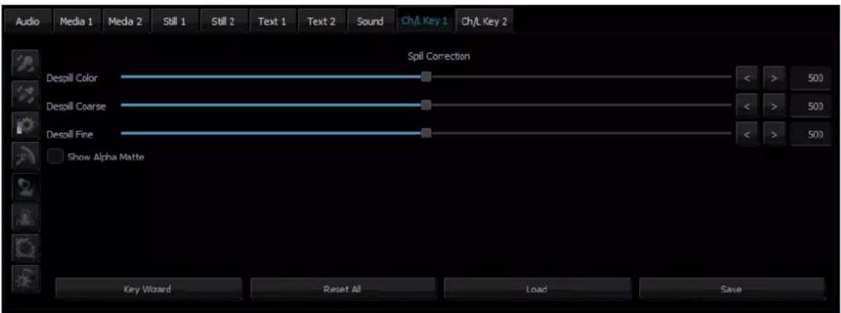
Despill color and Despill coarse belong to the functions for the preliminary elimination of unwanted colours, and are based on the RGB space.

The Despill color/Despill coarse slider section
Once the Despill color slider is moved to position 0 (the left-hand side), the algorithm will automatically remove the green colour component if this is the keyed colour (similarly – blue if the background is blue). Once the Despill color slider is moved to position 1000 (the right-hand side), however, the algorithm will automatically add the red colour and the blue colour (if the keyed colour is green) or red and green (if the background is blue).
The value of the algorithm is controlled by means of the Despill coarse function. If the keyed background is green, after a certain threshold of the Despill coarse function is crossed, the green component is entirely eliminated from the object in the RGB (red, green, blue) space, which results in the transition of colours into the purple (magenta) area.
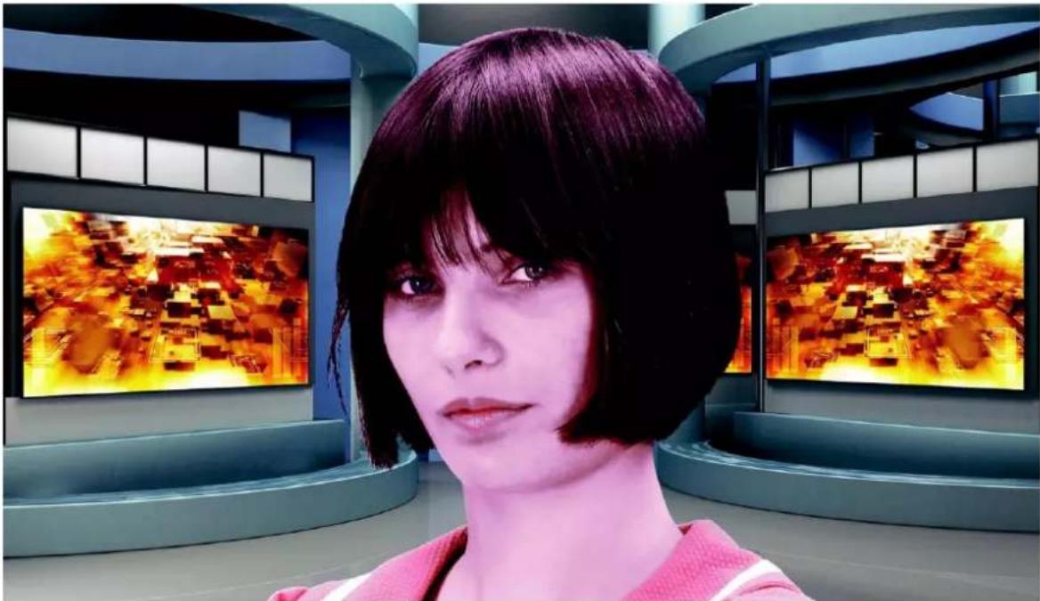
natural_image
A person with short dark hair in a futuristic exhibition space, facing two large screens displaying abstract digital patterns (no visible text or symbols)A view after the green component has been eliminated
Another function enables a more accurate adjustment of the above problem.
The use of the Despill fine function eliminates the keyed background colour from the object, but this time on the basis of the chrominance components.

The Despill fine slider
After the application of Despill coarse, which is used for preliminary correction, more accurate adjustments can be made, and so the Despill fine settings may not have any significant impact on the algorithm if Despill coarse is set to high.
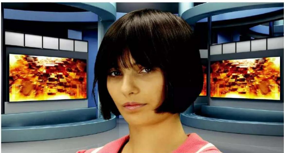
natural_image
Woman with short black hair in a futuristic studio with large digital screens (no visible text or symbols)Impact of the background on the object – a view after a Despill correction
5.6 Edge Correction
Additional correction is applied to improve quality. Click the Edge Correction button enter the setting screen.

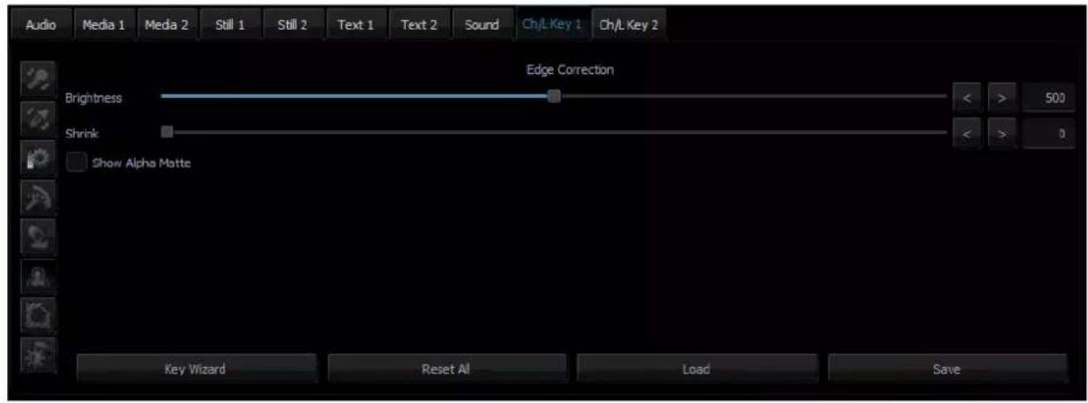
The Edge Correction function is used to correct semi-transparent areas (e.g. hair ends that need to be darkened or brightened) in order to make an object look natural.

The Edge brightness slider
5.7 Garbage Mask
Garbage mask is used to reduce the mask size by cutting it (in all of the possible directions: left, right, up, down). Click ☐ configure the garbage mask.
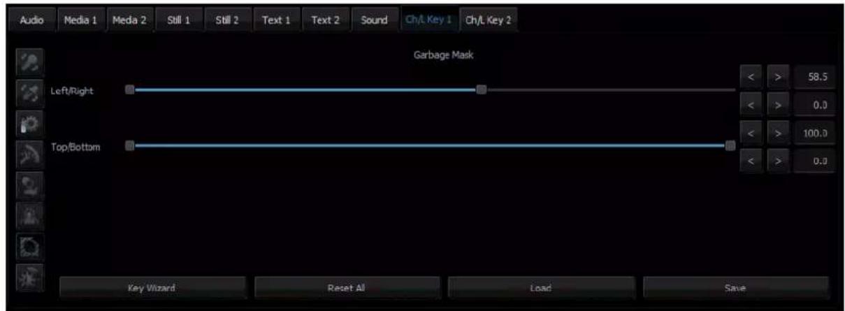
The Garbage mask section
This function is used if the view of the keyed background is not large enough to fill in the entire object shot.
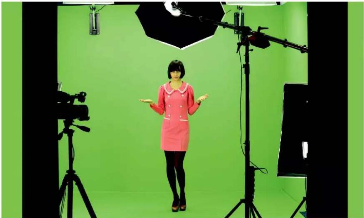
natural_image
Interior studio scene with a person in a red dress standing in front of green walls, surrounded by professional lighting equipment and a camera on tripod (no visible text or symbols)A view from the camera area
By cutting the remaining elements by means of the sliders Left, Right, Top, Bottom, it is possible to place the object within the area of the keyed background.
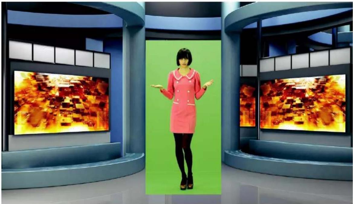
natural_image
Interior of a modern TV studio with two large screens displaying animated characters in the background (no visible text or symbols)A view after a Garbage mask correction with the keying algorithm switched off
After enabling the chroma keying function, the following effect is obtained.
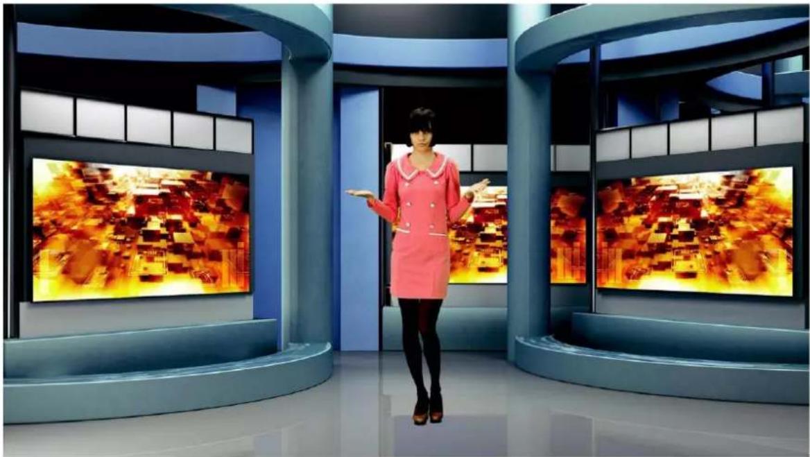
natural_image
Interior of a modern TV studio with two large screens displaying animated characters, no visible text or symbols on screens or surroundings.A view after the Garbage mask correction with the keying algorithm switched on
Comments: It should be kept in mind that in this case the object may only move within the area of the cut off mask – otherwise the object will disappear.
Furthermore, if the Garbage mask sliders are used, it is possible to check whether the previous settings were correct and whether they had any influence on the final look of the virtual background. By moving for instance the Left slider within its full range, no noise, colour shifts or changes in the background grayness should be visible.
5.8 Post Correction
Post Correction matches the object to the conditions of the virtual background. The following functions illustrated in the diagram below are used for post-correction of the object and have no effect on its virtual background.
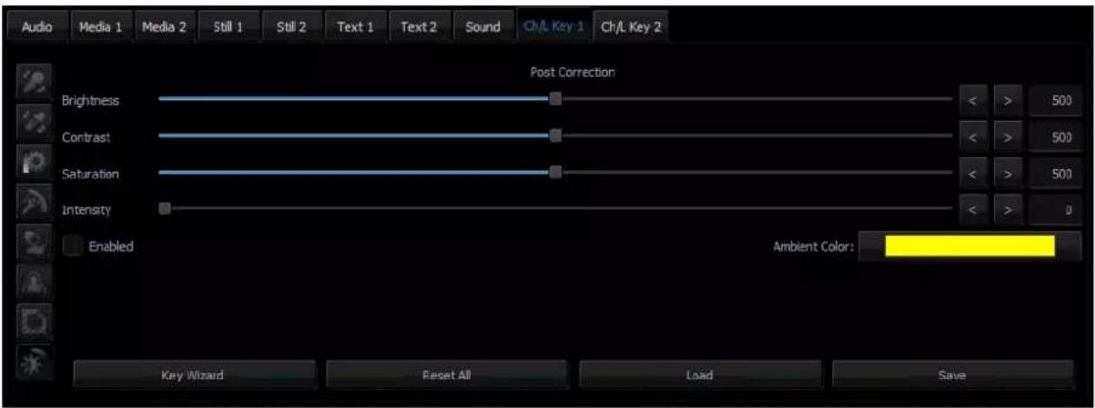
- Brightness – this enables additional colour brightness to be introduced into the picture.
- Contrast – this enables the contrast between colours to be increased.
- Saturation – this enables colour saturation to be boosted.
- Intensity – this enables the ambient colour intensity to be set.
Chapter 6 Fast Chromakeying
The TVS-2000A comes with two special features that allow the user to perform fast chromakeying. The two special features are Simple Chroma Key and the Wizard.
6.1 Simple Chroma Key
Simple Chroma Key mode gives the user the capability to apply the chromakeying effect with a single mouse click.
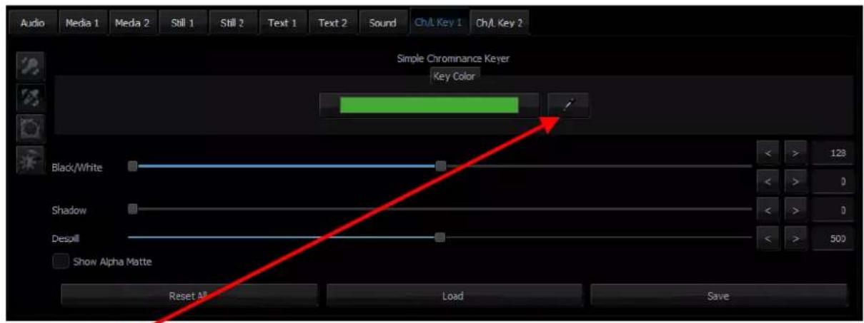
Click

the system will automatically select the optimum chroma key color.
6.2 Wizard
The Chroma Key Wizard is designed to guide the user to perform chromakeying step by step. Click the "Wizard" button enclosed in the red rectangular box as shown in the diagram below to start the chromakeying wizard.
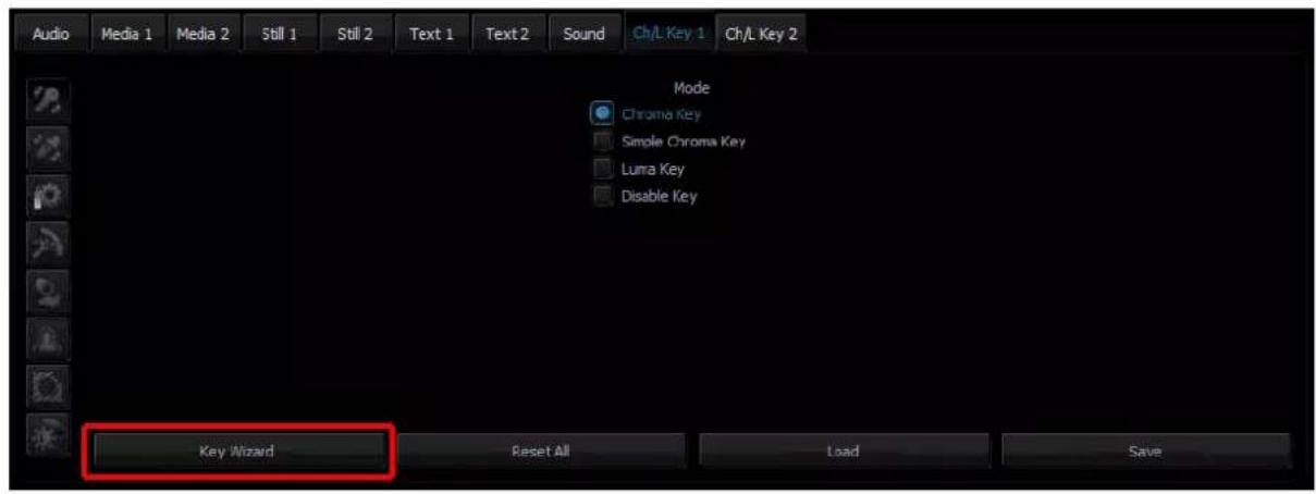
Chapter 7 3D Studio Editor
7.1 Open the 3D Studio Editor
Follow the steps below to open the 3D Studio Editor:
1 Open the TVS-2000A program to enter the Production interface.
2 Click at the bottom left corner to open the interface for selecting raw materials.
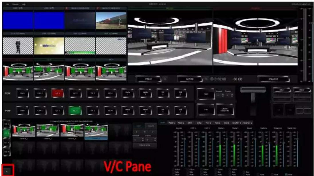
3 Click the "Studio Editor" button at the bottom right corner of the V/C pane to open the user interface of Studio Editor.
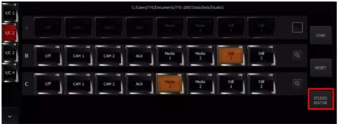
7.2 Studio Editor Overview
As shown in the diagram below, the Studio Editor consists of the virtual camera customization tool, view of the scene and scene object selection.
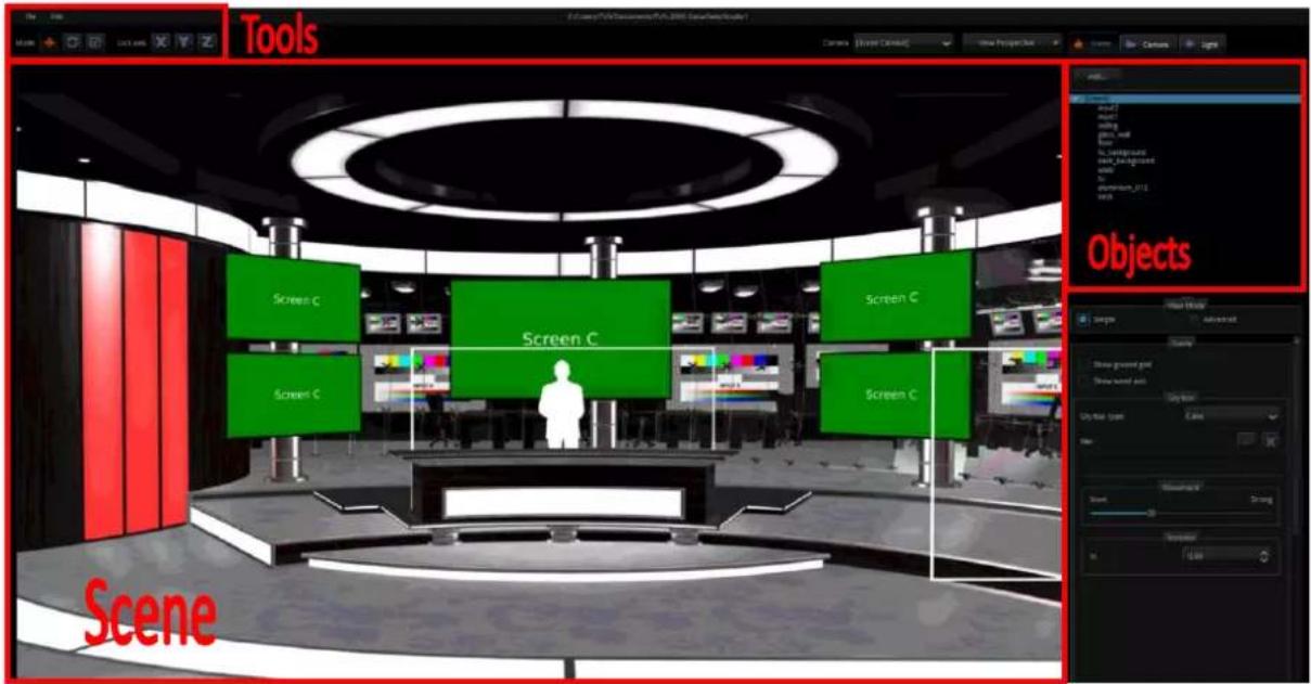
Virtual Scene and Light Customization Tool
There are three control modes for moving the virtual scene and light. Each control mode is described in the table below.

All direction
Moves the virtual scene and light freely.

Rotation
Rotates the virtual scene and light objects in all directions and angles

Zoom
Zooms IN/OUT virtual scene objects. However, the light objects can not be Zoomed IN/Zoomed OUT.
"Lock Axis" Mode
The Axis Lock function allows users to lock the X, Y and Z axis of the virtual scene.
View of the Scene
![View Perspective View Perspective View Left View Right View Top View Bottom View Front View Back Scene Camera Light Add Close Remove Rename [Scene Camera] Camera_1 Camera_2 Camera_3 Camera_4 Camera_5 Camera_6 Camera_7 Camera_8 Camera_9 Camera_10 Camera_11 Camera_12 Camera_13 Camera_14 Camera_15](/content/2026/05/998455/images/71cca635a825ff6d76a05c0639b6cca3a576e0eba7018f0978ff0eff38f20aca.jpg)
The camera and the viewing angle are configurable. The user is allowed to select up to 15 cameras. The angle of view can be previewed in the scene window. In addition, the user is allowed to select left, right, top, bottom, front and rear views.
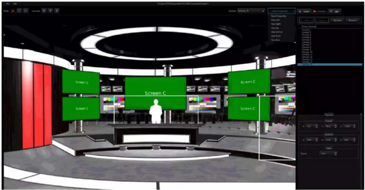
Virtual Set Object Selection
The three major options are “Scene”, “Camera” and “Light.” In this option, users can “Add”, “Clone”, “Remove” and “Rename” the scene and cameras as they wish. However, the Light option can not be Added, Cloned, Removed or Renamed by users.
Scene
![[Scene] input1 ceiling glass_wall floor tv_background desk_background walls tv aluminum_012 desk View Mode Simple Advanced Scene Show ground grid Show world axis Sky box Sky box type: Cube File: Movement None Strong Rotation Y: 0.00](/content/2026/05/998455/images/347e1d790d758e66745ccf425e0cd14c81c0e364e830a633556114cd513e2184.jpg)
In this option, you will be able to add a new object to the scene.
| Add... | This “Add” button allows users to load pre-saved TVS-2000A scene file in .n3d, .obj and .fbx file formats. Please press this “Add” button and then a prompt window will be shown for users to load their desired scene file. | |
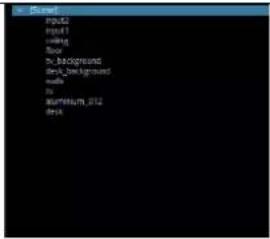 | In the pane which is shown as the left diagram, users can see all of the elements of the selected scene file including grouping objects and non-grouping objects. | |
 | View ModeThis View Mode option allows users to choose Simple Mode or Advanced Mode for viewing all of the elements of the loaded scene. Please choose the Simple/Advanced by clicking the checkbox. | |
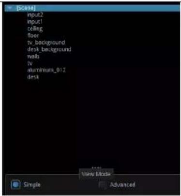 | Simple ModeOnce the simple mode is selected, all of the objects will be shown as the left diagram. All of the objects such as the floor and ceiling will be shown in groups. | |
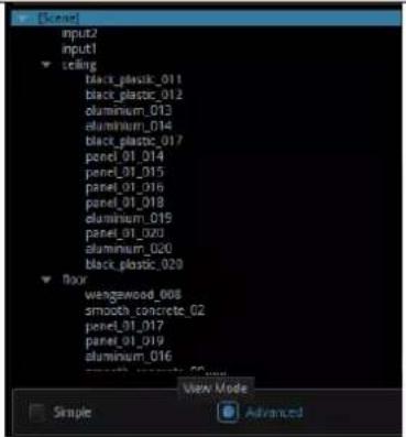 | Advanced ModeOnce the Advanced Mode is selected, users can show all of the objects in each group by pressing the arrow at the left side of each group. | |
| Show world axis | Show World AxisIf this checkbox is checked, the X Axis, Y Axis and Z Axis of the scene will be shown on the screen to give users a reference for directions. | |
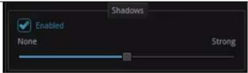 | ShadowThe Enabled check box of the Shadow option allow users to enable the shadow effect of the objects in the scene. Once the checkbox is clicked, the shadow effect is enabled. Moreover, the slider allows users to adjust the strength of the shadow. | |
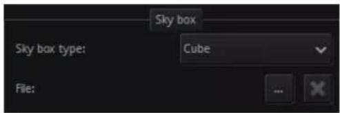 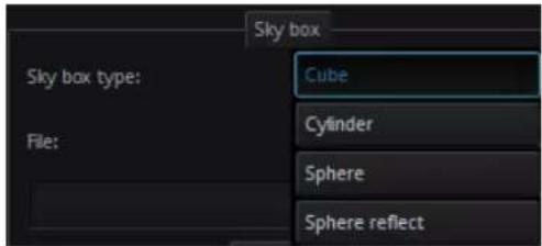  | SKY BoxThe SKY Box option helps users to load a pre-saved still picture in JPG, PNG, JPEG or BMP formats to be the environment map of the TVS-2000A virtual studio. Please follow following steps for loading pre-saved still pictures to be the environment map of the TVS-2000A virtual studio. The detailed descriptions for the SKYBOX, please refer to the SKY BOX related paragraphs. | |
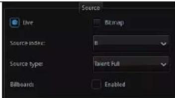 | Movement SliderThe Movement Slider helps users for zooming in/zooming out the environment map image. | |
| SourceIf the group of the Input 1 or Input 2 is selected, there are five source types for users to select including Talent Full/Talent Middle/Talent Desk/Screen/Other. If the Enabled checkbox of the Billboard option is ticked, the selected talent will face to the camera lens. | ||
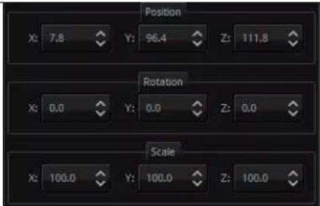 | Camera Position, Rotation and ScalingThis pane allows users to adjust the X/Y/Z axis to determine the position, rotation and scaling of the selected talent or object.Note: The position, rotation and scaling of talents and objects can be adjusted by using a mouse in the virtual scene editing window. | |
SKYBOX
TVS-2000A provides three types of the SKYBOXs including Cylinder, Sphere and Sphere reflect. The SKYBOX function allows users to insert still pictures in different formats such as .png and .jpg for different SKYBOX effects. After that, this still picture coated with different SKYBOX effects can be the environment map of the outermost layer of the virtual scene. The SKYBOX effect can be used to be the environment map. However, it can also affect the environment reflection of the virtual scene.
Please see following descriptions about the operating procedure of the SKYBOX function.
Cylinder
Step 1: Please load a pre-saved virtual scene from the route File-> Load Studio
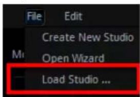
Step 2: Please select the Cylinder effect from the SKYBOX type drop-down menu.
Step 3: Please press the button to select a still picture from the prompt window to be the environment map(users can select still pictures in .png,.jpg, .jpeg and .bmp formats) Step 4: Users can see that the loaded virtual scene is coated with the Cylinder SKYBOX effect which is shown as following diagram.
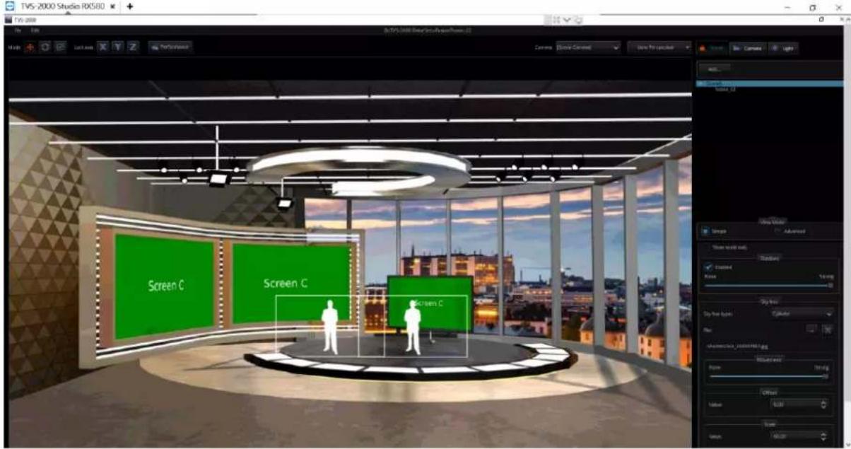
The Cylinder SKYBOX effect allows users to adjust three parameters including Movement, Offset and Scale.
Movement: Users can use the Movement slider to Zoom-In and Zoom Out the environment map. Slide the slider toward the "None" side for zooming in the environment map and slide the slider toward the "Strong" side for zooming out the environment map.
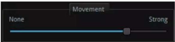
Offset: The Offset function allows users to adjust the environment map to the upside or downside by entering different values. If the negative value is entered, the environment map will move to downside and if the positive value is entered, the environment map will move to upside. The higher value will cause substantial range of movement.
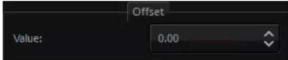
Scale: The Scale function allows users to enter different values for scaling up and scaling down the environment map. Please enter higher value for scaling up the environment map and lower value for scaling down the environment map.
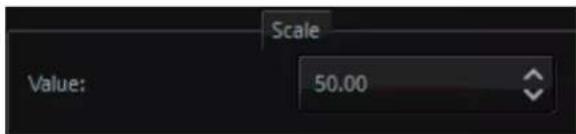
Rotation: The Rotation function allows users to rotate the environment map by entering different values.
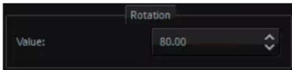
Sphere
Step 1: Please load a pre-saved virtual scene from the route File-> Load Studio
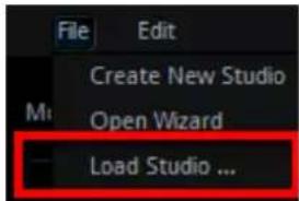
Step 2: Please select the Sphere effect from the SKYBOX type drop-down menu.
Step 3: Please press the button to select a still picture from the prompt window to be the environment map(users can select still pictures in .png, .jpg, .jpeg and .bmp formats) Step 4: Users can see that the loaded virtual scene is coated with the Sphere SKYBOX effect which is shown as following diagram.
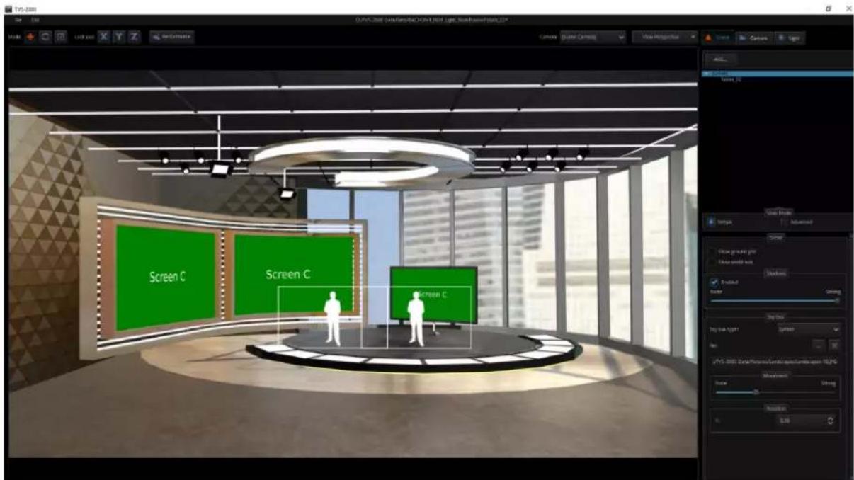
The “Sphere” SKYBOX effect allows users to adjust two parameters including Movement and Rotation.
Movement: Users can adjust the zoom-in and zoon-out of the environment map by the movement slider. Slide the slider toward the "None" side for zooming in the environment map and slide the slider toward the "Strong" side for zooming out the environment map.
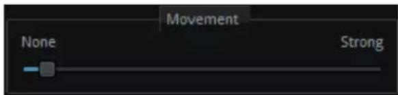
Rotation: The Rotation function allows users to adjust the rotation of the environment map which is coated with the Sphere SKYBOX effect.
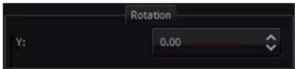
Sphere Reflect
Step 1: Please load a pre-saved virtual scene from the route File-> Load Studio
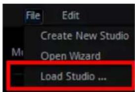
Step 2: Please select the Sphere Reflect effect from the SKYBOX type drop-down menu.
Step 3: Please press the button to select a still picture from the prompt window to be the environment map(users can select still pictures in .png,.jpg, .jpeg and .bmp formats) Step 4: Users can see that the loaded virtual scene is coated with the Sphere Reflect SKYBOX effect which is shown as following diagram.
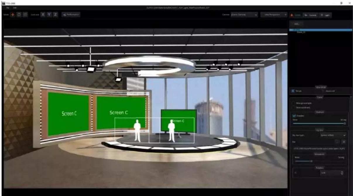
The Sphere Reflect effect provides two parameters for uses including Movement and Rotation.
Movement: Users can adjust the zoom-in and zoon-out of the environment map by the movement slider. Slide the slider toward the "None" side for zooming in the environment map and slide the slider toward the "Strong" side for zooming out the environment map.
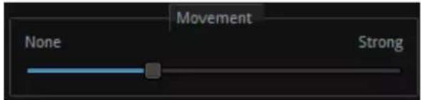
Rotation: The Rotation function allows users to adjust the rotation of the environment map which is coated with the Sphere SKYBOX effect.
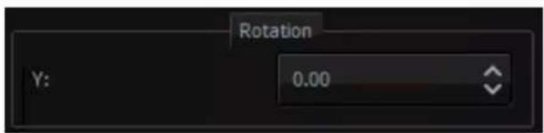
How to modify properties of a 3D object?
The user is allowed to import any 3D models in FBX and OBJ formats. The model must contain PBR effect in order to display correct colors in the TVS system. To modify properties and color of the imported object model, first select the object that you want to modify, and then modify the object properties and color in the Material pane. Please follow following steps for modifying properties and color of the objects in the 3D scene.
Step 1: At first, please select the Advanced View Mode.

Step 2: Each object in the virtual scene will be shown in the following pane.
![[Scene] fusion_02 lamp pPipe10 pPipe9 pPipe11 ▶ ceiling1 ▶ stage input_B input_A ▶ wall ▶ screen ▶ frame ▶ floor pCylinder119 floor pPlane11 ▶ tv](/content/2026/05/998455/images/da9d8acf9c50660034b09707a584caff29c845c9f0b0ec843900f72b27e1a2cd.jpg)
Step 3: Please select the 3D scene object that the properties and colors must be modified (Take lamp as an example).
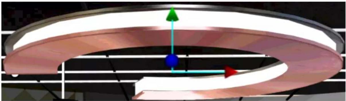
natural_image
3D diagram of a curved mechanical component with colored directional arrows indicating motion or force (no text or symbols)Step 4: The Material pane which is shown as following will be shown for users to select their desired properties and colors for the selected object.
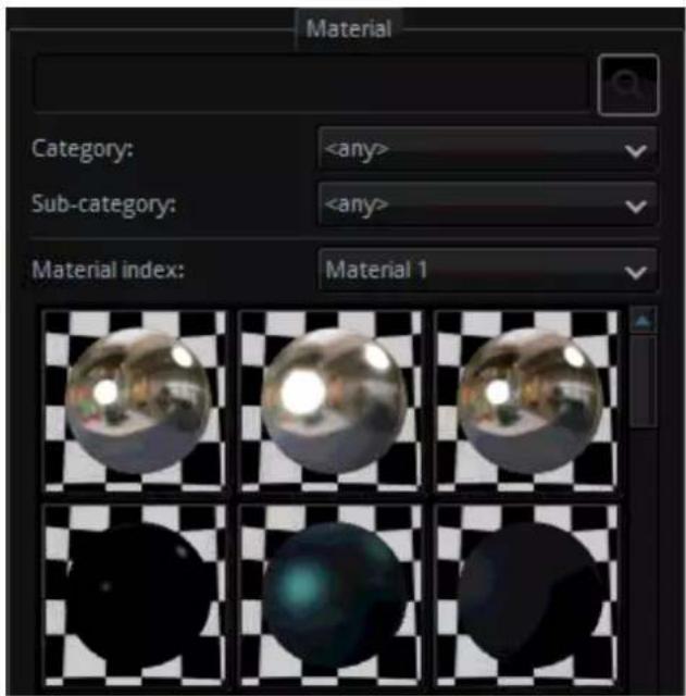
- Search bar for materials and properties: Users can enter pre-saved material properties or colors into the search bar to find them quickly.

Category: Users can press the item in the drop-down menu which is shown as following to select their desired 3D object property.
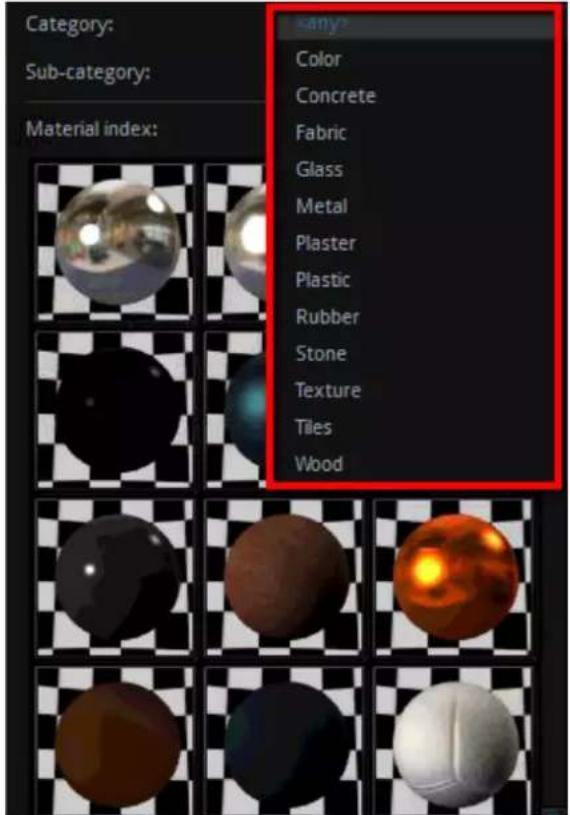
- Sub-category: Users can press the sub-category drop-down menu which is shown as following to select colors of their desired 3D objects.
![[Scene] fusion_02 lamp pPipe10 pPipe9 pPipe11 ceiling1 stage input_B input_A wall screen frame floor pCylinder119 floor pPlane11 tv Simple Category: Sub-category: Material index: Aluminium Azure Beige Black Blue Brick Bronze Brown Brushed Ceiling Checkerboard Chrome Copper Cork Cyan Dark Denim Fiolet Floor Gold Grass Green Grey Iron Lamp Leather Light Marble Matt Oak Orange Ornament Parquet Pine Plywood Red Rouge Sand Sandstone Shiny Siding Silver Smooth Terracotta Tiles Tombac Transparent](/content/2026/05/998455/images/d70b71f7e0f4d0e6884754b66744df6b05791c37e548df1455e81d94f9ba82d0.jpg)
Step 5: When the desired material and color are selected by users, please click the desired material ball and then the property or color of the selected 3D object will be changed successfully.
natural_image
Close-up of a metallic circular ceiling light fixture with reflective surfaces (no text or symbols visible)How to restore the material of the 3D object?
If users want to restore the material of the 3D object to the previously saved situation, please follow following steps.
Step 1: Please select the object which the material must be restored in the scene. (In this example, this object is lamp).
natural_image
3D diagram of a toroidal structure with colored arrows indicating direction (no text or symbols)Step 2: Please press the "Restore material to default" button from the material pane, and then the material of the selected object will be restored to the previously-saved situation.
Restore material to default
![[Scene Camera] Camera_1 Camera_2 Camera_3 Camera_4 Camera_5 Camera_6 Camera_7 Camera_8 Camera_9 Camera_10 Camera_11 Camera_12 Camera_13 Camera_14 Camera_15 Camera Position X: 40.3 Y: 185.6 Z: 2195.9 Rotation X: -0.95 Y: -2.30 Z: 0.00 Other Zoom: 1.14](/content/2026/05/998455/images/1c144f2962d6fadebeb87ec1b04990e316498ac80cc1b4cb78cfe0942b4aa875.jpg)
Camera
The user is allowed to configure up to 15 virtual cameras. The Camera tab allows you to change the camera position to meet the requirements of your video production. The camera can be individually configured in terms of its position, orientation and size.
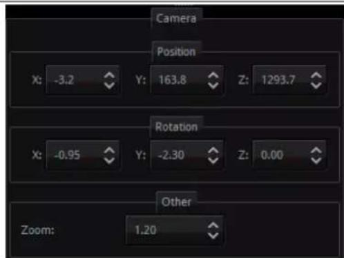
Camera Position, Rotation and Zoom
This pane allows users to adjust the X/Y/Z axis to determine the position, rotation and zooming of the selected camera.
Note: The position, rotation and scaling of talents and objects can be adjusted by using a mouse in the virtual scene editing window.
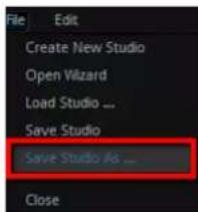
After the settings are stored, please press "Save Studio As" Close from the File drop-down menu. When the settings are stored, the scene must be re-imported and the locations of the virtual cameras can be updated simultaneously in the camera control area. Please go back to the production interface and then press the Load button and then the virtual scene will be re-imported.
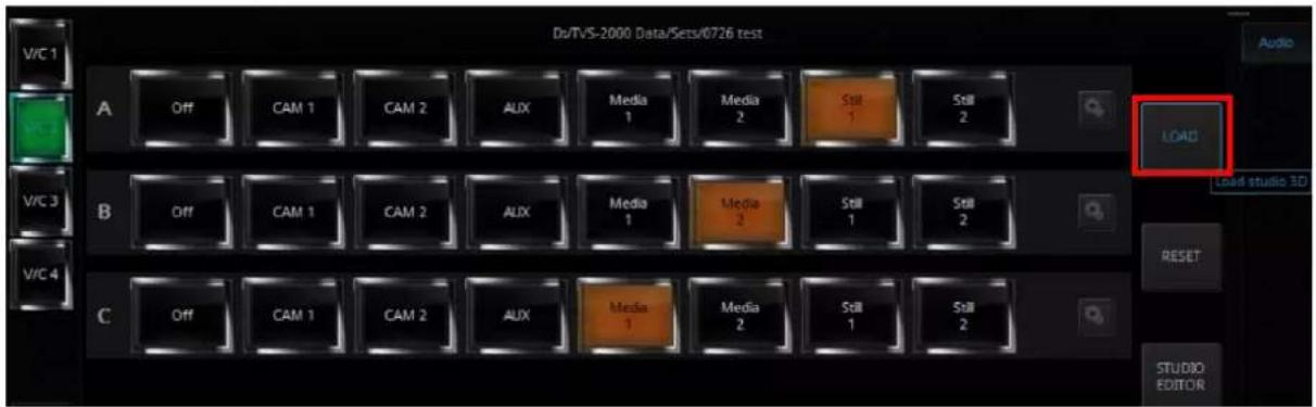
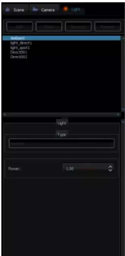
Light
There are four types of light and they are ambient, directional, point and spot. You are allowed to select up to four lights with each light having configurable parameters. Note: The ambient light can not be adjusted by users.
Ambient Light
The ambient light refers to Omni-directional light rays from a point of light. You are allowed to configure the total light output strength (Power). Color and direction cannot be adjusted. Because the ambient light does not create dark shadow, so it is usually used as a supplementary light for simulating indirect lights.
Directional
Directional light is basically used to simulate lights transmitted from afar to light up the scene and other object models. Just like the sunlight rays, the directional light rays travel in parallel and the light strength can be controlled by different colors, therefore it is more appropriate for simulating wide range lights, such as lights from the sky, supplementary to the ambient light and etc. The variable of the directional light is the angle between the direction of the light ray and the object model on which the light is hit. The smaller the angle, the smaller the area of the object model on which the light is shone and the shorter the shadow. On the contrary, the bigger the angle, the bigger the area of the object model on which the light is shone and the longer the shadow. The user is allowed to select the light color and its direction.
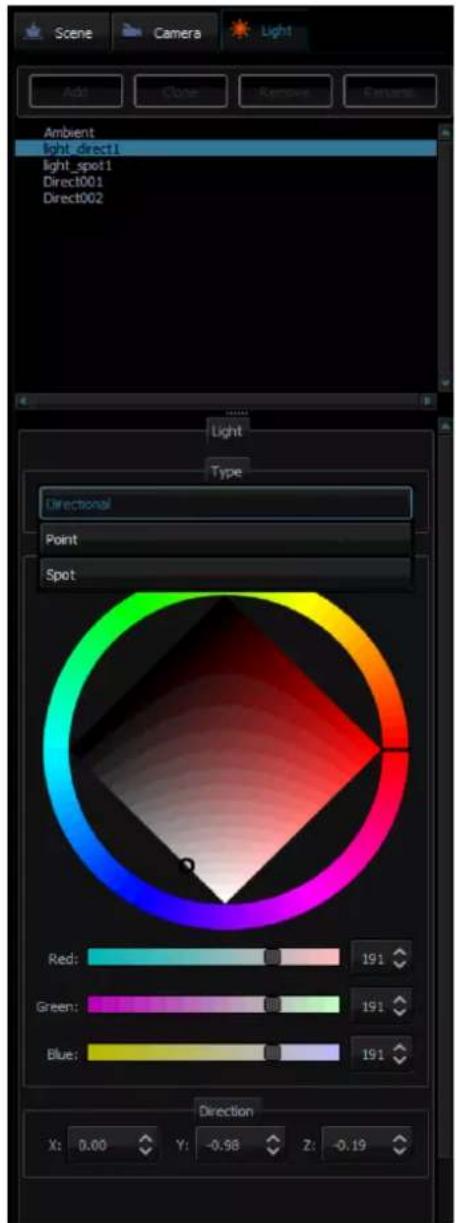
Point
The point light rays are transmitted from a point to the surroundings (Omni-directional) in order to light up the object model. It is similar to the Omni-directional candle light or light bulb in real life. In respective to the location of the light source, the object in the scene will project slanted shadows, thus creating uniform light and transparency effects. This kind of light source is usually used as a supplementary light.
Because most light rays are directional, therefore a dark shadow will form in relative to the direction of the light rays. The Omni-directional point light on the other hand is perfect for lightening the shadow.
The user is allowed to select the light color, position and attenuation.
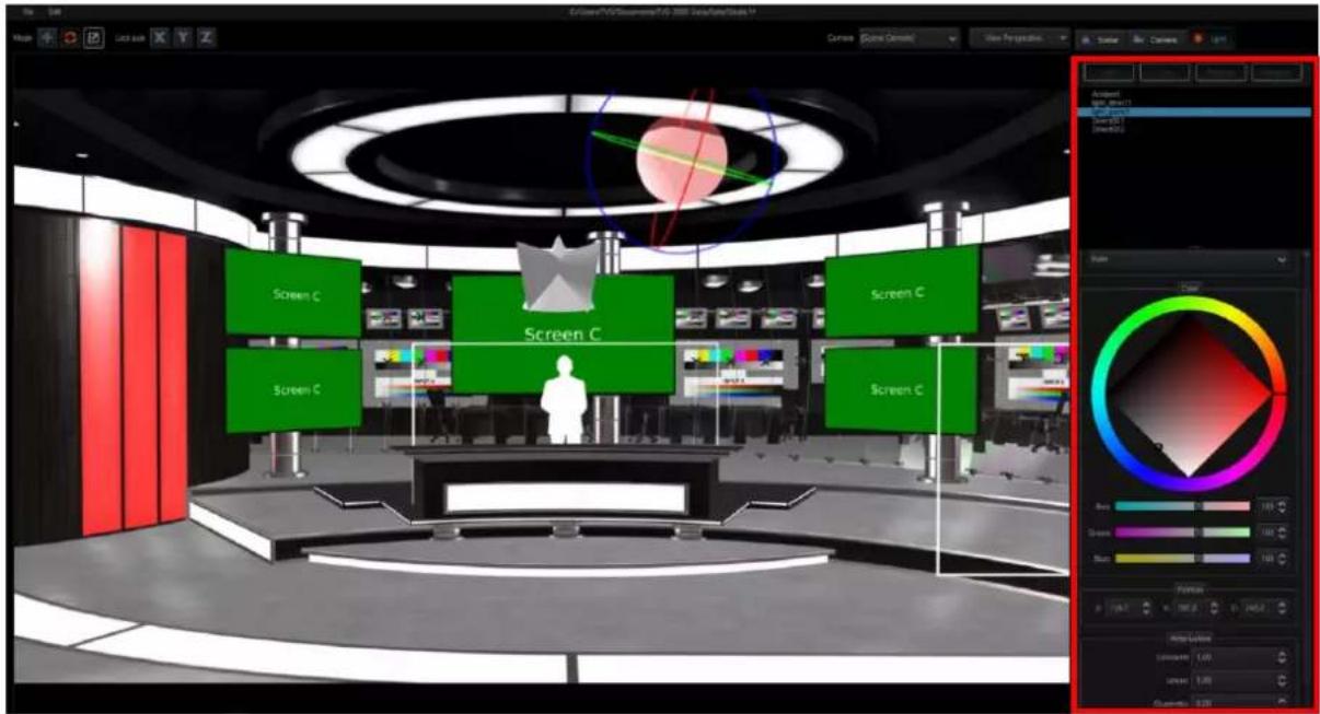
Spot
Spot light is a light source that forms a cone-shaped space of light. The light rays are transmitted from the center of the light source to the cone-shaped space in order to light up the object model within. The spot light is directional because only the object model within the cone-shaped space can be lit up. Also because of its directivity as well as the cone-shaped space formed, the spot light is usually used as the main light source for lighting up the scene and the object model in the scene. The user is allowed to configure the light color, position, and direction as well as the cone-shaped space.
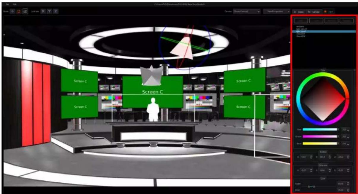
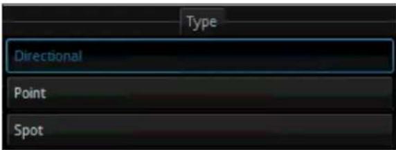 | Light TypeWhen the Light tab is pressed and the light object is selected, this drop-down menu allows users to select their desired light types includingDirectional, PointandSpot. |
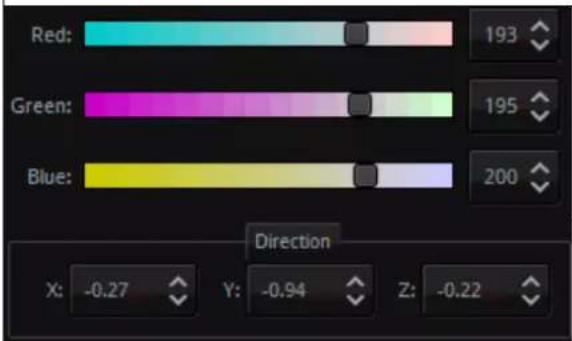 | Color SlidersThose color sliders allow users to adjust the color of the light including Red, Green and Blue. |
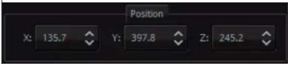 | DirectionIf the directional option is selected, this option allows users to adjust the X, Y and Z axis of the light direction. |
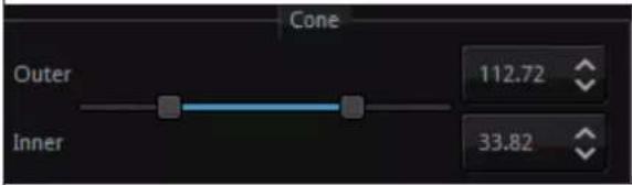 | PositionIf the point option is selected, this option allows users to adjust the X, Y and Z axis of the light position. |
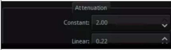 | ConeIf the Spot option is selected, this Cone slider allows users to adjust the inner cone and outer cone of the Spot light. |
| AttenuationIf the Point option is selected, this Attenuation item allows users to adjust the constant and linear attenuation of the light. |
7.3 Studio 3D Editor Wizard
The Studio Editor allows the user to quickly build the scene without having to learn the basics of any 3D editors.
Open the Studio 3D Editor Wizard by clicking the Studio Editor button on the V/C pane.
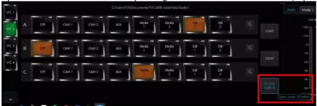
To the top left corner, click "File" and then "Open Wizard" to start creating your scene.
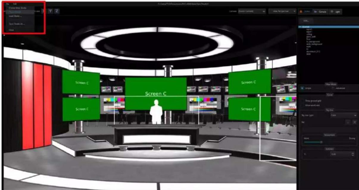
The 3D Studio Editor shown in the diagram above allows the user to quickly create the scene even if you are not an experienced 3D Editor user. There are four function areas on the screen and they are (1) virtual camera customization tool, (2) scene object selection, (3) material template and (4) Decorations object section.
Virtual Camera Customization Tool
The user is allowed to lock the x, y and z axes so that you will obtain a more precise shift while moving the camera.
Wizard
If users want to use Wizard, please click the "File" drop-down menu and then click
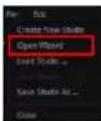
"Open Wizard"
After that, the Wizard will be shown as following diagram.
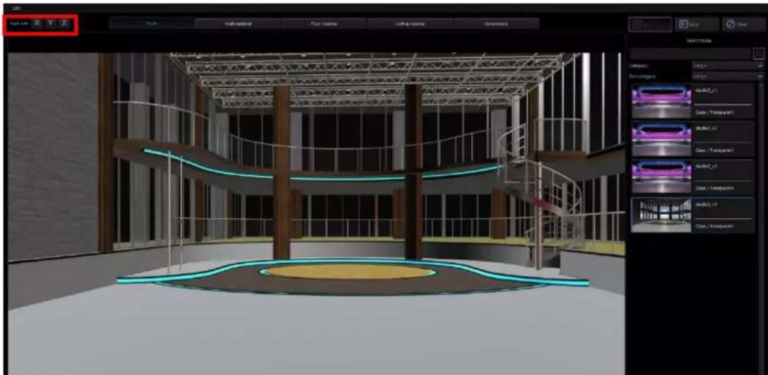
natural_image
3D architectural rendering of a modern building interior with curved staircases and a central circular structure (no visible text or symbols)Scene Objects
This part is related to the templates on the right half of the screen. First select the area of objects that you want to modify and then move the mouse cursor to the templates on the right half of the screen to select the desired materials. The user is allowed to customize
materials for the scene, walls, the floor, the ceiling and other accessories, which form a unique style of the scene.
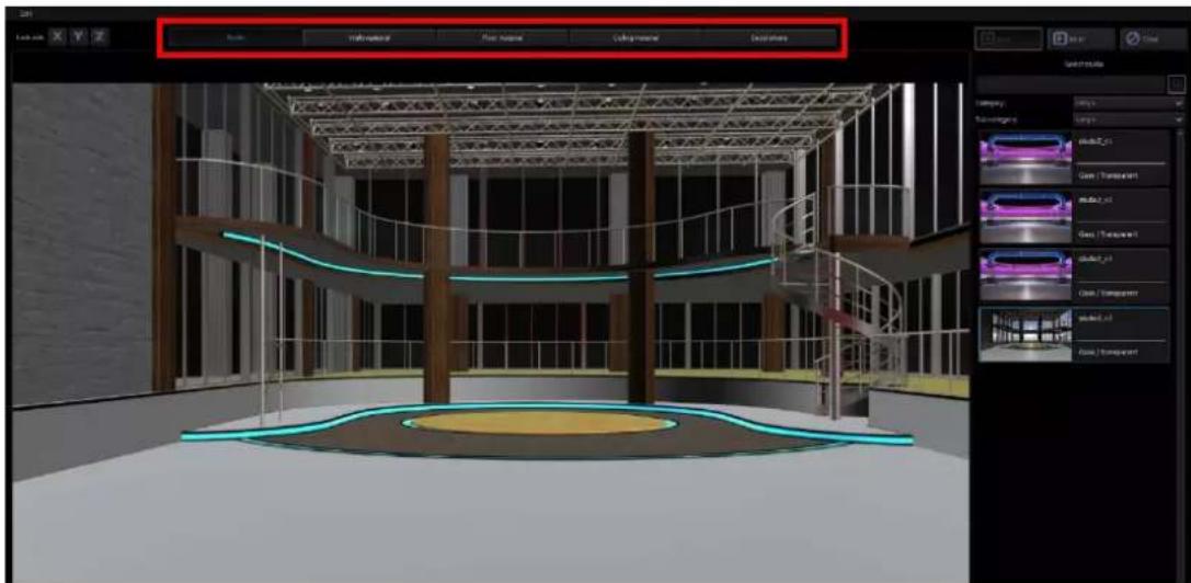
natural_image
3D architectural rendering of a modern building interior with staircases and curved walls, displayed within a software interface (no text or symbols on the model itself)After clicking the “Studio” tab, go to template area on the right to select your favorite 3D Studio. As the mouse cursor is moved over the studio thumbnail, the system will automatically activate the preview mode which allows the user to view the studio instantly.
In the Studio page, users can select their desired 3D scene from the Category and Sub-category drop-down menu.
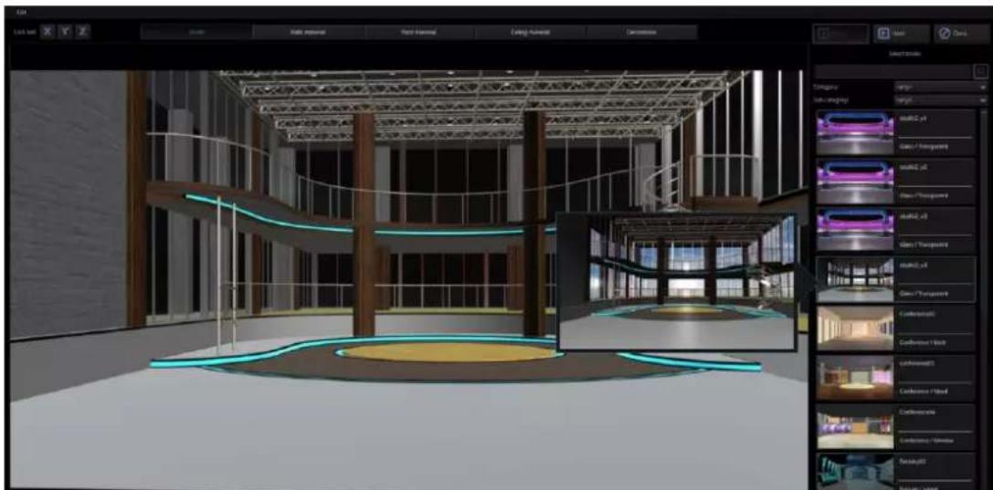
natural_image
3D architectural rendering of a modern building interior with curved structural elements and glowing green lighting (no visible text or symbols)There are several material templates that can be found in the right pane of the 3D Studio Editor. The user will be allowed to select and apply the material template to the wall, floor, and ceiling.
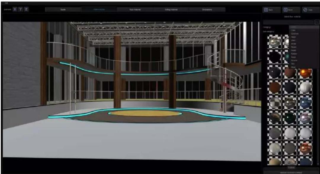
natural_image
3D architectural rendering of a modern building interior with curved railings and a central circular plaza (no visible text or symbols)If users want to restore the material of the object back to the default value, please press the "Restore material to default" button, and then the material in the selected object material page will be restored to the default value.
After clicking the "Wall" tab, click a reflective material in the right pane. Below is the resulting effect after the reflective material is applied.
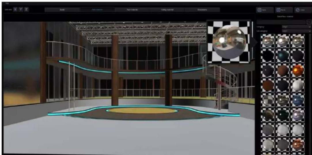
natural_image
3D architectural rendering of a modern building interior with curved railings and a central circular structure, displayed within a software interface (no text or symbols on the scene itself)After clicking the “Decorations” tab, the user will be allowed to add accessory objects such as table, chair, light, TV, podium and etc. In this way, the scene will not look empty. The added accessories should meet the scene requirements of your video production.
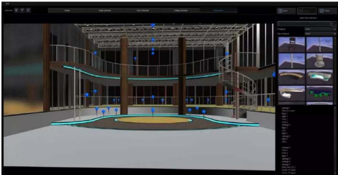
natural_image
3D architectural rendering of a modern multi-level building with curved railings and a central circular structure, displayed in a design software interface (no readable text or symbols on the model itself)How to add an accessory object?
The TVS-2000A provides slots in the Wizard, when users open the Wizard by its Step by Step instructions, the Slots will be shown. Slots are location points that the objects can be added. Slots are used to help users to add their desired objects to the desired positions in the virtual scene. In the scene, click a “Slot” icon and you will immediately see the selected slot flashing, indicating that the slot will be the position at which the object will be placed. In the template area, the user will also be recommended the appropriate objects. The system default of this position is the podium. Of course the user should not be limited by the system default and is allowed to add any object to this position. If all of the desired objects are added into the scene, please press x on the top right side to close the Window and then those objects will appear in the virtual scene.
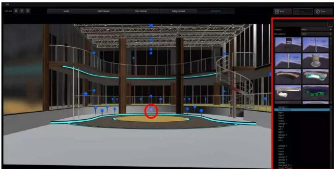
natural_image
3D architectural model of a multi-level building interior with staircases and curved structural elements, displayed in a design software interface (no readable text or symbols on the model itself)How to remove an accessory object
If users want to remove the accessory object, please follow following steps.
Step 1: Please click the accessory object that must be removed. (Take Desk as an example)
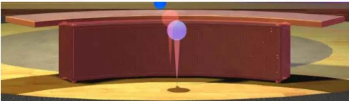
natural_image
Illustration of a red rectangular container with a purple liquid droplet on its side, placed on a yellow circular platform (no text or symbols)Step 2: Please click the button "Remove decoration from placeholder", and then the selected object will be removed from the selected placeholder.

Accessory Object Search
The user is allowed to search the system for the category of the objects to be added. The system provides the user with categories such as ceiling, chairs, columns, desks, floor and lamps, which can be quickly selected by the user.
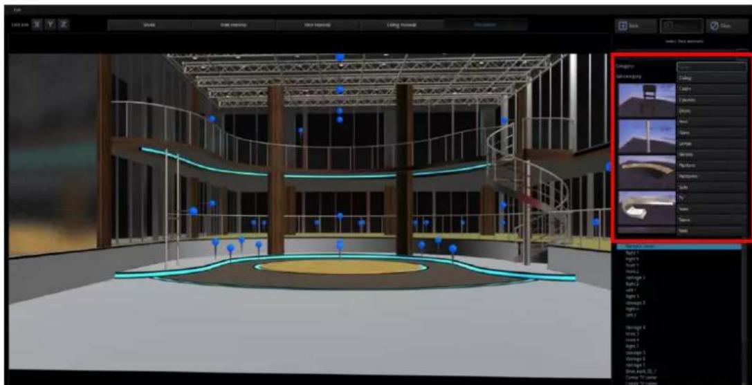
natural_image
3D architectural rendering of a modern building interior with staircases and circular structure, displayed in a design software interface (no readable text or symbols on the model itself)How to change the position of an accessory object?
The following example illustrates how a podium can be added. The user is allowed to enter the relevant values on the control panel in the right half of the screen to modify the object position, rotation and scale. Because the object position is defined by three axes, the XYZ coordinates should be the same to achieve equal zoom ratio.
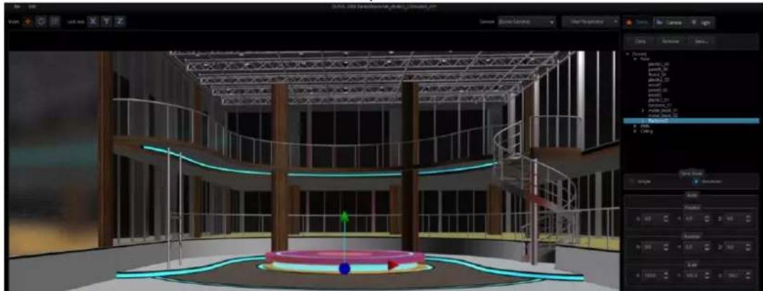
natural_image
3D architectural rendering of a multi-level building with curved staircases and a central platform, displayed in a design software interface (no readable text or symbols on the model itself)If the name of the added object does not appear, please enable the “Advanced” view mode to view the object information.
![Camera Light Close Remove Save... + [Scene] Power pixels2_00 pixels8_01 pixels2_01 pixels2_02 pixels8_03 pixels8_04 pixels2_05 pixels2_06 pixels2_07 pixels2_08 pixels2_09 pixels2_10 pixels2_11 pixels2_12 pixels2_13 pixels2_14 pixels2_15 pixels2_16 pixels2_17 pixels2_18 pixels2_19 pixels2_20 pixels2_21 pixels2_22 pixels2_23 pixels2_24 pixels2_25 pixels2_26 pixels2_27 pixels2_28 pixels2_29 pixels2_30 pixels2_31 pixels2_32 pixels2_33 pixels2_34 pixels2_35 pixels2_36 pixels2_37 pixels2_38 pixels2_39 pixels2_40 pixels2_41 pixels2_42 pixels2_43 pixels2_44 pixels2_45 pixels2_46 pixels2_47 pixels2_48 pixels2_49 pixels2_50 pixels2_51 pixels2_52 pixels2_53 pixels2_54 pixels2_55 pixels2_56 pixels2_57 pixels2_58 pixels2_59 pixels2_60 pixels2_61 pixels2_62 pixels2_63 pixels2_64 pixels2_65 pixels2_66 pixels2_67 pixels2_68 pixels2_69 pixels2_70 pixels2_71 pixels2_72 pixels2_73 pixels2_74 pixels2_75 pixels2_76 pixels2_77 pixels2_78 pixels2_79 pixels2_80 pixels2_81 pixels2_82 pixels2_83 pixels2_84 pixels2_85 pixels2_86 pixels2_87 pixels2_88 pixels2_89 pixels2_90 pixels2_91 pixels2_92 pixels2_93 pixels2_94 pixels2_95 pixels2_96 pixels2_97 pixels2_98 pixels2_99 pixels3_00 Advanced](/content/2026/05/998455/images/b6de2705c8aeed9aaaa9157bb55ea480cf4997108dda75b22949103a0fc58f56.jpg)
Clicking "V" allows the user to view objects in the category. By clicking the sub-category, the user will be allowed to change the object's material property by selecting the material ball right below. If the selected material ball is not the right effect, simply click the "Restore material to default" button at the bottom to reset the material to default.
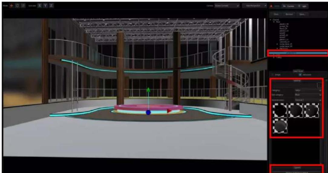
natural_image
3D architectural rendering of a modern building interior with spiral staircase and central circular structure (no visible text or symbols)When all of the settings are done for the Studio Wizard, users can press the Close key to any levelise the Studio Wizard.
Chapter 8 Sound mixer
The TVS-2000A comes equipped with a sound mixer function, which serves to mix sound signals. It also allows the user to adjust the signal level for each source separately as well as the sound output.
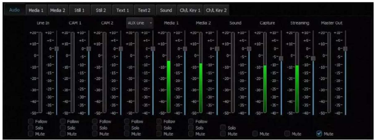
The sound mixer allows the user to adjust the following channels:
- Line IN (3.5 mm Phone Jack) – an external input channel (stereo analogue input on the input card).
• CAM 1 – audio input channel of camera 1.
• CAM 2 – audio input channel of camera 2. - AUX Line – audio input channel of AUX input.
- Media1 – an input channel from files played by the virtual player supported by the Media1 Bin tab.
- Media2 – an input channel from files played by the virtual player supported by the Media2 Bin tab.
• Sound – Audio level of the audio file imported from the disk (Audio Bin tab).
• Capture – the TVS-2000A system captured audio input. - Streaming – audio output of the streaming channel.
- Master Out – an audio output channel.
The signal level for each channel can be set with a slider next to the signal level bar. Additionally, a separate Master Out slider can be used to set the output signal level. The Master Out slider is also displayed next to the Program window. Sound can be adjusted from -40 dB to +10 dB. The 0 level corresponds to -10 dBV (-7.8 dBu or 0.316 V RMS).
Also, the following functions can be turned on for each input channel:
- Follow – This function mutes the sound of the selected channel until the video signal associated with the sound source comes on air. This is related to Media1, Media2, and the CAM source associated with Line IN. Switching on this function with a selected channel causes the sound of a given source to be muted if the source is not streamed (shown) to the PGM output.
- Solo – This function sends the selected signal to the output separately. Switching on this function with a selected channel causes the other input channels to be muted. Only the signal for which the SOLO function has been enabled is sent to the outputs.
- Mute – This function completely mutes the signal for a given source.
Chapter 9 How to Use Acronis True Image for a One-Click Recovery
When the TVS-2000A system is unstable, you can use a built-in system recovery tool to solve this issue.
- Please go to desktop of your Windows OS to find the "Acronis True Image" software. Please click the following icon to open the Acronis software.
- After the Acronis True Image software is opened, please click the "RECOVER DISKS" button which is shown in the following diagram.
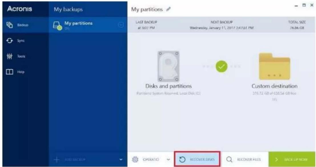
- Click "Recover specific partitions" and the disk that the system has backed up in sequence, and then click RECOVER NOW.
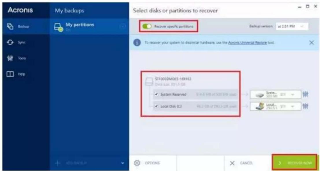
- Please click the "Restart" button.
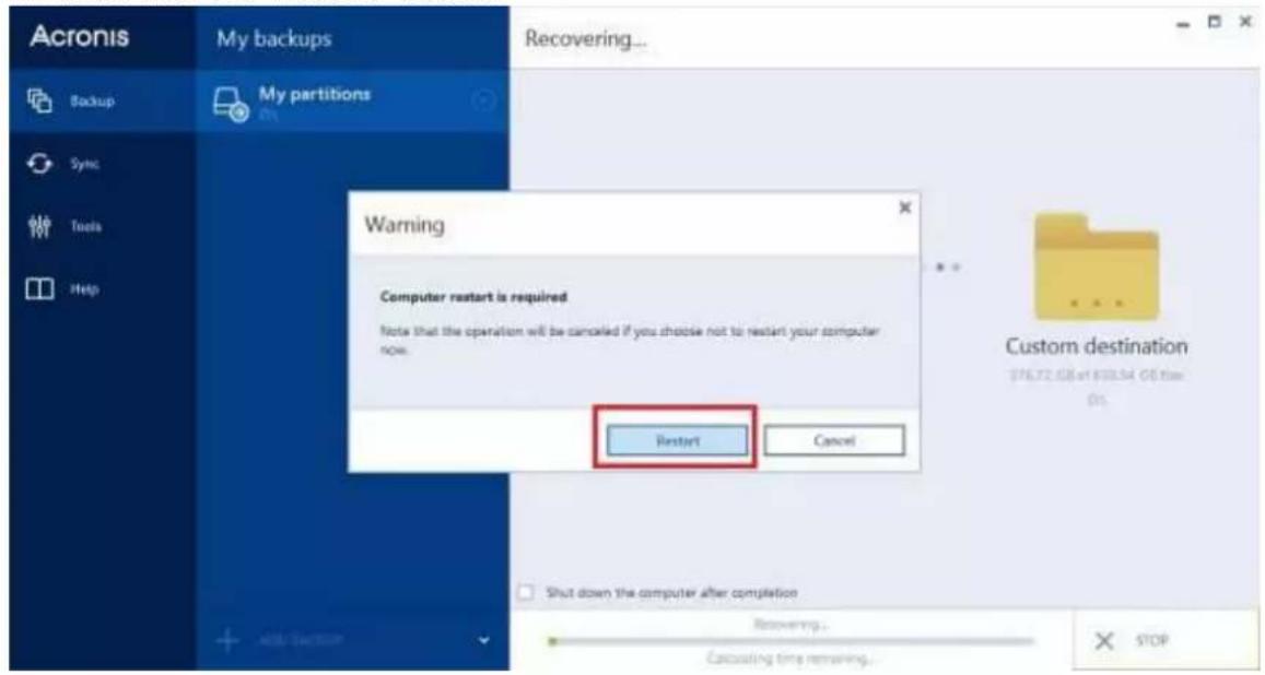
- Your TVS-2000A will reboot automatically and then it will enter the screen which is shown in the following diagram.
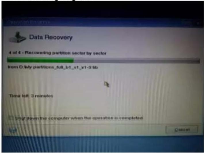
- After the recovery procedure is done, please reboot your computer and please confirm whether the system and the TVS software are operated normally.
Chapter 10 Frequently-Asked Questions
This section describes problems that you may encounter while using the TVS-2000A. If you have questions, please refer to related sections and follow all the suggested solutions. If problem still exists, please contact your distributor or the service center.
| No. | Problems | Solutions |
| 1 | .avi files cannot be played in Media 1/2. | The TVS-2000A does not support avi format. |
| 2 | Still pictures and texts cannot be previewed in Still 1/2 and Text 1/2. | This only occurs occasionally and files can still be opened. |
| 3 | Why does the TVS system exit to Windows desktop right after monitor cable is unplugged while TVS system is running? | TVS system has to work with monitors connected, please do not unplug monitor while the TVS system is still running. |
| 4 | Why the Windows Media Player cannot play the MPEG file captured using the TVS system? | Please use VLC Player, which is a freeware. Windows Media Player cannot play MPEG II files. |
| 5 | Why, after renaming the captured file in the TVS system, the file name on the Windows OS remains unchanged? | The TVS system only allows local renaming of the captured files during any TVS session, and does not rename the actual file name on the PC system. This is because a single file can be referenced by many other projects or sessions so if the actual file name on the PC system is renamed, the reference to other projects/sessions will be lost. |
| 6 | After “Follow” is enabled for Line IN on the TVS audio mixer, the Line IN audio is found to output with CAM1 or CAM2. | The Line in will follow Cam1 or Cam2 after the “Follow” check box is checked. If you do not want the Line in Audio, please select Mute for Line in. |
| 7 | Why does the screen viewable area become smaller right after bootup of the TVS machine? | This may happen in some monitors. Please activate overscan mode of the monitor. |
| 8 | Why are there warning signs on my multi-viewer? | Please make sure all the resolutions and frame rate are same as your session resolution and frame rate which you assigned on the startup menu before production. |
| 9 | I cannot hear audio output from the TVS-2000A PGM OUT while the output is set to 1080P 50/60, however, I can see the video. | If your output is set to 1080P 50/60, please make sure the SDI 3G output mapping (Configuration / Configuration / General) is correctly selected (Type A or Type B). |
| 10 | The order of the three monitors is not the order that I want. | Please adjust the monitor order in the TVS Monitor configuration settings. (Configuration / Configuration / screens / monitor configuration) |
| 11 | What codec should I use if I want to create a downstream key that has an animation effect with Alpha Channel? | Please use Lagarith Lossless to make .avi file, or DNxHD to make .mov file. Please make sure to select RGBA format which includes Alpha Channel. |
| 12 | Why is there no sound from Aux card (Green card) HDMI output? | Aux Card for PVW output does not include audio. The PGM output supports Audio embedded. |
| 13 | Why is there no video out while feeding the Aux card (Green Card) HDMI output with 1080P 50 / 59.964 / 60 inputs? | Aux Card does not support 1080P 50 / 59.964 / 60 format. Please use lower resolution format. |
| 14 | Why is there only 2 audio channel output when I use an 8 audio channel input? | TVS supports 2 audio channels only. |
| 15 | How to monitor the PGM audio? | The user can use a TV or a monitor with earphone connector or speaker and connect it to PGM OUT. |
| 16 | Can I place a 3D object (ex: a virtual desk) in front of the tracking camera source, and do tracking? | No, the Tracking source will be the top layer of the tracking V/C. All the other 3D virtual element will stay behind it. The way to put talent behind a virtual desk is by trackless. |
| 17 | What things should I pay attention to when performing the One-Click Recovery? | Due to the new hardware version (motherboard with Z690 chipset) of the TVS-2000A, you need to modify the BIOS settings in advance in order to perform the “One-Click Recovery” successfully.Note: Before using the ACRONIS software, you need to enter BIOS’ Advance Mode and then set the “BOOT CSM” option as “Enable”. After that, you can go back to your system to use the Acronis software to do the “One-Click Recovery”. After the “One-Click Recovery” procedure is finished, please enter BIOS’ Advance Mode again, and thenPlease set the “BOOT-CSM” option as “Disable”.Please set “Advanced>System Agent Configuration>Graphics Configuration>iGPU Multi-monitor” as “Enable”. |
Chapter 11 Specifications
| Model Name | TVS-2000A |
| Product Name | Tracking Virtual Studio System |
| Tracking/Trackless | Tracking & Trackless (It can support up to 2 tracking cameras simultaneously (pan/tilt/zoom tracking can be used only when using Datavideo PTC-150 camera). |
| Video Input | 3G-SDI x 2 + AUX-HDMI x 1 |
| Video Output | 3G-SDI x 2 + AUX-HDMI x 1IP Stream: RTMP x 1 |
| Video Input Format | SDI1080p 60/59.94/50/30/29.97/251080i 60/59.94/50720p 60/59.94/50HDMI1080i 60/59.94/50720p 60/59.94/50 |
| Video Output Format | SDI1080p 60/59.94/50/30/29.97/251080i 60/59.94/50720p 60/59.94/50HDMI1080i 60/59.94/50720p 60/59.94/ 50 |
| Audio Input | Mini Phone Jack x 2 ( 1x on motherboard, 1x on virtual card)HDMI audio embedded x 1SDI audio embedded x 2 |
| Operation Monitor | DP x2, HDMI x2, DVI x1 (Choose 3 from 5) |
| Tally | Yes |
| Downstream Key | 2 |
| Media | 2 (DDR) |
| Virtual Studio | 112 x 3D Virtual Sets45 x 3D Virtual Set Templates223 x 3D DecorationUnlimited download fromdatavideovirtualset.com |
| Still Picture | 2 |
| Still Text | 2 |
| Keyer | Chromakey / Luminance key x 2 |
| Recording | H.264 / MPEG-2 |
| Live Streaming Protocols | FLV RTMP |
| PTZ Control Protocol | VISCA over RS-422 |
| Hard Disk Capacity | 1TB+240G SSD |
| Dimension(L x W x H) | 480 x 470 x178mm |
| Weight | 13.6kg |
| Operating Temp. Range | 0°C~40°C |
| Power | AC 100-240V 550W |
| TVS Virtu Aux Card | |
| Video Input | HDMI x 1 |
| Video Output | HDMI x 1 (Preview without audio) |
| Video Input Format | 1080 30P / 29.97P / 25P1080 60i / 59.94i / 50i720 60P / 59.94P / 50P |
| Audio Input | Mini Phone Jack x 1HDMI audio embedded |
Note
Note
Note
Service & Support
It is our goal to make owning and using Datavideo products a satisfying experience. Our support staff is available to assist you to set up and operate your system. Contact your local office for specific support requests. Plus, please visit www.datavideo.com to access our FAQ section.
Please visit our website for latest manual update.
https://www.datavideo.com/product/TVS-2000A
datavideo
www.datavideo.com

@DatavideoUSA @DatavideoIndia2016
@DatavideoEMEA @Datavideojapan
@DatavideoTaiwan @DatavideoLatam
@DatavideoAsia @DatavideoBrasil

@DatavideoUSA
@DVTWDVCN

@Datavideo
@Datavideo EMEA
@Datavideo Taiwan

@DatavideoUSA
@DatavideoEurope
- WARNINGS AND PRECAUTIONS 4
- WARRANTY....5
- DISPOSAL....5
- CHAPTER 1 OVERVIEW 7
- CHAPTER 2 TVS-2000A TRACKING VIRTUAL STUDIO SETUP 9
- CHAPTER 3 STARTING TVS-2000A SOFTWARE....25
- CHAPTER 4 PRODUCTION LIVE SCREEN 28
- CHAPTER 5 CHROMA AND LUMA KEYS .... 50
- CHAPTER 6 FAST CHROMAKEYING....60
- CHAPTER 7 3D STUDIO EDITOR....61
- CHAPTER 8 SOUND MIXER....86
- CHAPTER 9 HOW TO USE ACRONIS TRUE IMAGE FOR A ONE-CLICK RECOVERY 87
- CHAPTER 10 FREQUENTLY-ASKED QUESTIONS....89
- CHAPTER 11 SPECIFICATIONS....91
- SERVICE & SUPPORT 96
- Disclaimer of Product and Services
- FCC Compliance Statement
- Warnings and Precautions
- Warranty
- Standard Warranty
- Three Year Warranty
- Disposal
- For EU Customers only - WEEE Marking
- CE
- Chapter 1 Overview
- Features
- Varieties of System Inputs with Front Object Integration:
- Additional Media Features
- Virtual Background Features
- Media Previews
- Supported Formats
- Video Processing Formats
- Other Miscellaneous Features
- Chapter 2 TVS-2000A Tracking Virtual Studio Setup
- System Requirement
- Connections
- Front Panel
- Back Panel
- Power Supply Socket
- Power On/Off Switch
- RS-232 Connection
- USB 3.x Type A Port
- USB 3.x Type C Port
- Wi-Fi 6 SMA Interface
- LAN (RJ-45) Port
- LINE OUT Interface
- Input/Output Card Options
- Display Card
- Note:
- Tracking Camera Control Card (Purple)
- Virtu AUX Card (Green)
- RMC-280 Remote Controller
- Main Unit - Rear Panel
- Program and Preset rows
- Preview and Program Switching
- TAKE
- Cross-Dissolve
- FTB
- Rolling Wheel (T-Bar)
- Downstream Keyers
- DSK 1/2
- Control Knob
- Cut
- AUTO TRANS
- Function Keys
- F1-F10
- Stream
- Capture
- Still/Grab
- P1 - P10
- Linear and Curved
- Joystick
- ZOOM Wheel
- LOCK
- FOCUS Knob
- IRIS/ENTER Knob
- AUTO White Balance
- Speed
- CAM 1/2
- Camera Lens Positions
- Keyboard Backlight
- RMC-280 Calibration Process
- How to Calibrate the PTC-150 Camera Position for Your TVS-2000A System
- Chapter 3 Starting TVS-2000A Software
- Production Live
- Still Text Edit
- TVS News link
- VIRTUALSET Shop
- Shutdown
- Configuration
- Chapter 4 Production Live Screen
- Tool Bar
- File
- Options
- Layout
- Language
- Configuration
- Help
- Multi-View Area
- Program and Preview Rows & Function Settings
- 11-input Main Switcher
- Switching between Preview and Program Views
- Downstream Keys
- Scene Editing
- Camera Setup
- Position
- Rotation
- ZOOM
- Linear and Curved Auto Play
- File Management
- Triggers – RMC-280 Function Keys
- Advanced
- Simple
- Monitor Configuration
- General Display and Audio Settings
- Motion Capture Specification
- Program Video Stream
- Tracking Cameras
- Chapter 5 Chroma and Luma Keys
- Key Selection
- Chroma Key
- Matte Control
- Tolerance Correction
- A view 'before' and 'after'
- Spill Correction
- Edge Correction
- Garbage Mask
- Post Correction
- Chapter 6 Fast Chromakeying
- Simple Chroma Key
- Wizard
- Chapter 7 3D Studio Editor
- Open the 3D Studio Editor
- Studio Editor Overview
- Virtual Scene and Light Customization Tool
- All direction
- "Lock Axis" Mode
- View of the Scene
- Virtual Set Object Selection
- Scene
- SKYBOX
- Cylinder
- Sphere
- Sphere Reflect
- How to modify properties of a 3D object?
- How to restore the material of the 3D object?
- Camera
- Camera Position, Rotation and Zoom
- Light
- Ambient Light
- Directional
- Point
- Spot
- Studio 3D Editor Wizard
- Virtual Camera Customization Tool
- Wizard
- Scene Objects
- How to add an accessory object?
- How to remove an accessory object
- Accessory Object Search
- How to change the position of an accessory object?
- Chapter 8 Sound mixer
- Chapter 9 How to Use Acronis True Image for a One-Click Recovery
- Chapter 10 Frequently-Asked Questions
- Service & Support
Brand : DataVideo
Model : TVS-2000A
Category : Alarm system