
RGV13100T - Generator SUBARU - Free user manual and instructions
Find the device manual for free RGV13100T SUBARU in PDF.


| Type de produit | Generator |
| Marque | Subaru |
| Modèle | RGV13100T |
| Puissance maximale | 13100 W |
| Puissance nominale | 11800 W |
| Tension | 120/240 V |
| Fréquence | 60 Hz |
| Type de moteur | 4-stroke, OHV, single cylinder |
| Cylindrée | 720 cc |
| Réservoir de carburant | 38 L |
| Autonomie à 50% charge | 12 hours |
| Système de démarrage | Electric start with recoil backup |
| Type de carburant | Gasoline |
| Niveau sonore à 7m | 74 dB(A) |
| Dimensions (L x l x H) | 950 x 620 x 650 mm |
| Poids | 185 kg |
| Type d'alternateur | Brushless, synchronous |
| Prises | 2x 120V 20A, 1x 120/240V 30A twist lock, 1x 12V DC |
| Caractéristiques | AVR, low oil shutdown, overload protection, fuel gauge, wheel kit, hour meter |
| Entretien moteur | Oil change every 50h, air filter cleaning every 100h, spark plug every 200h |
| Reparabilité | Spare parts available, easy access to engine and alternator |
| Sécurité | GFCI on outlets, spark arrestor muffler |
| Certifications | EPA, CARB |
Frequently Asked Questions - RGV13100T SUBARU
User questions about RGV13100T SUBARU
0 question about this device. Answer the ones you know or ask your own.
Ask a new question about this device
Download the instructions for your Generator in PDF format for free! Find your manual RGV13100T - SUBARU and take your electronic device back in hand. On this page are published all the documents necessary for the use of your device. RGV13100T by SUBARU.
USER MANUAL RGV13100T SUBARU
natural_image
Line drawing of a portable industrial power supply unit with control panel and wheels (no text or symbols)3ZZ9020236
DANGER
Using a generator indoors CAN KILL YOU IN MINUTES.
Generator exhaust contains carbon monoxide. This is a poison you cannot see or smell.
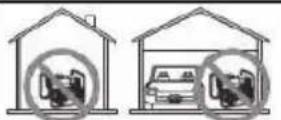
NEVER use inside a home or garage, EVEN IF doors and windows are open.
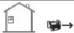
Only use OUTSIDE and far away from windows, doors, and vents.
WARNING:
The engine exhaust from this product contains chemicals known to the State of California to cause cancer, birth defects or other reproductive harm.
(California only)
AIR INDEX
To show compliance with California emission regulations, a hangtag has been provided displaying the Air Index level and durability period of this engine.
The Air Index level defines how clean an engine's exhaust is over a period of time. A bar graph scaled from "0" (most clean) to "10" (least clean) is used to show an engine's Air Index level. A lower Air Index level represents cleaner exhaust from an engine.
The period of time (in hours) that the Air Index level is measured is known as the durability period. Depending on the size of the engine, a selection of time periods can be used to measure the Air Index level (see below).
Descriptive Term Applicable to Emissions Durability Period
Moderate - 50 hours (engine from 0 to 80 cc) 125 hours (engine greater than 80 cc)
Intermediate - 125 hours (engine from 0 to 80 cc) 250 hours (engine greater than 80 cc)
Extended - 300 hours (engine from 0 to 80 cc) 500 hours (engine greater than 80 cc) 1000 hours (225 cc and greater)
Notice: This hangtag must remain on this engine or piece of equipment, and only be removed by the ultimate purchaser before operation.
Notice : FEDERAL EMISSION COMPONENT DEFECT WARRANTY and CALIFORNIA EMISSION CONTROL WARRANTY are applicable to only those engines/ generators complied with EPA (Environmental Protection Agency) and CARB (California Air Resources Board) emission regulations in the U.S.A.
Notice : To the engines/generators exported to and used in the countries other than the U.S.A., warranty service shall be performed by the distributor in each country in accordance with the standard SUBARU engine/generator warranty policy as applicable.
FOREWORD
Thank you very much for purchasing a SUBARU GENERATOR.
This manual covers operation and maintenance of the SUBARU GENERATOR.
This SUBARU GENERATOR can be used for general electrical equipments, appliances, lamps, tools as an AC power source. With regards to DC application, the terminals are used only for charging 12 volt battery.
Never use this generator for any other purposes.
Please take a moment to familiarize yourself with the proper operation and maintenance procedures in order to maximize the safe and efficient use of this product.
Keep this owner's manual at hand, so that you can refer to it at any time.
Due to constant efforts to improve our products, certain procedures and specifications are subject to change without notice.
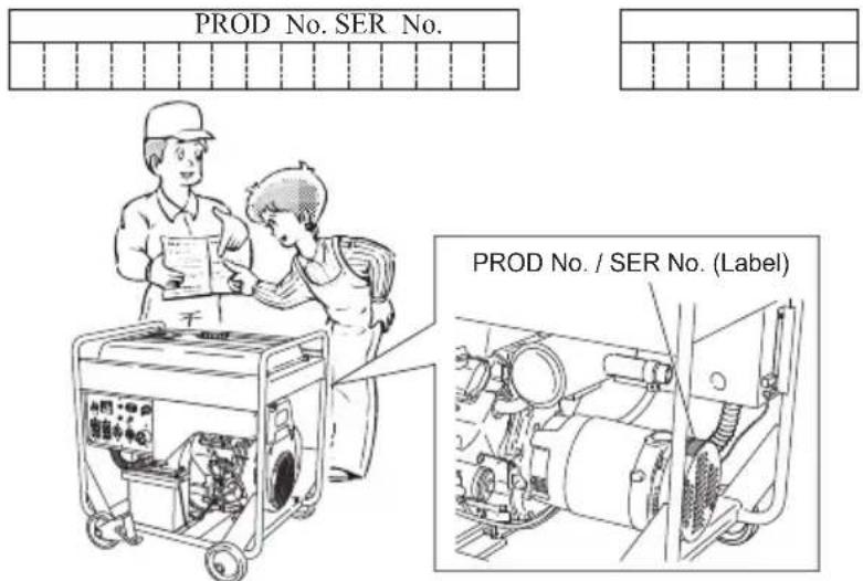
When ordering spare parts, always give us the MODEL, PRODUCTION NUMBER (PROD No.) and SERIAL NUMBER (SER No.) of your Product.
Please fill in the following blanks after checking the production number on your product. (Location of label is different depending on the product model.)
CONTENTS
-
SAFETY PRECAUTIONS .... 1
-
SPECIFICATIONS.... 4
-
COMPONENTS 5
-
PRE-OPERATION CHECKS. 6
-
OPERATING PROCEDURES ...... 11
6.WATTAGE INFORMATION 24
-
SPARK ARRESTER 26
-
MAINTENANCE SCHEDULE 27
-
"HOW-TO" MAINTENANCE 29
-
PREPARATION FOR STORAGE 34
-
TROUBLESHOOTING.... 35
-
WIRING DIAGRAM 36
13.OPTIONAL PARTS 38
Symbols and Meanings
In accordance with the European requirements (eec Directives), the specified symbols as shown in the following table are used for the products and this instruction manual.
 | Read the operator's instruction manual. |  | Fire, open light and smoking prohibited. |
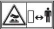 | Stay clear of the hot surface. |  | Do not connect the generator to the commercial power lines. |
 | Exhaust gas is poisonous.Do not operate in an unventilated room. |  | Do not operate in rain or snow. |
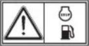 | Stop the engine before refueling. |  | Call for maintenance. |
 | Caution, risk of electric shock. |  | Keep dry. |
 | HOT, avoid touching the hot area. |
| USA and CANADA only | |||||
 | Read INSTRUCTIONS FOR USE before use. |  | The engine emits toxic gas can kill you in minutes.Do not run in an enclosed area. |  | Hot surface can burn you.Stay away if engine has been running. |
| Gasoline is extremely flammable and its vapors can explode.Stop the engine before refueling.Check for leakage from hoses and fittings.Shut off fuel valve when the engine is not in use. | |||||
 | ON(power and Engine) |  | IN-position of a bistable push control | [wTC8] | Engine start (Electric start) |
 | OFF(power and Engine) |  | Protective earth (ground) |  | Engine stop |
 | Alternating current |  | Fuse |  | Gasoline |
 | Direct current |  | Engine oil |  | Fast |
 | Plus ; positive polarity |  | Add oil |  | Slow |
 | Minus ; negative polarity |  | Battery charging condition |  | Fuel start / Open |
 | OUT-position of a bistable push control |  | Choke ; cold starting aid |  | Fuel stop / Close |
| P_r | Rated power (kW) | COP | Continuous power | COS_r | Rated power factor |
| f_r | Rated frequency (Hz) | U_r | Rated voltage (V) | I_r | Rated current (A) |
| H_max | Maximum site altitude above sea-level (m) | T_max | Maximum ambient temperature (°C) | m | Mass (kg) |
1. SAFETY PRECAUTIONS
Please make sure you review each precaution carefully.
Pay special attention to statement preceded by the following words.

DANGER
"DANGER" indicates a possibility of death or serious injury if instructions are not followed.

WARNING
"WARNING" indicates a strong possibility of severe personal injury or loss of life if instructions are not followed.

CAUTION
"CAUTION" indicates a possibility of personal injury or equipment damage if instructions are not followed.

WARNING
Do not operate the generator near gasoline or gaseous fuel because of the potential danger of explosion or fire.
Do not fill the fuel tank with fuel while the engine is running. Do not smoke or use open flame near the fuel tank. Be careful not to spill fuel during refueling.
If fuel is spilt, wipe it off and let dry before starting the engine.

WARNING
Do not place in flammables near the generator.
Be careful not to place fuel, matches, gunpowder, oily cloths, straw, trash, or any other in flammables near the generator.

WARNING
Do not operate the generator inside a room, cave, tunnel, or other insufficiently ventilated area.
Always operate it in a well-ventilated area, otherwise the engine may become overheated, and the poisonous carbon monoxide gas, an odorless, colorless, poison gas, contained in the exhaust gas will endanger human lives.
Operate generator only outdoors and far from open windows, doors, ventilation intakes and other openings.
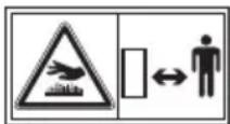
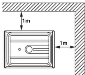
Keep the generator at least 1 meter (3 feet) away, including overhead, from any structure or building use.

WARNING
Do not enclose the generator nor cover it with a box.
The generator has a built-in forced air cooling system, and may become overheated if it is enclosed.
If generator has been covered to protect it from the weather during non use, be sure to remove it and keep it well away from the area during generator use.

WARNING
Operate the generator on a level surface.
It is not necessary to prepare a special foundation for the generator.
However, the generator will vibrate on an irregular surface, so choose a level place without surface irregularities.
If the generator is tilted or moved during operation, fuel may spill and / or the generator may tip over, causing a hazardous situation.
Proper lubrication cannot be expected if the generator is operated on a steep incline or slope. In such a case, piston seizure may occur even if the oil is above the upper level.

WARNING
Pay attention to the wiring or extension cords from the generator to the connected device.
If the wire is under the generator or in contact with a vibrating part, it may break and possibly cause a fire, generator burnout, or electric shock hazard.
Replace damaged or worn cords immediately.

WARNING
Do not operate in rain, in wet or damp conditions, or with wet hands.
The operator may suffer severe electric shock if the generator is wet due to rain or snow.

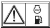
WARNING
If wet, wipe and dry it well before starting. Do not pour water directly over the generator, nor wash it with water.
WARNING
Be extremely careful that all necessary electrical grounding procedures are followed during each and every use. Failure to do so can be fatal.
WARNING
Do not contact the generator to a commercial power line. Connection to a commercial power line may short circuit the generator and ruin it or cause electric shock hazard. Use the transfer switch for connecting to domestic circuit.

WARNING
No smoking while handling the battery. The battery emits flammable hydrogen gas, which can explode if exposed to electric arcing or open flame. Keep the area well-ventilated and keep open flames/sparks away when handling the battery.

WARNING
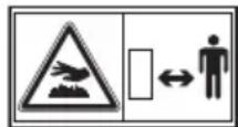
Engine becomes extremely hot during and for some time after operation.
Keep combustible materials well away from generator area.
Be very careful not to touch any parts of the hot engine especially the muffler area or serious burns may result.
WARNING
Keep children and all bystanders at a safe distance from work areas.
WARNING
It is absolutely essential that you know the safe and proper use of the power tool or appliance that you intend to use. All operators must read, understand and follow the tool/appliance owners manual. Tool and appliance applications and limitations must be understood. Follow all directions given on labels and warnings. Keep all instruction manuals and literature in a safe place for future reference.
WARNING
Use only "LISTED" extension cords.
When a tool or appliance is used outdoors, use only extension cords marked "For Outdoor Use". Extension cords, when not in use should be stored in a dry and well ventilated area.
WARNING
Always switch off generator's AC circuit breaker and disconnect tools or appliances when not in use, before servicing, adjusting, or installing accessories and attachments.
CAUTION
Make sure the engine is stopped before starting any maintenance, servicing or repair.
Make sure maintenance and repair of the generator set are performed by properly trained personnel only.
CAUTION : PRECAUTIONS ON THE HANDLING OF THE WARNING LABEL
Warning labels are affixed to our engines with regard to particularly serious dangers.
When using the engines, please use them safely after carefully reading the instruction manual and understanding the dangers.
Warning Label Exclusively for the United States and Canada
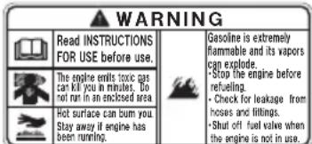
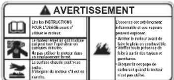
For use in the United States or Canada, please affix the label suited to the region from among the enclosed warning labels.
Check that following accessories come with your SUBARU Generator.
(1) Instruction for use
(2) Wheel mounting parts (See page 37.)
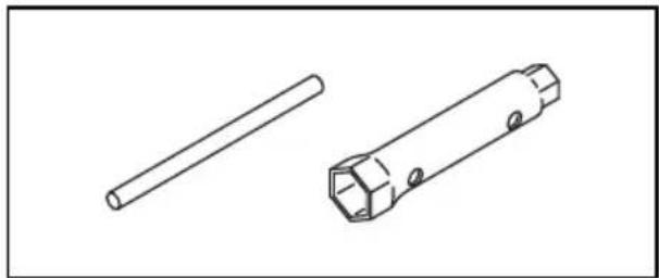
(3) Servicing tools
(4) Battery mounting bracket
(See page 8 and 9.)
natural_image
Technical line drawing of two mechanical components: a cylindrical rod and a rectangular device with mounting holes (no text or symbols)Be sure to replenish with engine oil.
(See page 6 for details.)
Notes on installation
-
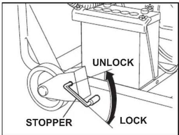
If you provide the generator with wheels, always be sure to place the generator on a level surface, locking the wheel with the stopper and/or chocking the wheels.
-
Select a place which allows you to maintain and inspect the generator, which is not exposed to contamination caused by exhaust gas.
If you are planning to install the
generator without its wheels attached, consider the work efficiency in terms of an oil change.
-
In ground connection, be sure to use the designated ground terminal. (A grounding cable is not included in the set of accessories.)
-
During use, be sure not to disconnect the battery.
-
While the power is on, do not unplug the unit or disconnect cables from the terminals.
2. SPECIFICATIONS
| MODEL RGV12100 RGV13100T | ||||
| Alternator | Type | Brush, Self-exciting, 2-pole, Single-phase | Brush, Self-exciting, 2-pole, 3-phase | |
| Rated frequency 60 Hz | ||||
| Rated voltage 120V / 240V | 120V / 208V | |||
| Maximum output 12000 VA | 13000 VA | |||
| Rated output 9500 VA 10000 VA | ||||
| Rated power factor 1.0 0.8 | ||||
| Voltage regulator A.V.R type C.T. type | ||||
| Engine | Model EH65D | EH63D | ||
| Type | Twin cylinder, Air-cooled, 4-stroke, Overhead valve engine | |||
| Displacement | 653 mL (39.8 cu.in.) | |||
| Fuel | Automotive Unleaded Gasoline | |||
| Oil capacity | 0.41 US-gal /1.55 liters | |||
| Starting system | Electric starter | |||
| Fuel tank capacity | 10.04 US-gal (38 liters) | |||
| Rated continuous operation per a tankful of fuel | Rated | Approx. 7.1 hours | Approx. 7.7 hours | |
| Dimension | Length | 32.5 in. / 826 mm | ||
| Width | 24.1 in. (30.2 in.) / 611 mm (766 mm) *1 | |||
| Height | 30.4 in. (33.7 in.) / 771 mm (856 mm) *1 | |||
| Dry Weight | 141 kg (149 kg) *2 | 143 kg (151 kg) *2 | ||
| Remote controller terminal (Auto choke) | Standard | — | ||
| Valve Clearance (Intake & Exhaust) | 0.0039 ± 0.0008 in. ( 0.1 ± 0.02 mm)Note: Adjust the valve clearance while the engine is cold. | |||
| Emissions Durability Period | 1000 hours | — | ||
Specifications are subject to change without notice.
NOTE
*1: ( ) shows dimensions with castors.
*2: ( ) shows dry weight with castors installed.
3. COMPONENTS
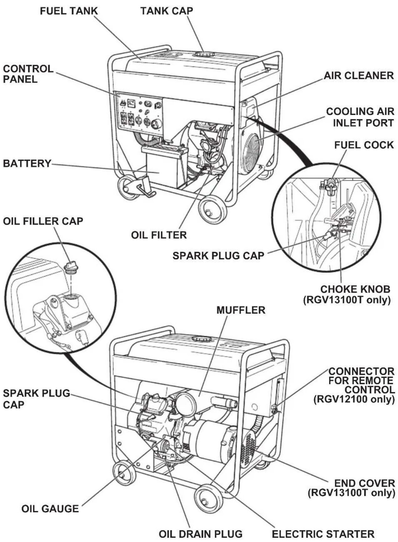
4. PRE-OPERATION CHECKS
CHECK ENGINE OIL
Before checking or refilling oil, be sure generator is located on stable and level surface with engine stopped.
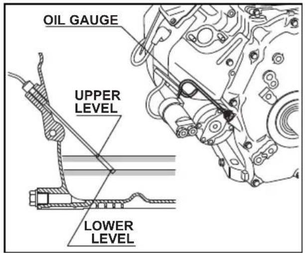
1) Remove oil level gauge and check the engine oil level.
2) If oil level is below the lower level line on the oil gauge, refill with suitable oil (see table) to upper level after removing the engine oil filler cap.
3) Change oil if contaminated. (See "How-To" Maintenance.)
| Oil capacity (Upper level) : L(U.S. gal) | |
| RGV12100 | 1.55 (0.41) |
| RGV13100T | 1.55 (0.41) |
NOTE:
The engine is equipped with an oil sensor unit (hydraulic pressure detection type) that will automatically stop the engine if oil in the crank case is reduced below the specified level. Should the engine be automatically stopped, be sure to check the amounts of fuel and oil.
When the oil is reduced below the specified level, add new oil to the upper limit. Since the oil sensor will not detect the deterioration of oil, visually check the quality or determine it by the specified time and then change the oil if necessary. (Refer to page 28.)
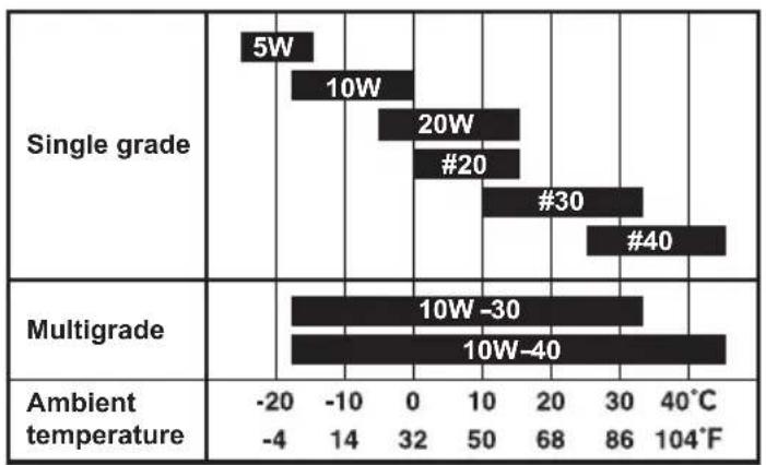
Recommended engine oil:
Use 4-stroke automotive detergent oil of API service class SE or higher grade (SG, SH or SJ is recommended). SAE 10W-30 or 10W-40 is recommended for general, all-temperature use. If single viscosity oil is used, select the appropriate viscosity for the average temperature in your area.
bar
| Category | Temperature Range (°C) | Label | | :--- | :--- | :--- | | Single grade | -20 to 40 | 5W | | Single grade | -10 to 0 | 10W | | Single grade | 0 to 10 | 20W | | Single grade | 10 to 20 | #20 | | Single grade | 20 to 30 | #30 | | Single grade | 30 to 40 | #40 | | Multigrade | -20 to 40 | 10W-30 | | Multigrade | -10 to 0 | 10W-40 | | Ambient temperature | -4 to 104°C | -4 to 14 | | Ambient temperature | 0 to 50 | 32 to 68 | | Ambient temperature | 10 to 20 | 68 to 86 | | Ambient temperature | 20 to 30 | 40°C to 104°F |CHECK ENGINE FUEL.

WARNING
Do not refuel while smoking or near open flame or other such potential fire hazards. Otherwise fire accident may occur.
NOTE : THIS ENGINE IS CERTIFIED TO OPERATE ON AUTOMOTIVE UNLEADED GASOLINE.
Check fuel level at fuel level gauge.
If fuel level is low, refill with automotive unleaded gasoline only.
Use unleaded automotive gasoline only.
- Unleaded regular/premium or reformulated gasoline containing no more than 10% Ethanol (E10), or 15% MTBE may also be used.
- Never use gasoline containing ethanol exceeding 10%, or MTBE exceeding 15% because engine or fuel system damage could result.
- Never use stale or contaminated gasoline.
- Use of these non-recommended fuels may result in reduced performance and/or denial of warranty.
Stop the engine and open the cap.
Close the fuel valve before filling the fuel tank.
Be sure to use the fuel filter screen on the fuel filter neck.
Reattach the fuel cap by turning clockwise until reaching the physical stop (about one quarter turn). Do not attempt to turn past the physical stop or the fuel cap may be damaged.
NOTE :
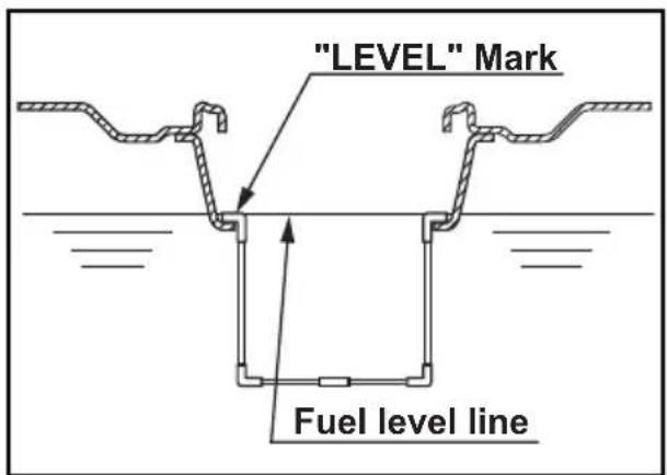
The full level of fuel is the upper surface of the fuel filter.
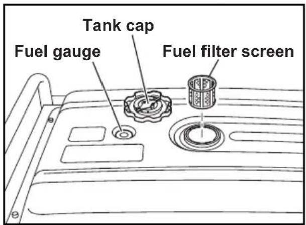
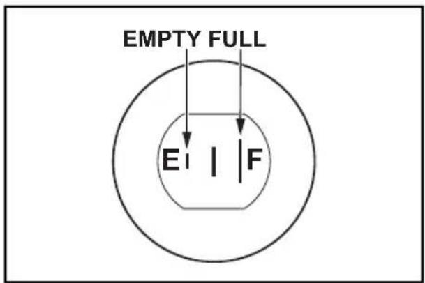
Fuel Amount
up to "LEVEL" position : L (U.S. gal)
RGV12100 ..... 38.0 (10.04)
RGV13100T ..... 38.0 (10.04)
| Continuous operation time in normal use (rated load) | |
| RGV12100 Approx. 7.1 hours | |
| RGV13100T Approx. 7.7 hours |

WARNING
Make sure you review each warning in order to prevent fire hazard.
Do not refill tank while engine is running or hot.
Close fuel cock before refueling with fuel.
Be careful not to admit dust, dirt, water or other foreign objects into fuel.
Do not fill above the top of the fuel filter (marked "LEVEL") or the fuel may overflow when it heats up later and expands.
Wipe off spilt fuel thoroughly before starting engine.
Keep open flames away.
BATTERY INSTALLATION
Recommended Battery
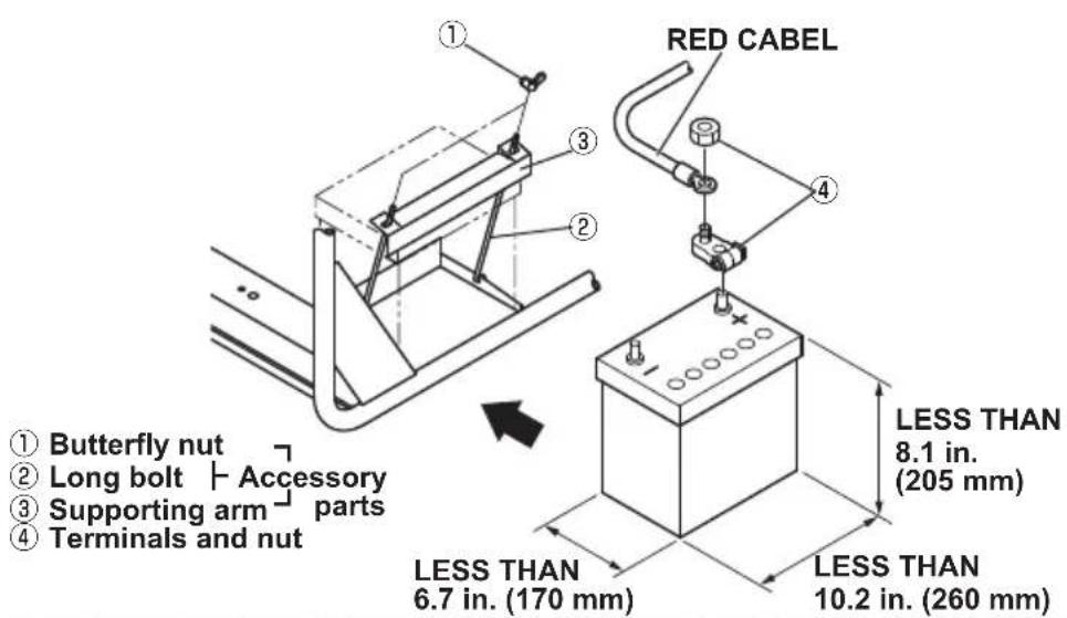
Lead-acid battery : A capacity of 12V-32A•h or larger.
For the generators used in low temperature (below -5°C), 12V-40A·h or larger battery is recommended.
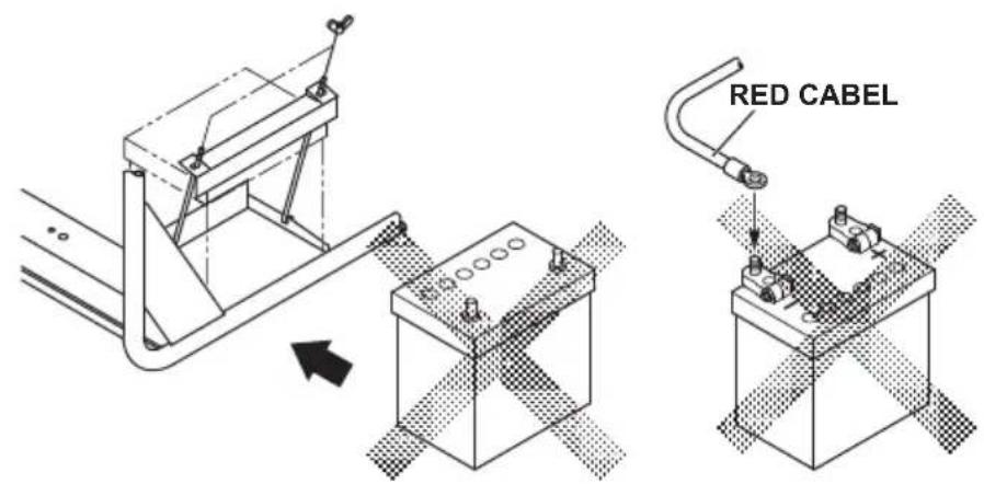
1) Attach terminals to a lead-acid battery already charged. Mount the battery onto the position as specified below, with its terminals facing inward.
2) Insert each long bolt through the specified hole, its tip pointing outward.
3) Put the supporting arm on the long bolts and tighten with the butterfly nuts. (Push the lead-acid battery all the way inward.)
4) Arrange the wiring so that it won't be damaged by possible vibration caused by the engine.
5) Only after checking that the engine's starter key is in the "OFF" position, securely connect the red cable, to the positive (+) terminal. And then connect the other cable to the negative (-) terminal.
Red cable : to the (+) terminal
Black cable : to the (-) terminal
[CAUTION]
Should the connection be made in incorrect manner, the engine will be broken.
![SUBARU RGV13100T - [CAUTION] - 3](/content/2026/05/998228/images/39573d7ba20d264a258a2cc84e88909c19d5050fb7fbccac4f9654fd599c616f.jpg)
WARNING
Death, personal injury and/or property damage may occur unless instructions are followed carefully.
Disconnect battery cables when charging battery.
Use battery of specified capacity listed in the owner's manual.
Turn the starter switch to the "STOP" position when mounting or dismounting battery. Connect positive (+) terminal first when mounting battery, and disconnect negative (-) terminal first when dismounting.
RED CABLE : To positive (+) terminal
BLACK CABLE : To negative ( - ) terminal
CHECK COMPONENT PARTS
Check following items before starting engine:
Fuel leakage from fuel hose, etc.
Bolts and nuts for looseness.
Components for damage or breakage.
Generator not resting on or against any adjacent wiring.
CHECK GENERATOR SURROUNDINGS

WARNING
Make sure you review each warning in order to prevent fire hazard.
Keep area clear of inflammables or other hazardous materials.
Keep generator at least 3 feet (1 meter) away from buildings or other structures.
Only operate generator in a dry, well ventilated area.
Keep exhaust pipe clear of foreign objects.
Keep generator away from open flame. No smoking!
Keep generator on a stable and level surface.
Do not block generator air vents with paper or other material.
5. OPERATING PROCEDURES
STARTING THE GENERATOR
[CAUTION]
Check the oil level before each operations. (See page 6) Perform the specified Daily Inspection to see if it is in normal condition.
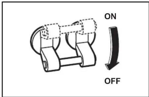
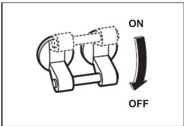
(1) Make sure that the AC circuit breaker is off.
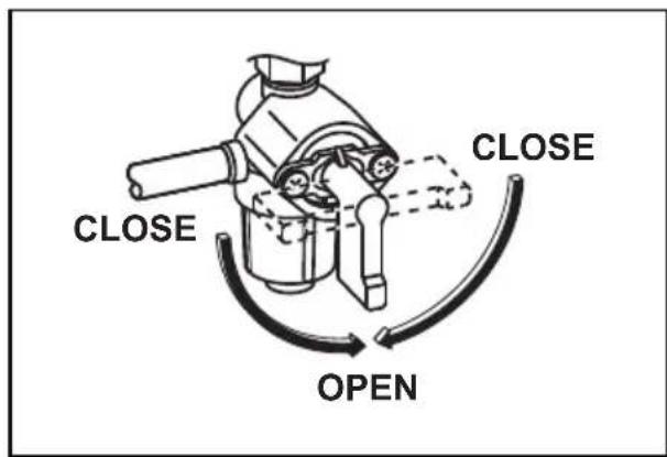
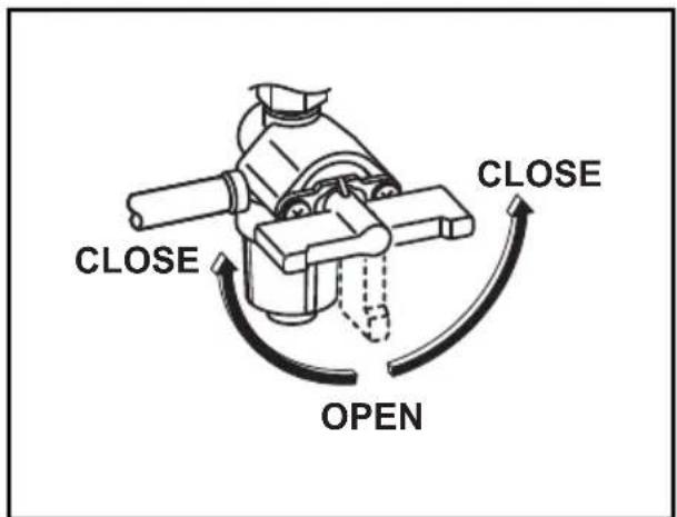
(2) Turn the fuel cock to the vertical (open) position
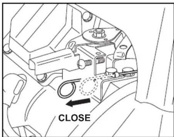
(3) (RGV13100T)
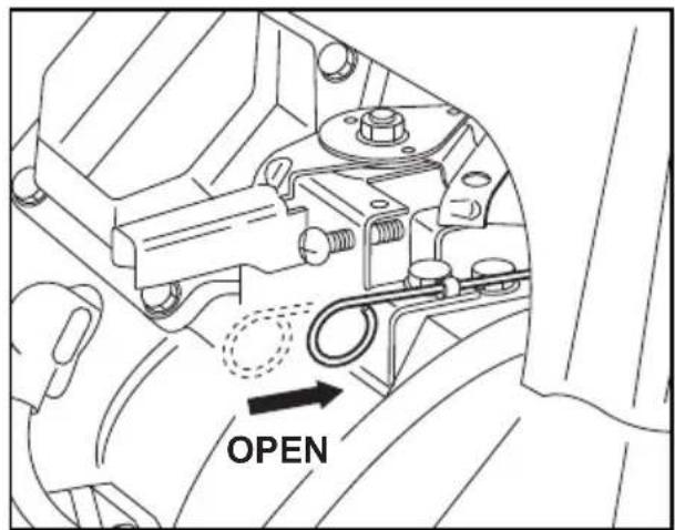
Pull the choke knob to the fully closed position.
NOTE :
Be sure to pull the choke even if the engine is warm.
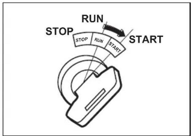
(4) Turn the starter switch to the "START" position. If the engine won't start, turn the switch back to "ON" position and then wait for approximately 10 seconds to try it again.
NOTE :
You might have to keep the starter running for at least 3 to 5 seconds, since the engine incorporates the mechanism in it where the ignition circuit is activated by the increase of hydraulic pressure.
flowchart
graph TD
    A["Start"] --> B["RUN"]
    B --> C["STOP"]
    C --> D["START"]
    style A fill:#f9f,stroke:#333
    style B fill:#ccf,stroke:#333
    style C fill:#cfc,stroke:#333
    style D fill:#fcc,stroke:#333
In the following occasion, two or three trials may be required for starting the engine :
(1) The very first starting of a new generator.
(2) After the refueling of the engine which has been stopped due to fuel shortage.
(3) Starting after the oil fi Iter change.
(RGV13100T)
Even if the engine has already been warmed, be sure to pull the choke knob.
(4) (RGV13100T)
Return the starter switch to "ON" position soon after the engine has started and then push the choke knob. In cold weather, be sure to push it gradually.
(5) Warm the engine up for a minute or two. Longer time would be needed in cold weather.
USING ELECTRIC POWER

WARNING
Make sure that the appliance is switched OFF before connecting it to the generator.
Do not move the generator while it is running.
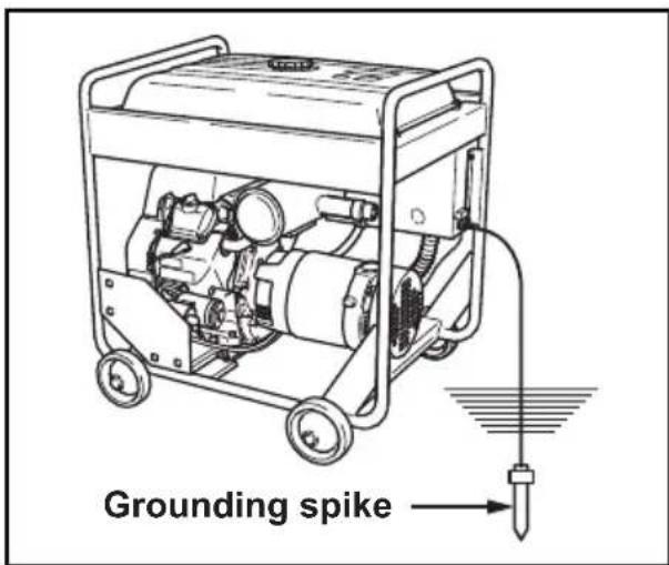
Be sure to ground the generator if the connected appliance is grounded. Failure to ground unit may lead to electrical shock.
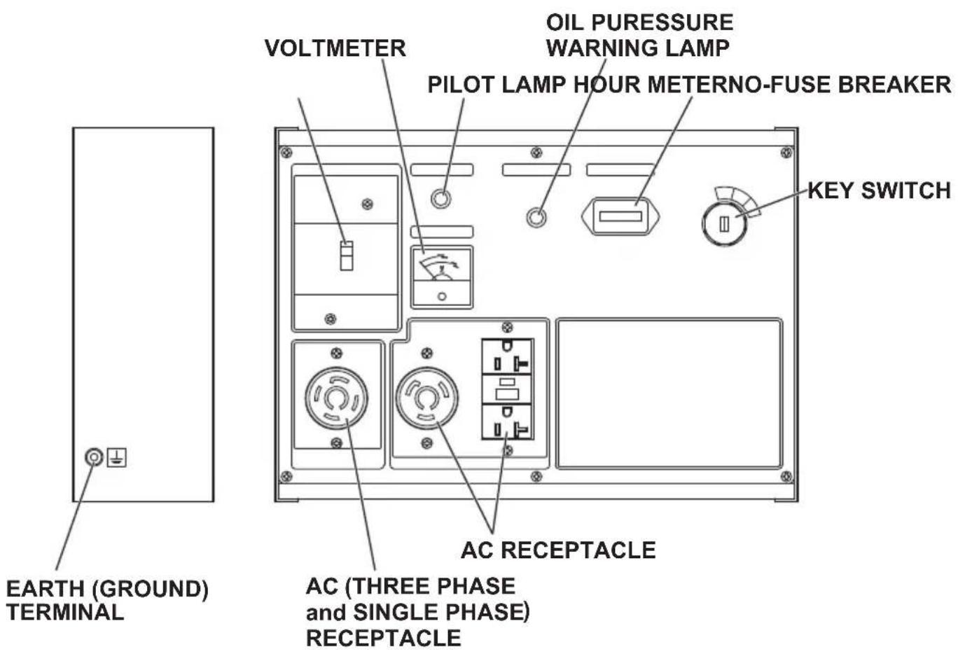
CONTROL PANEL
(RGV12100)
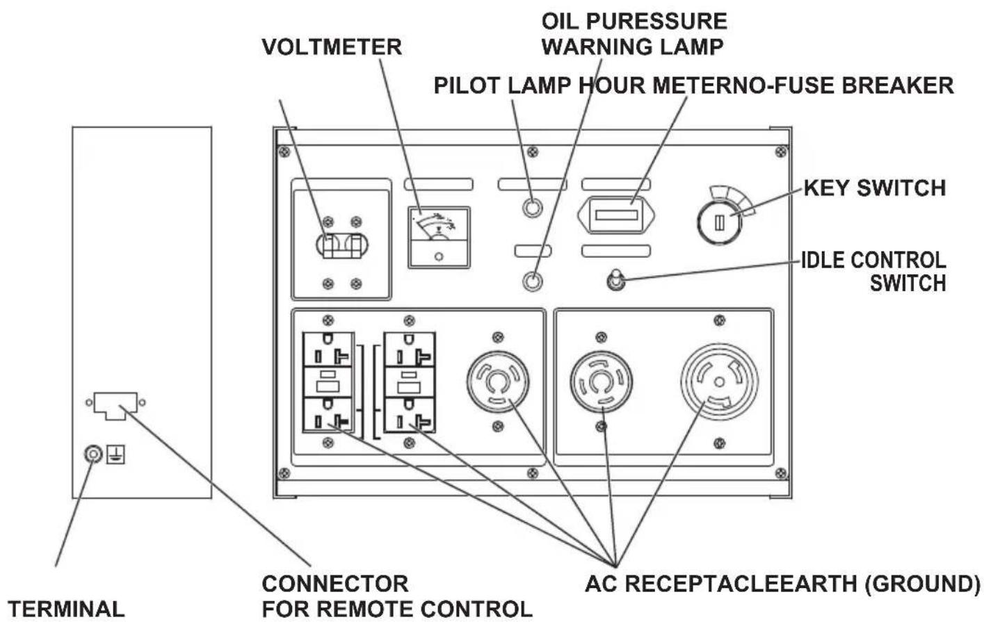
(RGV13100T)
(1) AC APPLICATION
(a) Ground the generator, using the ground terminal located at the side of the panel.
(b) Before starting the engine, check that the AC circuit breaker of the generator and the power switches of the appliances are turned off.
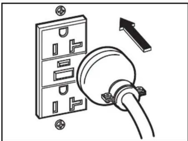
(c) Connect the plugs of the appliances to the receptacles before starting the engine. If you wish to use for a long period of time, connecting to the output terminal is recommended.
(d) Start the engine and check that the voltage meter is indicating correct voltage.
natural_image
Diagram of a wall-mounted electrical socket connected to a plug, with an arrow indicating upward force (no text or symbols present)Check the amperage of the receptacles used referring to TABLE 1, and be sure not to take a current exceeding the specified amperage.
Be sure that the total wattage of all appliances dose not exceed the rated output of the generator.
| Style Ampere | Receptacle AC plug Description | |||
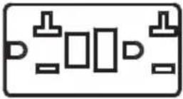 | up to 20A | NEMA5-20R | NEMA5-20P | GFCI (Ground Fault Circuit Interrupter)Receptacle,duplex(REC1) |
 | up to 30A | NEMAL5-30R | NEMAL5-30P | Locking Receptacle(REC2) |
 | up to 30A | NEMAL14-30R | NEMAL14-30P | Locking Receptacle(REC3) |
 | up to 50A | Locking Receptacle(REC4) | ||
 | up to 30A | NEMAL21-30R | NEMAL21-30P | Locking Receptacle(REC5) |
TABLE 1
WARNING
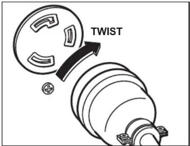
To take power out from the TWIST LOCK RECEPTACLE, insert the plug into the receptacle, and turn it clockwise to the lock position.
■Be sure to ground the generator if the connected electrical device is grounded.
NOTE :
When the AC circuit breaker turns off during operation, the generator is over loaded or the appliance is defective. Stop the generator immediately, check the appliance and / or generator for overloading or detect and have repaired as necessary by SUBARU Industrial Power Products dealer or service shop.
[CAUTION]
The duplex 120V receptacle is protected by a GFCI (Ground Fault Circuit Interrupter). GFCI shuts off the output current from the duplex 120V receptacle when a ground fault occurs in the generator or the appliance. Please note that other receptacles are not protected by GFCI.
GFCI RECEPTACLE
After starting the engine, check the GFCI for proper functioning by the following test procedure.
Push blue TEST button, The red RESET button will pop out exposing the word TRIP. Power is now off at the outlets protected by the GFCI, indicating that the device is functioning properly.
- TRIP dose not appear when testing, do not use the generator. Call a qualified electrician.
To restore power, push RESET button.

WARNING
If the RESET button pops out during operation, stop the generator immediately and call a qualified electrician for checking generator and the appliances.
AC (THREE PHASE) RECEPTACLE (RGV13100T only)
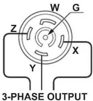
RGV13100T has a receptacle for three phase (208V) and single phase (120V) as follows :
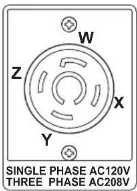
Three phase application (208V)
Insert the plug into the receptacle X, Y and Z.
Generator rated output : 10000VA
Single phase lower application (120V)
Insert the plug into the receptacle W and X, W and Y, W and Z.
Maximum one-third (1/3) of generator output can be utilized from each phase.
Generator rated output :
3324VA (120V x 27.7A)
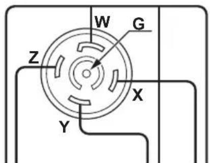
SINGLE-PHASE OUTPUT
NOTE :
When the AC circuit breaker turns off during operation, the generator is over loaded or the appliance is defective. Stop the generator immediately, check the appliance and / or generator for overloading or detect and have repaired as necessary by SUBARU Industrial Power Products dealer or service shop.
(e) Turn the breaker on to see if the pilot lamp lights up.
(f) Turn on the switch of the appliance.
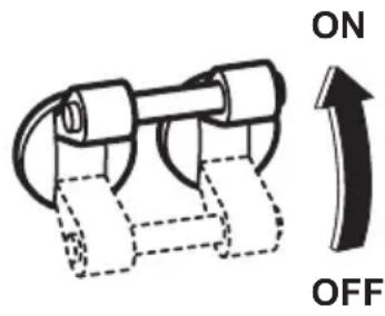

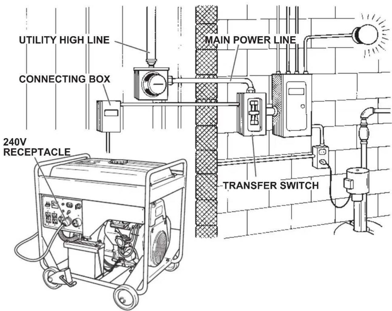
(2) CONNECTING TO DOMESTIC CIRCUIT (HOUSE WIRING for RGV12100)

WARNING
This generator is neutral grounded type (RGV12100). (ungrounded type RGV13100T)
If a generator is to be connected to residential or commercial power lines, such as a stand-by power source during power outage, all connections must be made by a licensed electrician.
Failure in connection may result in death, personal injury, damage to generator, damage to appliances, damage to the building's wiring or fire.
(a) When connecting a SUBARU generator to a house wiring, generator output power must be taken from the 240V-4P receptacle.
(b) Install a transfer switch.
A transfer switch must be installed to transfer the load from the commercial power source to the generator. This switch is necessary to prevent accidents caused by the recovery from power outage. Use a transfer switch of the correct capacity. Install transfer switch between the meter and the fuse or AC breaker box.
[CAUTION]
If the neutral wire of house wiring is grounded, be sure to ground the ground terminal of the generator. Otherwise an electric shock may occur to the operator.
![SUBARU RGV13100T - [CAUTION] - 2](/content/2026/05/998228/images/a704566802224d5a072eb6398b9e863724ac0289357708f5f9459e42d58001a5.jpg)
flowchart
graph TD
    A["Meter box"] --> B["Utility high line"]
    B --> C["X W Y"]
    C --> D["Transfer switch"]
    D --> E["House circuit breaker"]
    E --> F["120V appliance"]
    E --> G["120V appliance"]
    F --> H["240V appliance"]
    G --> H
    I["Generator"] --> J["(W)"]
    I --> K["(X)"]
    I --> L["(Y)"]
    M["OR"] --> N["(G)"]
    O["240V 4P- Receptacle"] --> P["(X)"]
    Q["240V 4P- Receptacle"] --> R["(Y)"]
    S["Generator"] --> T["(W)"]
    S --> U["(X)"]
    S --> V["(Y)"]
    style A fill:#f9f,stroke:#333
    style H fill:#ccf,stroke:#333
    style I fill:#cfc,stroke:#333
    style Q fill:#fcc,stroke:#333
(c) Operating the generator.
Turn the house AC breaker off before starting the generator.
Start the generator and warm it up.
Turn the house AC breaker on.
[CAUTION]
Do not start the generator with electrical appliance (s) connected and with their switches on.
Otherwise the appliance (s) may be damaged by the surge voltage at starting.
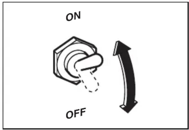
(3) IDLE CONTROL SWITCH (RGV12100 only)
IDLE CONTROL SWITCH automatically reduces engine speed when load is OFF, and automatically increases engine speed to rated r.p.m. when load is ON.
IDLE CONTROL SWITCH provides fuel economy and low noise operation at no-load running.
(1) HOW TO USE IDLE CONTROL SWITCH
Start the engine with IDLE CONTROL SWITCH off.
NOTE :
Warm up the engine without a load for a few minutes.
Turn IDLE CONTROL SWITCH on.
(2) CHECKING THE OPERATION
When IDLE CONTROL SWITCH does not operate normally, please check following :
Overloaded?
Please make it sure that the generator is not overload.
NOTE :
Most induction loads such as electric motors require three to five times more wattage than their ratings during starting.
This starting wattage should not exceed the rated output of the generator for proper operation of IDLE CONTROL SWITCH.
Turn IDLE CONTROL SWITCH off when the IDLE CONTROL SWITCH does not work normally under the rated output.
NOTE :
The IDLE CONTROL SWITCH may not operate when the applied load is under 40W. In such cases turn the IDLE CONTROL SWITCH off.
STOPPING THE GENERATOR
(1) Turn off the power switch of the electric equipment.
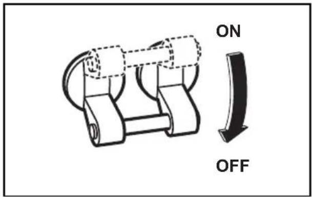
(2) Turn the AC circuit breaker to off.
(3) Unplug the cord from receptacle of the generator.
(4) Allow the engine to run at no-load for about 3 minutes to cool down before stopping.
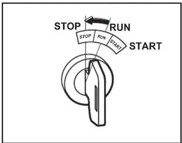
(5) Turn the starter switch to the STOP position.
(6)Close the fuel valve.
flowchart
graph TD
    A["Start"] --> B["RUN"]
    B --> C["STOP"]
    C --> D["STOP"]
    style A fill:#f9f,stroke:#333
    style B fill:#ccf,stroke:#333
    style C fill:#cfc,stroke:#333
    style D fill:#fcc,stroke:#333
(Except RGV13100T)
Some appliances need a "surge" of energy when starting.
This means that the amount of electrical power needed to start the appliance may exceed the amount needed to maintain its use.
Electrical appliances and tools normally come with a label indicating voltage, cycles/Hz, amperage (amps) and electrical power needed to run the appliance or tool.
Check with your nearest dealer or service center with questions regarding power surge of certain appliances or power tools.
■Electrical loads such as incandescent lamps and hot plates require the same wattage to start as is needed to maintain use.
- Loads such as fluorescent lamps require 1.2 to 2 times the indicated wattage during start-up.
- Loads for mercury lamps require 2 to 3 times the indicated wattage during start-up.
- Electrical motors require a large starting current. Power requirements depend on the type of motor and its use. Once enough “surge” is attained to start the motor, the appliance will require only 50% to 30% of the wattage to continue running.
■Most electrical tools require 1.2 to 3 times their wattage for running under load during use. (For example, a 9,000 watt generator can power a 3,200 to 7,000 watt electrical tool.)
- Loads such as submersible pumps, air conditioners and air compressors require a very large force to start. They need 3 to 5 times the normal running wattage in order to start. (For example, a 5,000 watt generator would only be able to drive a 1,800 to 3,100 watt pump.)
If the power consumption of electrical appliances exceeds the operating range or if there is short circuit or other problems in the appliances, the AC breaker could trip “OFF” or the rotation of the generator could be abnormally reduced. In this case, stop the generator to see if the power consumption of the appliances is too large and if there is a problem in the appliances.
■The frequency (the number of the generators rotation) was adjusted before the time of shipment. Changing the frequency could result in the generators breakdown, so refrain from changing it.
To determine the total wattage required to run a particular electrical appliance or tool, multiply the voltage figure of the appliance/tool by the amperage (amps) figure of same. The voltage and amperage (amps) information can be found on a name plate which is normally attached to electrical appliances and tools.
| Applications | Applicable Wattage(W) |
| RGV12100 | |
| 60 Hz | |
| Incandescent lamp, Heater 9,500 | |
| Fluorescent lamp, Electric tool 4,700 | |
| Pump, Compressor 2,400 |
NOTE:
The above wattage chart is general guide only. Refer to your specific appliance for correct wattage.
When you use two or more alternating current outlets at a time, be careful that the sum of the appliances' power consumption does not exceed the value specified in the above chart.
(All models)
VOLTAGE DROP IN ELECTRIC EXTENSION CORDS
When a long electric extension cord is used to connect an appliance or tool to the generator, a certain amount of voltage drop or loss occurs in the extension cord which reduces the effective voltage available for the appliance or tool.
The chart below has been prepared to illustrate the approximate voltage loss when an extension cord of 300 feet (approx. 100 meters) is used to connect an appliance or tool to the generator.
| Nominal cross section | A.W.G. | Allowable current | No.of strands / strands dia. | Resistance | Current Amp. | |||||||
| mm^2 | No. A | No./mm | Ω/100m | 1A 3A | 5A 8A | 10A | 12A | 15A | Voltage drop | |||
| 0.75 | 18 | 7 | 30/0.18 | 2.477 | 2.5V | 8V | 12.5V | — | — | — | — | |
| 1.27 | 16 | 12 | 50/0.16 | 1.486 | 1.5V | 5V | 7.5V | 12V | 15V | 18V | — | |
| 2.0 | 14 | 17 | 37/0.26 | 0.952 | 1V | 3V | 5V | 8V | 10V | 12V | 15V | |
| 3.5 | 12 to 10 | 23 | 45/0.32 | 0.517 | — | 1.5V | 2.5V | 4V | 5V | 6.5V | 7.5V | |
| 5.5 | 10 to 8 | 35 | 70/0.32 | 0.332 | — | 1V 2 | V 2. | 5V 3. | 5V 4 | V 5V | ||
7. SPARK ARRESTER
In a dry or wooded area, it is recommendable to use the product with a spark arrester. Some areas require the use of a spark arrester. Please check your local laws and regulations before operating your product.
The spark arrester must be cleaned regularly to keep it functioning as designed.
A clogged spark arrester :
●Prevents the flow of exhaust gas
- Reduces engine output
- Increases fuel consumption
●Makes starting difficult
[CAUTION]
If the engine has been running, the muffler and the spark arrester will be very hot. Allow the muffler to cool before cleaning the spark arrester.
How to remove the spark arrester
- Remove the flange bolts from the muffler cover and remove the muffler cover.
- Remove the special screw from the spark arrester and remove the spark arrester from the muffler.
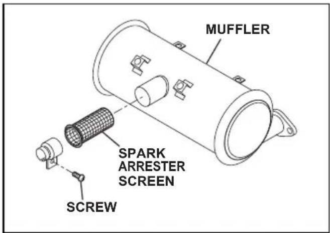
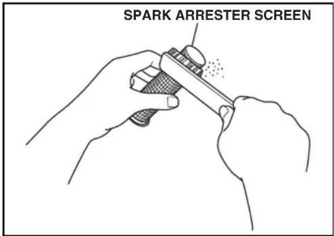
Clean the spark arrester screen
Use a brush to remove carbon deposits from the spark arrester screen. Be careful to avoid damaging the screen.
The spark arrester must be free of breaks and holes. Replace the spark arrester if it is damaged.
Install the spark arrester, and muffler protector in the reverse order of disassembly.
8. MAINTENANCE SCHEDULE
MAINTENANCE, REPLACEMENT, OR REPAIR OF THE EMISSION CONTROL DEVICES AND SYSTEMS MAY BE PERFORMED BY ANY NONROAD ENGINE REPAIR ESTABLISHMENT OR INDIVIDUAL.
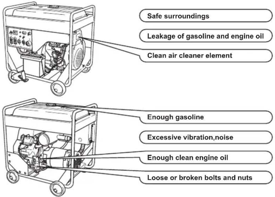
DAILY INSPECTION
Before running the generator, check the following service items:
PERIODIC MAINTENANCE
Periodic maintenance is vital to safe and efficient operation of your generator. Check the table below for periodic maintenance intervals.
IT IS ALSO NECESSARY FOR THE USER OF THIS GENERATOR TO CONDUCT THE MAINTENANCE AND ADJUSTMENTS ON THE EMISSION-RELATED PARTS LISTED BELOW TO KEEP THE EMISSION CONTROL SYSTEM EFFECTIVE.
The emission control system consists of the following parts :
(1) Carburetor and internal parts
(2) Cold start enrichment system, if applicable
(3) Intake manifold, if applicable
(4) Air cleaner elements
(5) Spark plug
(6) Magneto or electronic ignition system
(7) Spark advance/retard system, if applicable
(8) Exhaust manifold, if applicable
(9) Hoses, belts, connectors, and assemblies
The maintenance schedule indicated in the table is based on the normal generator operation. Should the generator be operated in extremely dusty condition or in heavier loading condition, the maintenance intervals must be shortened depending on the contamination of oil, clogging of filter elements, wear of parts, and so on.
Periodic Maintenance Schedule table
| Maintenance Items | Every 8 hours (Daily) | Every 50 hours (Weekly) | Every 200 hours (Monthly) | Every 500 hours | Every 1000 hours |
| Clean generator and check bolt and nuts | ● (Daily) | ||||
| Check for leakage from hoses and fi tting | ● (Daily) | ||||
| Check and refi ll engine oil | ● (Refi ll daily up to upper level) | ||||
| Change engine oil (*Note1) | ● (Initial 20 hours) | ● (Every 100 hours) | |||
| Replace engine oil fi lter (*Note1) | ● (Initial 20 hours) | ● | |||
| Check battery electrolyte fi uid level | ● | ||||
| Clean spark plug | ● | ||||
| Clean air cleaner | ● | ||||
| Clean spark arrester | ● (Every 100 hours) | ||||
| Replace air cleaner element | ● | ||||
| Clean fuel strainer | ● | ||||
| Clean and adjust spark plug and electrodes | ● | ||||
| Replace spark plug | ● | ||||
| Remove carbon from cylinder head (*Note 2) | ● | ||||
| Clean and adjust carburetor (*Note 2) | ● | ||||
| Clean engine base (oil pan) | ● | ||||
| Check and adjust valve clearance (*Note 2) | ● | ||||
| Clean and replace carbon brushes | ● | ||||
| Replace fuel lines | ● (Every 2 years) | ||||
| Overhaul engine (*Note 2) | ● |
*Note 1: Initial oil change should be performed after first twenty (20) hours of operation. Thereafter change oil every hundred (100) hours.
Before changing oil, check for a suitable way to dispose of old oil.
Do not pour it down into sewage drains, onto garden soil or into open streams. Your local zoning or environmental regulations will give you more detailed instructions on proper disposal.
*Note 2: As to the procedures for these items, please refer to the SERVICE MANUAL or consult your nearest service dealer.
*Note 3: More frequent oil changing, oil filter replacement and air cleaner service on replacement may be necessary depending on operating conditions.
This would include dusty environment, high ambient temperature, heavy engine loading.
9. "HOW-TO" MAINTENANCE
ENGINE OIL CHANGE
■Initial oil change
• • • • • After 20 hours of operation
■Thereafter
• • • • • Every 100 hours of operation
- When changing oil, stop the engine and loosen the drain plug.
- Re-install the drain plug before refilling oil.
- Refer to the recommended oil table on page 6.
- Always use the best grade and clean oil. Contaminated oil, poor quality oil and shortage of oil cause damage to engine or shorten the engine life.
Oil capacity (Upper level) : L(U.S. gal)
RGV12100 1.55 (0.41)
RGV13100T 1.55 (0.41)
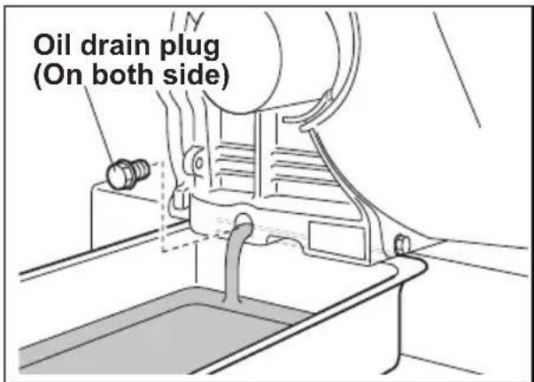
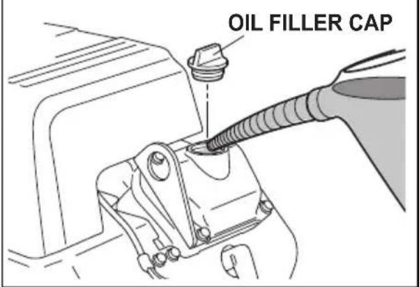
ENGINE OIL FILTER REPLACEMENT
Initial engine oil filter replacement should be performed after 20 hours of operation. Thereafter replace the engine oil filter every 200 hours.
When installing a new oil filter, apply oil to O-ring, attach the oil filter in position and tighten 2/3 turns by hand or with wrench after touching the O-ring to the sealing surface of engine.
Run the engine for a minute ; stop the engine and check for oil leakage around the oil filter and recheck the oil level.
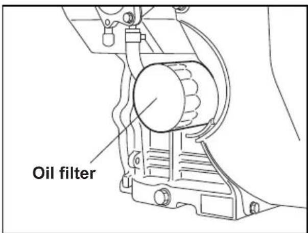
[CAUTION]
To prevent injury, pay attention to the spilled hot engine oil when replacing engine oil filter.
SERVICING AIR CLEANER
A dirty air cleaner element will cause starting difficulty, power loss, engine malfunctions, and shorten engine life extremely.
Always keep the air cleaner element clean. Replaced the air cleaner element set more often in dusty environments.
The air cleaner paper inner element and urethane foam outer element can be removed after removing knob and air cleaner cover. When installing, set the paper element and urethane foam on the air cleaner base. Check that the grommet is in position, and then install the cover with knob tightened securely.
Urethane Foam cleaning
Wash and clean the urethane foam in kerosene. Saturate in a mixture
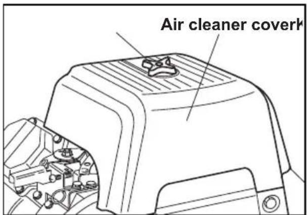
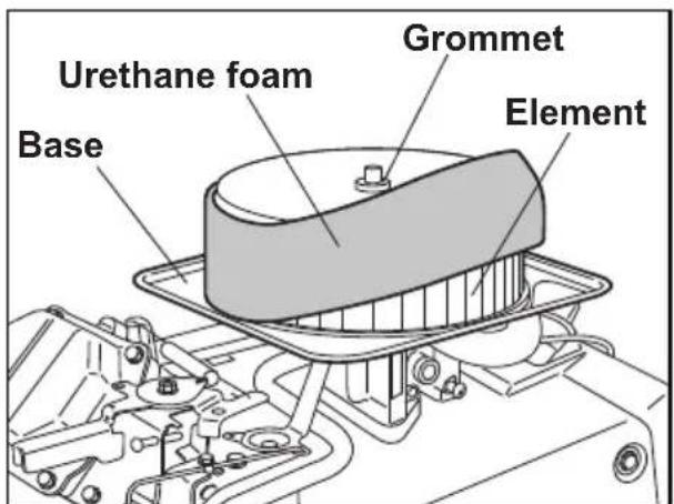
of 3 parts kerosene and 1 part engine oil, and then squeeze to remove excess oil. Clean or replace the urethane foam element every 50 hours. (more often in dusty environments)
Paper element
Clean by tapping gently to remove dirt and blow off dust. Never use oil.
Clean or replace the paper element every 50 hours of operation, and replace element set every 200 hours.
CLEANING AND ADJUSTING SPARK PLUG
(a) Unplug the high-voltage cables (located at the outlet panel and lead-acid battery).
(b) Using the supplied plug wrench and handle, turn it counterclockwise until it comes off.
(c) Clean the area around the mounting hole.
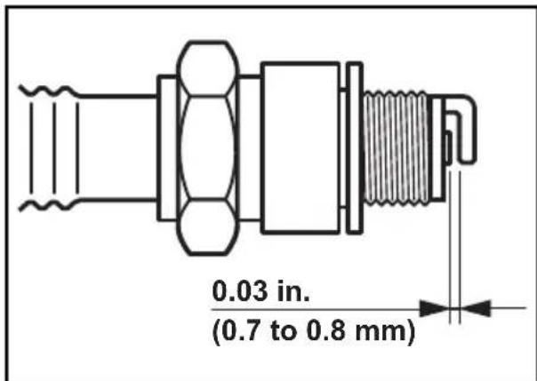
(d) Clean the electrodes if they are dirty. Adjust the clearance to 0.03 in. (0.7-0.8 mm). Replace it with a new one if the abrasion has developed to the degree where a flat surface cannot be obtained on its projection. If the electrodes turn black, also inspect the air cleaner.
(e) Attach and tighten the plug with the specified torque: 25 to 30 Nm (2.5 to 3.0 kg-m).
(f) After checking that the contact area inside the plug cap is not corroded, connect the high-voltage cables.
CLEANING FUEL STRAINER
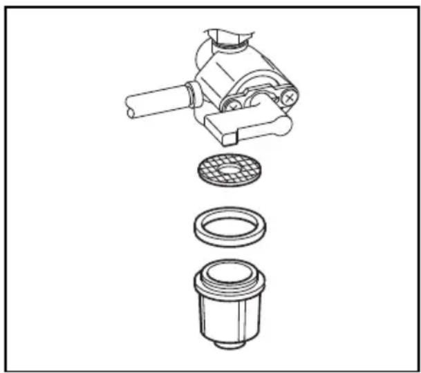
Dirt and water in the fuel are removed by the fuel strainer.
(a) Remove the strainer cup and throw away water and dirt.
(b) Clean the screen and strainer cup with gasoline.
(c) Tightly fasten the cup to main body, making sure to avoid fuel leak.
Spark plug : NGK BPR5ES (CHAMPION RN11YC)
natural_image
Exploded view diagram of a mechanical assembly showing internal components (no text or labels)FUEL HOSE REPLACEMENT

WARNING
Take extreme caution when replacing fuel hose ; gasoline is flammable.
Replace the fuel hose every 1,000 hours or every 2 years.
If fuel hose leak is found, replace the fuel hose immediately.
CHECKING CARBON BRUSH
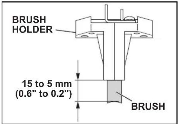
If the brush become excessively worn, its contact pressure with the slip ring changes and causes a roughened surface on the slip ring, resulting in irregular generator performance.
Check the brush every 500 hours or if generator performance is irregular.
If the brush is 0.2 in.(5 mm) long or less, replace it with a new one.
(a) (RGV12100)
Remove the brush cover.
(RGV13100T)
Remove the end cover and brush cover.
(b) Disconnect the wire connector and remove the brush.
(c) Carefully note the brush direction and relative position with the slip ring when installing new brush.
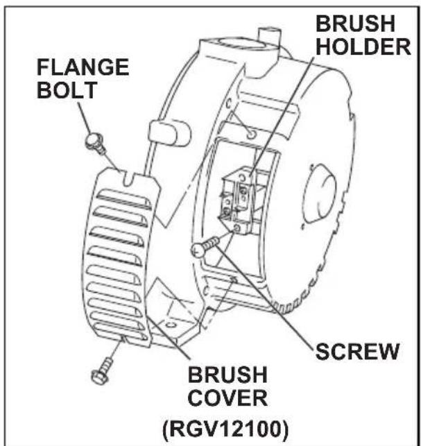
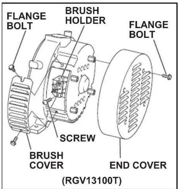
Please have an authorized SUBARU Industrial Power Products service dealer modify this engine if it is to be run continuously above 5,000 feet (1,500 meters). Failure to do so, may result in poor engine performance, spark plug fouling, hard starting, and increased emissions.
Carburetor modification by an authorized SUBARU Industrial Power Products service dealer will improve performance and allow that this engine meets EPA (Environmental Protection Agency) and California ARB (Air Resources Board) emission standards throughout its useful life.
An engine converted for high altitudes can not be run at 5,000 feet or lower. In doing so, the engine will overheat and cause serious engine damage. Please have an authorized SUBARU Industrial Power Products service dealer restore high altitude modified engines to the original factory specification before operating below 5,000 feet.
10. PREPARATION FOR STORAGE
The following procedures should be followed prior to storage of your generator for periods of 6 months or longer.
Drain fuel from fuel tank and strainer (cup) carefully by disconnecting the fuel line. Gasoline left in the fuel tank will eventually deteriorate making engine-starting difficult.
In order to remove the fuel in the carburetor, run the engine at no-load until it stops.
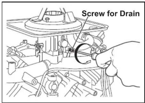
Disconnect the terminal of the battery.
Change engine oil.
Check for loose bolts and screws, tighten them if necessary.
●Clean generator thoroughly with oiled cloth. Spray with preservative if available. NEVER USE WATER TO CLEAN GENERATOR!
Store generator in a well ventilated, low humidity area.
11. TROUBLESHOOTING
When generator engine fails to start after several attempts, or if no electricity is available at the output receptacles, check the possible causes in accordance with the following table. If your generator still fails to start or generate electricity, contact your nearest SUBARU Industrial Power Products dealer or authorized service center for further information or corrective procedures.
| Possible causes | Low battery | Blown fuse | Deteriorated fuel | Fuel piping | Clogging of Air cleaner | Clogging of Cooling air intake | Low oil level | Faulty spark plug | Overload by connected appliance | Incorrect or poor connection of wires | Insufficient capacity of extension cable | Carbon brushes are excessively worn | ||
| Leakage | Clogging | |||||||||||||
| Starter won't run | × | × | ||||||||||||
| Starter runs, but Engine won't start. | × | × | × | × | × | × | × | |||||||
| During operation | Rotation decreased | × | × | × | × | × | × | × | × | |||||
| Unstable rotation | × | × | × | × | × | × | ||||||||
| Breaker turned off | × | × | ||||||||||||
| Low power | × | × | × | × | × | × | × | × | × | |||||
×
12. WIRING DIAGRAM
(RGV12100)
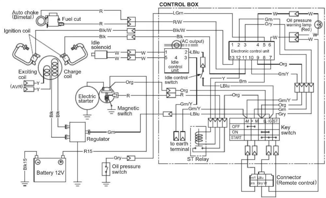
flowchart
graph TD
    A["Auto choke (Bimetal)"] --> B["Fuel cut"]
    B --> C["R"]
    C --> D["R/W"]
    D --> E["Blk/W"]
    E --> F["Blk"]
    F --> G["Blk"]
    G --> H["Idle solenoid"]
    H --> I["W"]
    I --> J["W"]
    J --> K["Charge coil"]
    K --> L["Y"]
    L --> M["Y"]
    M --> N["Blk15"]
    N --> O["Battery 12V"]
    P["Ignition coil"] --> Q["Exciting coil (AVR)"]
    Q --> R["Y"]
    R --> S["Y"]
    S --> T["Blk"]
    T --> U["Blink"]
    U --> V["Blk"]
    V --> W["Blk"]
    W --> X["Regulator"]
    X --> Y["R15"]
    Y --> Z["Gry"]
    Z --> AA["Oil pressure switch"]
    AB["Electric starter"] --> AC["Magnetic switch"]
    AD["Electronic control unit"] --> AE["LBlu"]
    AF["Regulator"] --> AG["Gm/Y"]
    AG --> AH["Gm/Y"]
    AH --> AI["LBlu"]
    AI --> AJ["St Relay"]
    AK["ST Relay"] --> AL["to earth terminal"]
    AL --> AM["Org"]
    AM --> AN["Gm/Y"]
    AN --> AO["Org"]
    AO --> AP["Gm/Y"]
    AP --> AQ["Gry"]
    AQ --> AR["Key switch"]
    AR --> AS["-M + M EL IG ST"]
    AR --> AT["OFF ON START"]
    AR --> AU["Gry W"]
    AV["Controller (Remote control)"] --> AW["Gm/Y LBlu"]
    AW --> AX["Gm LBlu"]
    AX --> AY["Gry W"]
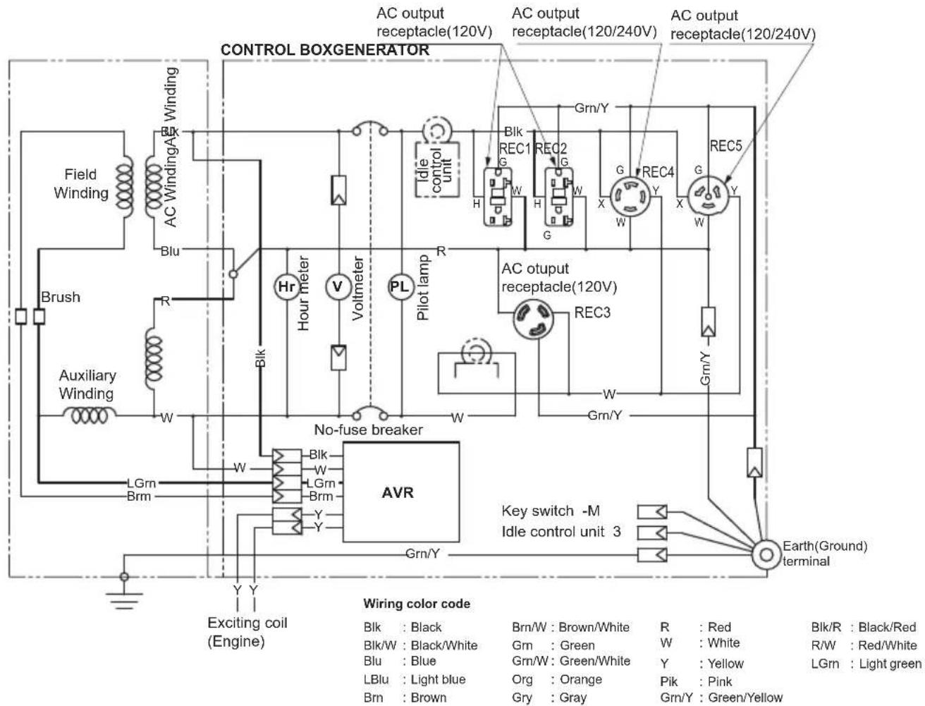
(RGV13100T)
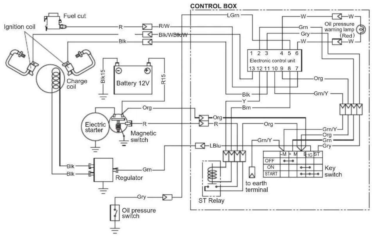
flowchart
graph TD
    A["Ignition coil"] --> B["Fuel cut"]
    B --> C["Charge coil"]
    C --> D["Battery 12V"]
    D --> E["Regulator"]
    E --> F["Oil pressure switch"]
    D --> G["Magnetic switch"]
    G --> H["Organ"]
    H --> I["ST Relay"]
    I --> J["Key switch"]
    J --> K["St. relay"]
    K --> L["ST 1G ST"]
    L --> M["Off"]
    L --> N["START"]
    M --> O["org"]
    N --> P["Gry"]
    O --> Q["Org/Y"]
    P --> R["Org/Y"]
    Q --> S["Org/Y"]
    R --> T["Grn/Y"]
    S --> U["Grn/Y"]
    T --> V["Grn/Y"]
    U --> W["Grn/Y"]
    V --> X["Grn/Y"]
    W --> Y["Grn/Y"]
    X --> Z["Grn/Y"]
    Y --> AA["Grn/Y"]
    Z --> AB["Grn/Y"]
    AA --> AC["Grn/Y"]
    AB --> AD["Grn/Y"]
    AC --> AE["Grn/Y"]
    AD --> AF["Grn/Y"]
    AE --> AG["Grn/Y"]
    AF --> AH["Grn/Y"]
    AG --> AI["Grn/Y"]
    AH --> AJ["Grn/Y"]
    AI --> AK["Grn/Y"]
    AJ --> AL["Grn/Y"]
    AK --> AM["Grn/Y"]
    AL --> AN["Grn/Y"]
    AM --> AO["Grn/Y"]
    AN --> AP["Grn/Y"]
    AO --> AQ["Grn/Y"]
    AP --> AR["Grn/Y"]
    AQ --> AS["Grn/Y"]
    AR --> AT["Grn/Y"]
    AS --> AU["Grn/Y"]
    AT --> AV["Grn/Y"]
    AU --> AW["Grn/Y"]
    AV --> AX["LBlu"]
    AW --> AY["LBlu"]
    AX --> AZ["LBlu"]
    AY --> BA["LBlu"]
    AZ --> BB["LBlu"]
    BA --> BC["LBlu"]
    BB --> BD["LBlu"]
    BC --> BE["LBlu"]
    BD --> BF["LBlu"]
    BE --> BG["LBlu"]
    BF --> BH["LBlu"]
    BG --> BI["LBlu"]
    BH --> BJ["LBlu"]
    BI --> BK["LBlu"]
    BJ --> BL["LBlu"]
    BK --> BM["LBlu"]
    BL --> BN["LBlu"]
    BM --> BO["LBlu"]
    BN --> BP["LBlu"]
    BO --> BQ["LBlu"]
    BP --> BR["LBlu"]
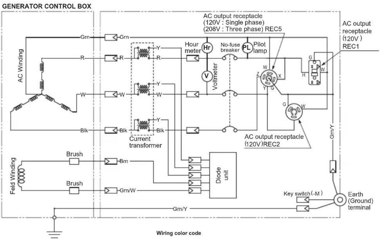
flowchart
graph TD
    subgraph GENERATOR_CONTROL_BOX
        A["AC Winding"] --> B["Gm"]
        C["AC Winding"] --> D["R"]
        E["AC Winding"] --> F["W"]
        G["AC Winding"] --> H["Bk"]
        I["Feld Winding"] --> J["Brush"]
        K["Feld Winding"] --> L["Brush"]
        M["Current transformer"] --> N["Diode unit"]
        O["AC output receptacle (120V) REC5"] --> P["Hr"]
        Q["AC output receptacle (120V) REC1"] --> R["H"]
        S["AC output receptacle (120V) REC2"] --> T["X"]
        U["AC output receptacle (120V) REC5"] --> V["Voltmeter"]
        W["AC output receptacle (120V) REC1"] --> X["G"]
        Y["AC output receptacle (120V) REC2"] --> Z["G"]
        AA["Key switch (-M)"] --> AB["Earth (Ground) terminal"]
    end
    subgraph Wiring_COLOR_CODE
        AC["AC Winding"] --> AD["Y"]
        AE["AC Winding"] --> AF["Y"]
        AG["AC Winding"] --> AH["Y"]
        AI["AC Winding"] --> AJ["Y"]
        AK["AC Winding"] --> AL["Y"]
        AM["AC Winding"] --> AN["Y"]
        AO["AC Winding"] --> AP["Y"]
        AQ["AC Winding"] --> AR["Y"]
        AS["AC Winding"] --> AT["Y"]
        AU["AC Winding"] --> AV["Y"]
        AW["AC Winding"] --> AX["Y"]
        AY["AC Winding"] --> AZ["Y"]
        BA["AC Winding"] --> BB["Y"]
        BC["AC Winding"] --> BD["Y"]
        BE["AC Winding"] --> BF["Y"]
        BG["AC Winding"] --> BH["Y"]
        BI["AC Winding"] --> BJ["Y"]
        BK["AC Winding"] --> BL["Y"]
        BM["AC Winding"] --> BN["Y"]
        BO["AC Winding"] --> BP["Y"]
        BQ["AC Winding"] --> BR["Y"]
        BS["AC Winding"] --> BT["Y"]
        BU["AC Winding"] --> BV["Y"]
        BW["AC Winding"] --> BX["Y"]
        BY["AC Winding"] --> BZ["Y"]
        CA["AC Winding"] --> CB["Y"]
        CC["AC Winding"] --> CD["Y"]
        DD["AC Winding"] --> DE["Y"]
        FD["AC Winding"] --> FD
    end
    style AC fill:#f9f,stroke:#333
    style AE fill:#f9f,stroke:#333
    style BC fill:#f9f,stroke:#333
    style BB fill:#f9f,stroke:#333
    style DC fill:#f9f,stroke:#333
    style AF fill:#f9f,stroke:#333
    style AG fill:#f9f,stroke:#333
    style BH fill:#f9f,stroke:#333
    style BI fill:#f9f,stroke:#333
    style BJ fill:#f9f,stroke:#333
    style AK fill:#f9f,stroke:#333
    style BB fill:#f9f,stroke:#333
    style AC fill:#ccf,stroke:#333
    style AD fill:#ccf,stroke:#333
    style AE fill:#ccf,stroke:#333
    style AF fill:#ccf,stroke:#333
    style AG fill:#ccf,stroke:#333
    style BH fill:#ccf,stroke:#333
    style BI fill:#ccf,stroke:#333
    style BJ fill:#ccf,stroke:#333
    style AK fill:#ccf,stroke:#333
    style BB fill:#ccf,stroke:#333
    style AC fill:#ccf,stroke:#333
    style AD fill:#ccf,stroke:#333
    style AE fill:#ccf,stroke:#333
    style AF fill:#ccf,stroke:#333
    style BG fill:#ccf,stroke:#333
    style BH fill:#ccf,stroke:#333
    style BI fill:#ccf,stroke:#333
    style BJ fill:#ccf,stroke:#333
    style AK fill:#ccf,stroke:#333
    style BB fill:#ccf,stroke:#333
    style AC fill:#ccf,stroke:#333
    style AD fill#FF,stroke:#FF0000
    style AE fill#FF,stroke:#FF0000
    style AF fill#FF,stroke:#FF0000
    style BG fill#FF,stroke:#FF0000
    style BH fill#FF,stroke:#FF0000
    style BI fill#FF,stroke:#FF0000
    style BJ fill#FF,stroke:#FF0000
    style AK fill#FF,stroke:#FF0000
    style BB fill#FF,stroke:#FF0000
    style AC fill#FF,stroke:#FF0000
    style AD fill#FF,stroke:#FF0000
    style AE fill#FF,stroke:#FF0000
    style AF fill#FF,stroke:#FF0000
    style BG fill#FF,stroke:#FF0000
    style BH fill#FF,stroke:#FF0000
    style BI fill#FF,stroke:#FF0000
    style BJ fill#FF,stroke:BBB
    style AK fill#FF,stroke:#FF0000
    style BB fill#FF,stroke:#FF0000
    style AC fill#FF,stroke:#FF0000
    style AD fill#FF,stroke:#FF0000
    style AE fill#FF,stroke:#FF0000
    style AF fill#FF,stroke:#FF0000
    style BG fill#FF,stroke:BBB
    style BH fill#FF,stroke:#FF0000
    style BI fill#FF,stroke:BBB
Wiring color code
| Blk : Black | Bm/W : Brown/White | R : Red | Blk/R : Black/Red |
| Blk/W : Black/White | Grn : Green | W : White | R/W : Red/White |
| Blu : Blue | Grn/W : Green/White | Y : Yellow | LGrn : Light green |
| LBlu : Light blue | Org : Orange | Pik : Pink | |
| Bm : Brown | Gry : Gray | Gm/Y : Green/Yellow |
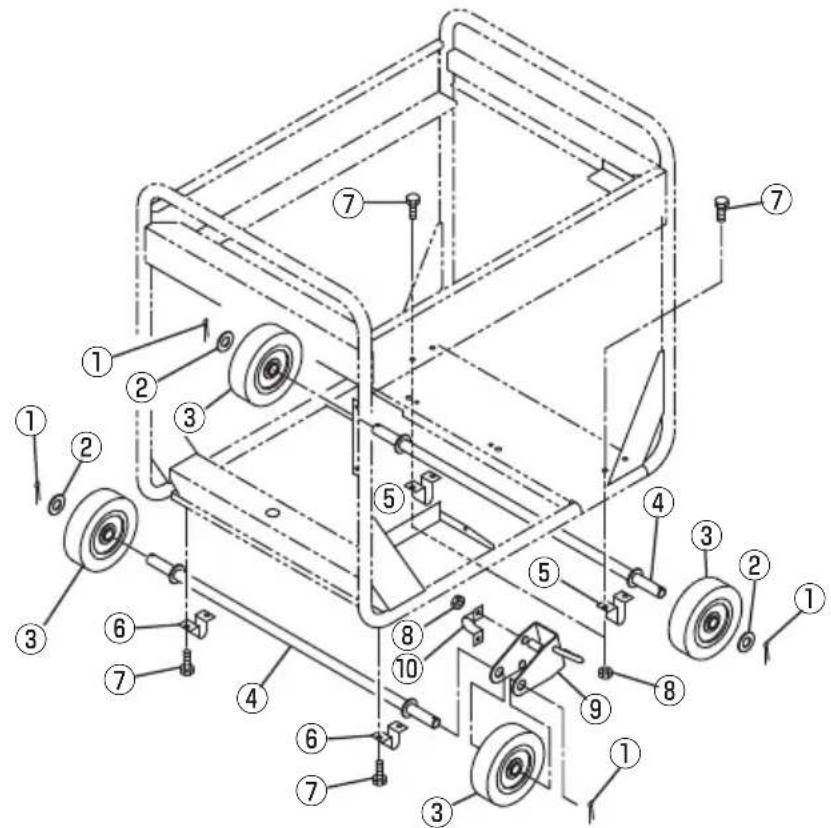
"HOW-TO" INSTALL THE WHEEL
(1) Checking of supplied accessories
(2)Tool preparation
■Hoist or square bar (100mm by 100mm, length : 700mm)
Plier
Spanner or socket wrench (12mm), 2 units
(3)Installation procedures
(a) Raise the generator by about 100 ~mm , with hoist or with square bar put under the bottom panel.
(b) Attach wheel mounting parts ①, ②, stopper ⑨, using clamp ⑩, ⑧ and wheel ③, to wheel shaft ④.
Then check that wheel ③ is rotated smoothly. If moving turns out to be too complicated, assemble them together using grease. (4 locations / 2 pieces)
(c) Bend the tip of ①according to the shape of wheel shaft ④ as possible.
(d) Attach the assembled shaft to the foundation plate of the engine, using ⑤, ⑦, and ⑧.
(e) Attach the other shaft to the foundation plate of the generating unit, using ⑥ and ⑦. (⑧ is not used.)
The tightening torque of bolts should be 20 to 25 Nm (2.0 to 2.5 kg-m).
ISSUE EMD-GU7306

SUBARU
FUJI HEAVY INDUSTRIES LTD. INDUSTRIAL PRODUCTS COMPANY
4-410 ASAHI, KITAMOTO-SHI, SAITAMA, 364-8511, JAPAN
TEL: +81-48-593-7798 FAX: +81-48-593-7946
http://www.subaru-robin.jp
PRINTED IN JAPAN January 2012
- DANGER
- WARNING:
- (California only)
- AIR INDEX
- FOREWORD
- CONTENTS
- Symbols and Meanings
- SAFETY PRECAUTIONS
- WARNING
- CAUTION
- CAUTION : PRECAUTIONS ON THE HANDLING OF THE WARNING LABEL
- Warning Label Exclusively for the United States and Canada
- Check that following accessories come with your SUBARU Generator.
- Be sure to replenish with engine oil.
- (See page 6 for details.)
- Notes on installation
- SPECIFICATIONS
- NOTE
- COMPONENTS
- PRE-OPERATION CHECKS
- CHECK ENGINE OIL
- NOTE:
- Recommended engine oil:
- CHECK ENGINE FUEL.
- NOTE : THIS ENGINE IS CERTIFIED TO OPERATE ON AUTOMOTIVE UNLEADED GASOLINE.
- NOTE :
- Fuel Amount
- BATTERY INSTALLATION
- Recommended Battery
- [CAUTION]
- CHECK COMPONENT PARTS
- CHECK GENERATOR SURROUNDINGS
- OPERATING PROCEDURES
- STARTING THE GENERATOR
- (RGV13100T)
- (RGV13100T)
- USING ELECTRIC POWER
- CONTROL PANEL
- (RGV12100)
- AC APPLICATION
- GFCI RECEPTACLE
- AC (THREE PHASE) RECEPTACLE (RGV13100T only)
- IDLE CONTROL SWITCH (RGV12100 only)
- STOPPING THE GENERATOR
- (Except RGV13100T)
- (All models)
- VOLTAGE DROP IN ELECTRIC EXTENSION CORDS
- SPARK ARRESTER
- How to remove the spark arrester
- Clean the spark arrester screen
- MAINTENANCE SCHEDULE
- DAILY INSPECTION
- PERIODIC MAINTENANCE
- "HOW-TO" MAINTENANCE
- ENGINE OIL CHANGE
- ENGINE OIL FILTER REPLACEMENT
- SERVICING AIR CLEANER
- CLEANING AND ADJUSTING SPARK PLUG
- CLEANING FUEL STRAINER
- FUEL HOSE REPLACEMENT
- CHECKING CARBON BRUSH
- PREPARATION FOR STORAGE
- TROUBLESHOOTING
- WIRING DIAGRAM
- "HOW-TO" INSTALL THE WHEEL
Brand : SUBARU
Model : RGV13100T
Category : Generator