
CM1001D - Subwoofer SoundTube - Free user manual and instructions
Find the device manual for free CM1001D SoundTube in PDF.


| Type | Subwoofer |
| Brand | SoundTube |
| Model | CM1001D |
| Dimensions (H x W x D) | 14.0 x 12.5 x 12.5 in (35.6 x 31.8 x 31.8 cm) |
| Weight | 22 lb (10 kg) |
| Power Handling (RMS) | 150 W |
| Peak Power Handling | 300 W |
| Frequency Response | 30 Hz - 150 Hz |
| Impedance | 8 ohms |
| Driver Size | 10 in (25.4 cm) |
| Enclosure Type | Ported |
| Inputs | Speaker level, Line level (RCA) |
| Finish | Black textured |
| Mounting Options | Floor standing |
| Safety | Do not expose to moisture; ensure adequate ventilation around amplifier |
| Cleaning | Wipe with a dry, soft cloth |
| Replaceable Parts | Fuse (located near power input) |
| Repairability | Serviceable by authorized technician; driver and amplifier module replaceable |
| Intended Use | Home theater, commercial audio |
| Warranty | Limited 2-year warranty |
Frequently Asked Questions - CM1001D SoundTube
User questions about CM1001D SoundTube
0 question about this device. Answer the ones you know or ask your own.
Ask a new question about this device
Download the instructions for your Subwoofer in PDF format for free! Find your manual CM1001D - SoundTube and take your electronic device back in hand. On this page are published all the documents necessary for the use of your device. CM1001D by SoundTube.
USER MANUAL CM1001D SoundTube
Install Instructions For:
CM800d, CM890d and CM1001d speakers

© 2008 SoundTube Entertainment, Inc. All rights reserved. PN INS-CMd Rev09.15.08
CM800d, CM890d, and CM1001d - UL listed 1480 & 2043
Warning
SoundTube speakers must be installed by a professional audio installer/contractor. For safety and for optimum audio performance, installer must follow all directions issued by SoundTube Entertainment.

Warning
Do not spec or install speaker near support beam, ventilation duct or other structure that may interfere with speaker function or dispersion.

- Unpack speaker and set aside grille assembly.

- Keep Styrofoam installation aid/paint mask attached to speaker until speaker installation is complete.

- Use included tile bridge to mark cutout in tile.

- Use Rotozip or other tool to cut hole. Hole diameter 325.1 mm (12.80 in)

- Insert speaker into mounting hole on ground with installation aid in place. Tighten both bolts located on the baffle face to actuate the mounting wings. Firmly secure both sides – do not over-tighten. Replace assembled tile and speaker into tile grid.
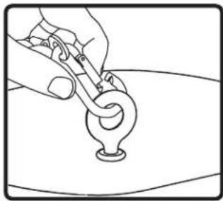
- For added support attach eyelet end of suspension cable to the rear of speaker using the carabiner. Attach the other end of support cable to secure structure using speedclamp. If required, attach the seismic restraint system to the sheet-metal tab on the side of speaker (seismic restraint not included).

- Thread signal wire through conduit cover plate. Connect signal wire to 4-pin Euroblock plug. Tighten unused terminal screws. Use inside positive and negative inputs for either voice coil or distributed systems. For daisy chaining, use outside positive and negative terminals. Euroblock must be plugged in for daisy chain to function.

- Insert the Euroblock plug into the Euroblock jack on the side panel of the speaker and replace the conduit cover plate. For UL-compliant installations, a strain relief (not supplied) may be inserted into the hole in the conduit cover plate.
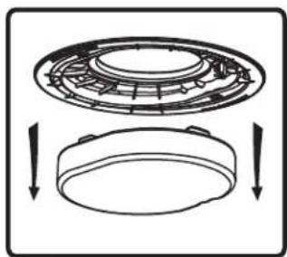
- If you are not painting the ceiling, remove and discard the paint mask.

- Select the tap position by adjusting the rotary switch to the desired high impedance value or voice coil bypass mode. The switch is preset to the maximum tap setting in 70.7 V mode.
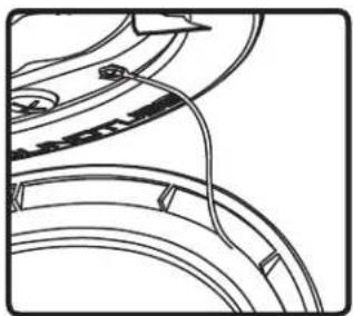
- Attach the grille and bezel seismic restraint to the baffle with the provided screw.

- Attach the grille – position the grille over the baffle and allow the magnets to attract the grille into place. Be sure the grille is properly centered over the baffle.

- Unpack the speaker and set aside the grille assembly.

- Keep the Styrofoam installation aid/paint mask attached to the speaker until speaker installation is complete.
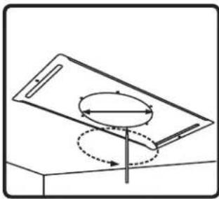
- Use the included tile bridge to mark the cutout in the sheetrock.
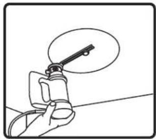
- Use a Rotozip or other tool to cut the hole. Hole diameter: 325.1 mm (12.80 in).

- Thread the signal wire through the conduit cover plate. Connect the signal wire to the 4-pin Euroblock plug. Tighten unused terminal screws. Use the inside positive and negative inputs for either voice coil or distributed systems. For daisy chaining, use the outside positive and negative terminals. The Euroblock must be plugged in for daisy chain to function.

- Insert the Euroblock plug into the Euroblock jack on the side panel of the speaker and replace the conduit cover plate. For UL-compliant installations, a strain relief (not supplied) may be inserted into the hole in the conduit cover plate.
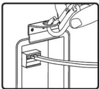
- If seismic restraint is required, attach the suspension cable to the sheet-metal tab on the side of the speaker.

- Insert the speaker into the mounting hole with the installation aid in place. Tighten both bolts located on the baffle face to actuate the mounting wings. Firmly secure both sides – do not over-tighten.

- If you are not painting the ceiling, remove and discard the paint mask.
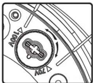
- Select the tap position by adjusting the rotary switch to the desired high impedance value or voice coil bypass mode. The switch is preset to the maximum tap setting in 70.7 V mode.

- Attach grille & bezel seismic restraint to baffle with provided screw.
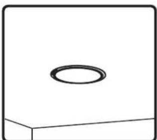
- Attach grille – position the grille over the baffle and allow magnets to attract grille into place. Be sure grille is properly centered over baffle.

- Nail or screw bracket to joists. Secure cover plate and conduit away from hole in bracket.
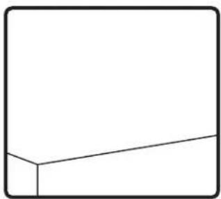
- Complete finish work.

- Use Rotozip or other tool to cut hole.

- Thread signal wire through conduit cover plate. Connect signal wire to 4-pin Euro-block plug. Tighten unused terminal screws. Use inside positive and negative inputs for either voice coil or distributed systems. For daisy chaining, use outside positive and negative terminals. Euroblock must be plugged in for daisy chain to function.
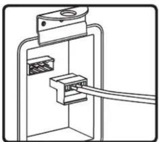
- Insert the Euroblock plug into the Euroblock jack on side panel of speaker and replace conduit cover plate. For UL-compliant installations strain relief (not supplied) may be inserted into hole in conduit cover plate.

- If seismic restraint is required, attach the suspension cable to sheet-metal tab on the side of speaker.
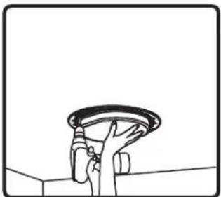
- Insert speaker into mounting hole with installation aid in place. Tighten both bolts located on the baffle face to actuate the mounting wings. Firmly secure both sides – do not over-tighten.
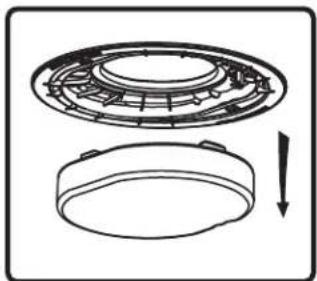
- If not painting the ceiling, remove & discard the paint mask.
- If painting the ceiling after the speaker is installed, leave the paint mask in place until paint is dry.

- Select the tap position by adjusting rotary switch to desired high impedance value or voice coil bypass mode. Switch is preset to maximum tap setting in 70.7 V mode.
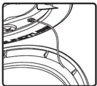
- Attach grille & bezel seismic restraint to baffle with provided screw.
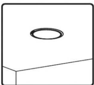
- Attach grille – position the grille over the baffle and allow magnets to attract grille into place. Be sure grille is properly centered over baffle.

Brand : SoundTube
Model : CM1001D
Category : Subwoofer