
MFG 2604 N - Oven Meireles - Free user manual and instructions
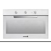
Find the device manual for free MFG 2604 N Meireles in PDF.


| Brand | Meireles |
| Model | MFG 2604 N |
| Product Type | Gas oven with electric grill |
| Power Supply | 230V ~ 50/60 Hz |
| Maximum Power Input | 1640 W |
| Grill Power | 1600 W |
| Oven Burner Power (Butane/Propane) | 2750 W (PCS) |
| Gas Types Supported | Butane (28-30 mbar), Propane (37 mbar), Natural Gas (20 mbar) |
| Oven Temperature Range | 50°C to Max |
| Timer Type | Digital (programmable) or mechanical (120 min max) |
| Oven Functions | Static, Grill, Skewer, Thermostat |
| Skewer Motor | 5 W |
| Oven Light | 15 W |
| Tangential Fan | 20 W |
| Oven Light Bulb Specifications | E14, 15 W or 25 W, high temperature (300°C) |
| Cleaning | Removable side racks, removable inner glass |
| Safety Features | Child lock (indirect via supervision), automatic gas shut-off (thermostat), triple-glazed door |
| Installation Requirements | Omnipolar switch with 3 mm contact gap, independent circuit |
| Weight | Approximately 30-40 kg (typical built-in oven) |
Frequently Asked Questions - MFG 2604 N Meireles
User questions about MFG 2604 N Meireles
0 question about this device. Answer the ones you know or ask your own.
Ask a new question about this device
Download the instructions for your Oven in PDF format for free! Find your manual MFG 2604 N - Meireles and take your electronic device back in hand. On this page are published all the documents necessary for the use of your device. MFG 2604 N by Meireles.
USER MANUAL MFG 2604 N Meireles
MANUAL DE INSTRUÇÕES
INSTRUCTION MANUAL
natural_image
Pure electrical circuit lines without any symbolsnatural_image
Simple line drawing of an oven with a diagonal arrow indicating direction (no text or symbols)
natural_image
Simple line drawing of an oven with a tray and vent, showing a directional arrow (no text or symbols)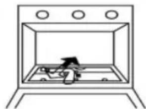
natural_image
Simple line drawing of a person inside a incubator with three circular tops (no text or symbols)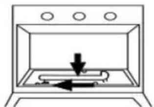
natural_image
Simple line drawing of a stove interior with an arrow indicating downward motion (no text or symbols)3
INSTRUÇÕES PARA O UTILIZADOR
PT
natural_image
Diagram of a mechanical device with a lever and paper plane, no visible text or symbols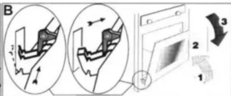
natural_image
Diagram of a light bulb being compressed into a container with arrows indicating motion (no text or symbols)RETIRAR AS GRELHAS LATERAIS DO FORNO
Thank you for choosing our product. Using this appliance is very easy; before installing and using it, you must read this manual carefully, in which you will find the correct instructions for installing, using and maintaining this product.
It is very important that this instruction manual is kept together with the appliance in the event of it being handed over to a different person.
General Warnings
ATTENTION: The appliance and its accessible parts may become hot during use, care must be taken to avoid touching the heating elements.
Children under 8 years of age should be kept away from the appliance, unless they are under adult supervision.
WARNING: Cooking with fat or oil in an oven can be dangerous and could result in a fire. Never attempt to extinguish a fire with water, rather switch off the appliance.
WARNING: risk of fire: Do not store containers or other things inside of the oven.
The appliance gets hot during use, therefore care must be taken to avoid touching the heating elements inside of the oven.
WARNING: accessible parts may become hot during use, therefore small children should be kept away from the appliance.
Do not use abrasive cleaners or sharp metal scrapers to clean the glass on the oven door, as they may scratch the surface, which could result in the glass breaking.
This appliance should not be cleaned with steam cleaning appliances.
WARNING: Make sure that the appliance is switched off before replacing the oven light bulb to prevent the possibility of an electric shock.
This appliance is not intended to be operated by an external timer or remote control system.
This appliance is not intended for use by persons (including children) with reduced physical or mental capacities, or by persons lacking experience or knowledge, unless they have been trained or instructed in the use of the appliance by a responsible person for their safety.
Children should be supervised to ensure that they do not play with the appliance.
Cleaning and maintenance should not be carried out by children.
For installation of the oven's side racks see page 18, maintenance and cleaning instructions.
This appliance must not be installed behind a decorative door to prevent overheating.
The installation of the appliance must be carried out by qualified personnel and according to the technical characteristics of the cooker (see affixed characteristics plate).
In the electrical connection, a means of switching the oven off from the mains power supply according to the installation rules must be provided on the fixed pipe.
An omnipolar switch with minimum opening between the 3mm contacts, which is suitable for the load and complies with the safety regulations in force, must be installed between the appliance and the mains.
Before carrying out any maintenance or cleaning works, switch the oven off from the mains power supply activating the protective device.
If the appliance's power cord is damaged, it must be replaced by the manufacturer or qualified persons to avoid a hazard.
Placement and Installation
The dimensions of the oven are mentioned in the figures on page 19.
For correct operation of the oven, the indications and dimensions indicated in the figures on page. 19 and 20 must be observed, namely:
Existence of fresh air flow in the baseboard and in the top part of the furniture according to details A and E.
Minimum distance from the oven ceiling to the bottom of a plate situated on top of it according to detail B.
Minimum distance from furnace door to adjacent furniture cabinet door according to detail C.
Circulation of fresh air according to detail D
Insert the oven into the opening of the furniture by supporting it at the base and pushing it until it touches.
Open the oven door and secure the oven to the furniture cabinet using the four screws provided.
The oven's electrical connection must be independent of any other connection.
The cabinet furniture materials should be able to withstand temperatures up to 90°C
Before starting to use the oven, we recommend that you:
- Remove the protective film covering the oven door glass (if there is one):
- Heat the oven with no food inside at the maximum temperature for about 45 minutes (to eliminate any unpleasant odours and smoke caused by manufacturing residues and thermal insulation);
- Thoroughly clean the inside of the oven with soap and water and thoroughly rinse with clean water.
ENVIRONMENTAL ADVICE
 | Do not throw away your appliance's packaging. This can be recycled. Take it to a recycling bin. |
 | This symbol on the product indicates that the product cannot be treated as household waste. Instead, it should be taken to the selective collection centre for the recycling of electrical and electronic equipment. By ensuring proper disposal of this product, it will help to prevent possible negative consequences for the environment and public health, which could otherwise be caused by incorrect handling of the product. For more detailed information on the recycling of this product, please contact your local municipal services, the selective collection centre in your area of residence or the shop where you purchased the product. |
 | The symbol on the product's label shows that the product contains a light source.In point 8. Cleaning and Maintenance Instructions you can see information about this light source and how to replace it. |
2. INSTRUCTIONS FOR THE INSTALLER
PT
ELECTRICAL CONNECTION
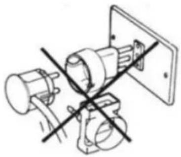
The apparatus is provided with a power cable and is predisposed to operate with alternating current with the voltage indicated on the plate containing the appliance's characteristic data which is placed on a label on the appliance. The "Earth" conductor of the electric cable is characterised by the yellow/green colours
CONNECTING THE POWER CORD TO THE MAINS POWER SUPPLY
The installation of the appliance must be carried out by qualified personnel familiar with the installation standards and regulations in force.
natural_image
Technical line drawing of electrical circuit components with no visible text or symbolsBefore connecting the appliance, check that the electrical installation and the protective device comply with the technical characteristics of the appliance.
To connect the appliance to the mains, an omnipolar switch with a minimum opening of 3mm between the contacts, which is suitable for the load and corresponds to the safety regulations in force, must be installed between the appliance and the mains.
The earth conductor, identified by its green/yellow colours, must not be disturbed by the switch.
The manufacturer is not liable for any direct or indirect damages that may be caused by an erroneous installation or connection.
It is therefore necessary that all operations relating to the installation and the electrical connection are carried out by specialised personnel and that the work is done in accordance with local and general standards in force.
2. INSTRUCTIONS FOR THE INSTALLER
PT
Important: When the appliance has just been installed, check the perfect seal of all the connections using a soapy water solution and never a flame.
Warning: Use of the gas appliance produces heat and humidity in the room in which it is installed. Therefore check that the room is well ventilated by keeping the natural ventilation openings open or by installing an exhaust hood with the respective chimney.
Adapting the oven burner to various types of gas.
In order to adapt the appliance to a type of gas other than the one for which it is intended (for this purpose see the label on the packaging and the appliance), the following operations must be carried out:
- Open the oven door and remove all accessories inside (basin, racks, etc.).
- Remove the bottom part of the oven, lifting it and removing it.
- Remove the burner by loosening the screws on the front fixing bracket.
- Remove the burner by loosening the screws on the bracket that secures it to the front.

natural_image
Simple line drawing of an oven with a diagonal arrow and tray, no text or symbols present
natural_image
Simple line drawing of an oven with a tray and vent, showing a directional arrow (no text or symbols)
natural_image
Simple line drawing of a person inside an oven with three circular tops (no text or symbols)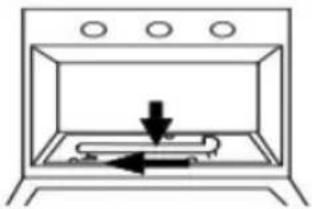
natural_image
Simple line drawing of a toaster oven with a downward arrow indicating cooling or ventilation (no text or symbols)- Remove the nozzle from its holder using a 10mm wrench and replace it with the suitable one for the gas which the appliance will be working on (see "Characteristics table").
- Reassemble the various parts by proceeding in the opposite direction to the disassembly, making sure to replace the regulation label on the appliance with that relating to the new type of gas (supplied).
In the case where the gas pressure used is different (or variable) than the one anticipated, an appropriate pressure regulator must be installed in the inlet pipe and in accordance with local regulations.
natural_image
Technical line drawing of a mechanical flange component (no text or symbols)2. INSTRUCTIONS FOR THE INSTALLER
PT
TRANSFORMATION FOR DIFFERENT GASES
Adjusting the minimum
Reduced flame control was carried out at the factory. After the injector has been replaced to adapt it to the type of gas available or following particular conditions of the mains pressure, it may be necessary to re-adjust the minimum flame.
The operations required to perform such an operation are as follows:
- Remove all the accessories from the inside of the oven, including the bottom plate.
- Turn the oven on by turning the thermostat knob to the maximum following the instructions in the respective paragraph and gently close the oven door.
- Wait for about 10 minutes and then access the thermostat bypass screw using an appropriate screwdriver and after having removed the knob and threaded ring. The by-pass screw may be on the left (pos. A) or at the top (pos. B).
- Position the thermostat rod in accordance with the minimum flame position.
- Screw or unscrew the by-pass screw to decrease or increase the flame respectively, until a small, regular flame is obtained.
- Refit the knob and the threaded ring and check that the flame does not go out quickly going from the maximum flame to the minimum.
- Also check that the setting obtained is sufficient to maintain the heating of the probe.
- Turn off the burner and, after cooling, re-insert the bottom of the oven and the previously removed accessories. The setting for liquid gas (B/P) must be made by fully tightening the bypass screw.

THE BURNER DOES NOT REQUIRES A PRIMARY AIR ADJUSTMENT.
3. INSTRUCTIONS FOR THE USER
PT
The control knob allows you to select the following oven functions: the following oven functions:
The purchased oven may not have all the functions, in this context you must turn the knob to the functions on your oven.
Static Oven:
 | The oven light is on and no electrical resistor is connected. The light is always on while the oven is in operation |
 | Only the grill resistor is on. |
 | It is in the skewer position. |
The thermostat knob allows you to select temperatures between 50° and MAX  | |
USING THE GAS OVEN AND ELECTRIC GRILL
For safety reasons, the design of the appliance does not allow the simultaneous use of a gas oven and electric grill in mixed models. To use the electric grill, turn the knob clockwise by pushing the point towards the word grill or the 📄 symbol on the panel.
GAS OVEN
To light the oven proceed as follows:
Press the igniter button ✪ or open the oven door and bring a flame to the burner through the base of the oven.
Press the oven valve knob and turn it counter-clockwise to the position shown on the panel.
Keep the knob pressed for ab out 10 seconds.
After this time release the oven knob, which should remain lit. If not, repeat the steps. To decrease the power, turn the knob to the "minimum" position.

natural_image
Line drawing of a hand placing a small object into a kitchen appliance (no text or symbols)To turn off the oven, turn the knob clockwise to the "off" position, represented by a black circle on the panel.
THERMOSTAT GAS OVEN
These models have a thermostatic gas valve, which allows you to select the desired temperature inside the oven. In these models the consumption of gas is reduced automatically as soon as the inside of the oven reaches the selected temperature. The operation of this oven is carried out by turning the knob counterclockwise, choosing the desired temperature.
Certain models have a rotating skewer, in this case, read the following instructions:
| In the models with a rotating skewer, feed the food onto the skewer so that the weight is centred, taking care to fit and tighten the two forks.Position the skewer holder by inserting the two ends of the holder into the sides of the oven. | 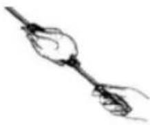 |
| Insert the free end of the skewer into the motor hole in the back wall of the oven, checking that the skewer is positioned correctly in the motor.Lean the skewer collar, which is on the handle end, on the holder and take the handle off of the skewer, this serves to facilitate the removal of the skewer after cooking. |  |
| On certain models, attach the skewer to the rack and push the rack into the oven, making sure that the skewer is properly fitted into the motor.Place the fat collection tray in the lowest part of the oven. |  |
4. INSTRUCTIONS FOR COOKING
PT
4.1 BAKING IN THE OVEN
To bake well, you must preheat the oven to the desired temperature. Only in the case of very fatty meats should you use the oven cold. Never use low-edge containers or a tray as a baking tray in order to avoid dirtying the oven walls as much as possible, limiting how much fat splashes out, as it burns quickly and causes smoke. Use high-edged containers, preferably made from clay, placed on the rack at about half the height of the oven. The thermostat setting and the operating time, for instance, are indicated in the corresponding table at the end of this booklet. Baking times may vary depending on the type of food, its homogeneity and its size. We are sure that after having carried out some tests the experience gained will suggest possible variations in the values indicated in the operating times table.
Preheat the oven to the desired temperature before placing the food in the oven.
| Never use the juice collection tray as a baking tray. This causes a fire risk due to the accumulation of juices at the bottom, and the high temperatures that are felt inside the oven. In addition it burns the juices, produces smoke and splashes the fat.The rack tray should be positioned halfway up the oven with the food in a high-edged baking tray | 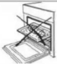 |
| When positioning the rack in the grooves closest or farthest from the grill, you must take the thickness and type of food into consideration.Whenever you use the rack to put the food in the oven, place the collection tray on the bottom to catch the juices. | 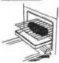 |
Some practical tips for saving electricity
The oven can be turned off a few minutes before the food is completely baked; the residual temperature will be enough to finish the baking.
Open the oven door as little as possible; to check the cooking progress, look through the oven glass door (the oven light is always on).
5. DIGITAL CLOCK / TIMER
PT
20:46
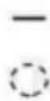


SET THE TIME
Press the + and - buttons at the same time. The dot between the hour and minute indicator flashes. Set the time pressing the + and - buttons at the same time. Pressing these buttons at any time lets you make quick adjustments. Hold down the + and - buttons at the same time for a while, until the dot between the hour and the minutes flashes, allowing you to adjust part of the hours on the display.
SET THE TIMER
Press the + button. The display will show '0.00' and the bell symbol will flash. You can set the timer using the + and - buttons.
After 6 seconds the bell symbol will remain lit. The timer will start counting down. The minute increments are from 10 seconds to 99 minutes and 50 seconds, after which the display will show one hour and 40 minutes, the setting will be in 1 minute steps.
Note: To cancel the timer programme, set the timer time to 0.00.
TURNING OFF THE TIMER BELL
When the timer counts down, the display will show the current time. The bell symbol starts flashing and an audible alarm rings. If it is not turned off, it will ring for seven minutes.
Press any key to stop the alarm ringing.
ADJUSTING THE SOUND
You can adjust the timer alarm tone as follows:
1) - by pressing the (-) button you can hear the sound that is currently set
2) - release the (-) button and then press it again, you can hear the next available sound (total of 3)
3) - the last sound heard will be set
TIMER (models with)
To use the timer you must load the bell by turning the knob one turn clockwise; then turn counter-clockwise until the desired operating time (max.120minutes) is reached.
After the pre-set time has been reached the bell starts to ring. The timer bell does not stop the oven functioning.
- TABLE OF OVEN TIMES
PT
| Type of food | Rack groove no. | Oven Temperature °C | Time in minutes |
| COOKED FOODS | |||
| Baked with a lot of cooking | 2 | 220-250 | Seg. quant. |
| Baked with short cooking | 2 | 225-250 | 50-60 |
| Winged animals (guinea fowl, duck, etc.) | 1 | 210-250 | 150-180 |
| Poultry meat | 2 | 225-250 | 50 -60 |
| Game | 1 | 200-225 | Seg. quant. |
| Fish | 1 | 180-200 | 20-25 |
| CAKES | |||
| Christmas pudding | At the bottom | 160- 200 | 60-70 |
| Plum-cake | At the bottom | 170-200 | 90 -100 |
| Orange cake | At the bottom | 170-22 | 80 -100 |
| Finger biscuits | 2 | 200 | 40 -45 |
| Croissants | 2 | 215-230 | 35-40 |
| Barley bread | 2 | 215 | 30-40 |
| Sponge cake | 2 | 2002-215 | 30-35 |
| Meringues | 1 | 140 | 60-80 |
| Sweet dough | 2 | 2002-215 | 30 |
| Fruit tarts (puff pastry) | 2 | 250 | 30-35 |
| Fruit tarts (shortcrust pastry) | 2 | 230 | 20-30 |
- TABLE OF GRILL TIMES
| Type of food | Kg | Rack groove no. | Oven Temperature °C | Pre-heating time in minutes | Time in minutes |
| Veal Chops | 1 | 3 | 250 | 5 | 8-10 |
| Lamb Chops | 1 | 3 | 250 | 5 | 12-15 |
| Liver | 1 | 3 | 250 | 5 | 10-12 |
| Minced beef parcels | 1 | 3 | 250 | 5 | 12-15 |
| Veal Heart | 1 | 3 | 250 | 5 | 12-15 |
| Netted meat | 1 | 3 | 250 | 5 | 20-25 |
| Half of a chicken | -- | 3 | 250 | 5 | 20-25 |
| Haddock fillets | -- | 3 | 250 | 5 | 12-15 |
| Stuffed tomatoes | -- | 3 | 250 | 5 | 10-12 |
8. MAINTENANCE AND CLEANING INSTRUCTIONS
PT
IMPORTANT: After each clean, the oven must be switched on at the maximum temperature and for a sufficient time to evaporate the moisture resulting from the clean.
Doing this increases the life of your oven, minimising the probability of corrosion caused by moisture.
General Cleaning
Clean the oven after each use to maintain the shine of the enamelled parts for as long as possible. After allowing the oven to cool down, you can easily remove the fatty deposits using a sponge or a damp cloth with warm water and detergents or possibly a specific product that is commercially available. Do not use abrasive cloths or sponges, which can irreparably damage the enamel. After use, rinse the stainless steel parts with clean water and then wipe them with a cloth or chamois leather. In the case of persistent stains use the normal, non-abrasive detergents, specific products for stainless steel or some hot vinegar.
Cooking with fat or oil in an oven can be dangerous as it could result in a fire, therefore it must be cleaned after each use.
Cleaning the oven door
To clean the oven door you can remove the inner glass, clean and replace it.
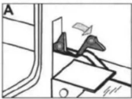
For safety reasons before removing the inner glass for cleaning, remove the oven door as follows:
natural_image
Diagram of a mechanical device with a lever and paperboard, no visible text or symbols
1 - Open the oven door completely
2 - Lift the trestles of the hinges using your thumb and index finger by turning them completely towards you (fig A 13 - Push the door up to the closing position until it rests on the trestles. So that the hinge's spring is locked.
By continuing to close the oven door, the hinges of the respective connections, which are attached to the oven structure, can be unhooked (sequences 1, 2, 3 of fig.B).
To mount the door, follow the steps above in reverse.
Removing and re-inserting the inner glass
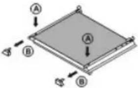 | - Press tab (A). Simultaneously, remove the upper caps (B) |
 | - Slide the inner glass (C) until it releases from the lower caps (D) - Remove the glass Clean the glass using hot water only, avoid rough cloths |
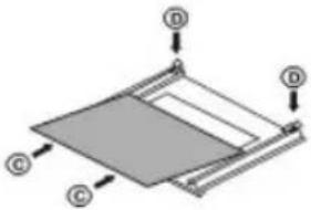 | - Place the glass on the side supports - Slide the glass until it fits into the grooves of the lower caps (D) |
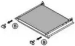 | - Re-position the upper caps (B) |
REPLACING THE OVEN LIGHT BULB
ATTENTION: Disconnect the appliance from the power supply before replacing the bulb, activating the protection device to avoid the possibility of electric shock.
After disconnecting the oven from the power supply, unscrew the glass cover of the light and the bulb itself, replacing it with one that is suitable for high temperatures (300°C), with the following characteristics:
Power: 15 W/ 25 W (according to the model)
Screw thread base: E14
Replace the glass cover and switch on the appliance.

natural_image
Diagram of a spray gun with a container and directional arrows indicating motion (no text or symbols)REMOVING THE OVEN'S SIDE RACKS
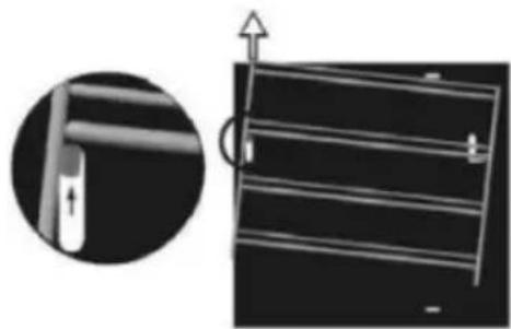
These chrome side racks can be removed to facilitate cleaning. To do this, follow the instructions from 1. to 3. to disassemble the oven racks. To reassemble, follow the instructions from 3. to 1.
natural_image
Diagram showing a mechanical component with an inset close-up of a pin inserted into a bracket (no text or symbols)
natural_image
Technical diagrams showing mechanical assembly steps with cross-sectional views (no text or symbols)-
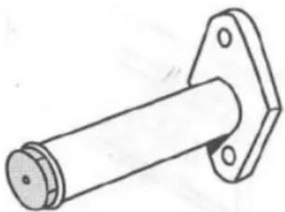
Lift the rack vertically and remove the pin placed in the front slot on the side of the oven.
-
Move the rack in the direction indicated so that it unhooks from the groove near the back of the oven
-
Lift the rack vertically and remove the pin placed in the back slot on the side of the oven.
The stainless steel slides that support the enamelled baking trays can be removed and placed on the 3 levels of the side racks.
9. PRODUCT CHECKS
PT
The manufacturer certifies that this appliance has been subject to the following checks:
- Operation of the electrical components.
- Dielectric strength.
- Earth circuit resistance.
- Aesthetic checks
Manufacturer Address: Rua D. Afonso Henriques, 235-4585-322 Gandra (Paredes)
You can access the information in our booklets on our website www.meireles.pt
10.
DIMENSIONS OF FURNITURE / OVENS
PT

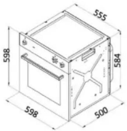
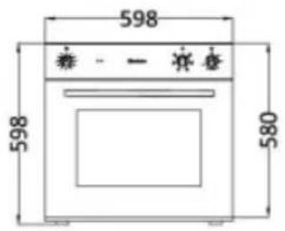
Vista frontal

Vista lateral

Vista superior


The manufacturer reserves the right to make changes to the appliances, without these changes affecting their operation or safety.
11.
TECHNICAL CHARACTERISTICS
PT
Characteristics Table
| CAT.II 2H3 + | ||||||||
| BUTANE GAS | PROPANE GAS | NATURAL GAS | ||||||
| Nominal working pressure, mbar | 28 -30 | 37 | 20 | |||||
| Maximum working pressure, mbar | 35 | 45 | 25 | |||||
| Minimum working pressure, mbar | 25 | 25 | 17 | |||||
| Power, W (P.C.S) | Flow | Nozzle | Flow | Nozzle | Flow | |||
| Burners | Normal | Minimum | g/h | mm | g/h | mm | L/h | |
| Oven | 2750 | 1100 | 200 | 0.80 | 197 | 1.20 | 262 | |
Electrical characteristics of the 60cm oven
| Powers when applicable to your oven model |
| Power supply |
| Electrical part = ~ 230V - 50/60 Hz |
| Grill Resistance = 1600W |
| Skewer Motor = 5 W |
| Oven light = 15 W |
| Tangential Fan = 20 W |
| maxP = 1640 W |
ÍNDICE
natural_image
Technical line drawing of a mechanical assembly with intersecting lines (no text or symbols)natural_image
Technical line drawing of a mechanical flange component (no text or symbols)natural_image
Line drawing of a hand placing a component into a kitchen appliance (no text or symbols)natural_image
Diagram of a mechanical device with lever and paperboard, no visible text or symbols
natural_image
Diagram of a spray gun with rotating components, showing fluid flow direction (no text or labels)RETIRAR LAS PARRILLAS LATERALES DEL HORNO
natural_image
Diagram showing a mechanical component with an inset close-up of a pin inserted into a bracket (no text or symbols)
natural_image
Technical diagram showing mechanical assembly steps with cross-sectional views (no text or labels)natural_image
Technical line drawing of electrical connectors and wiring (no text or symbols)natural_image
Technical line drawing of a cylindrical mechanical component with flanged ends and a central shaft (no text or symbols)natural_image
Line drawing of a hand opening a microwave oven with control buttons (no text or symbols)natural_image
Diagram of a mechanical device with a lever and paperboard, no visible text or symbols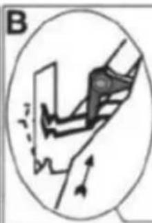
natural_image
Diagram of a hand holding a tool with motion arrows indicating movement (no text or symbols)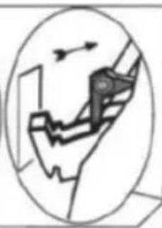
natural_image
Diagram of a mechanical device inside an oval frame, showing motion direction with arrows (no text or labels)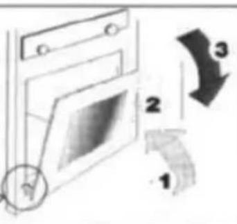
natural_image
Diagram of a spray gun with rotating components and directional arrows indicating motion (no text or symbols)natural_image
Diagram showing a mechanical component with an inset close-up of its part, no visible text or symbols
natural_image
Technical diagram showing a mechanical assembly with a left-side view and a close-up of a vertical rod (no text or symbols present)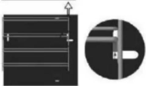
natural_image
Diagram showing a structural component with an upward arrow and a magnified detail of a vertical pipe or pipe fitting (no text or symbols)
- INSTRUÇÕES PARA O UTILIZADOR
- RETIRAR AS GRELHAS LATERAIS DO FORNO
- General Warnings
- Placement and Installation
- Circulation of fresh air according to detail D
- Before starting to use the oven, we recommend that you:
- ENVIRONMENTAL ADVICE
- INSTRUCTIONS FOR THE INSTALLER
- ELECTRICAL CONNECTION
- CONNECTING THE POWER CORD TO THE MAINS POWER SUPPLY
- Adapting the oven burner to various types of gas.
- TRANSFORMATION FOR DIFFERENT GASES
- Adjusting the minimum
- INSTRUCTIONS FOR THE USER
- Static Oven:
- USING THE GAS OVEN AND ELECTRIC GRILL
- GAS OVEN
- THERMOSTAT GAS OVEN
- INSTRUCTIONS FOR COOKING
- BAKING IN THE OVEN
- Some practical tips for saving electricity
- DIGITAL CLOCK / TIMER
- 20:46
- SET THE TIME
- SET THE TIMER
- TURNING OFF THE TIMER BELL
- ADJUSTING THE SOUND
- TIMER (models with)
- MAINTENANCE AND CLEANING INSTRUCTIONS
- General Cleaning
- Cleaning the oven door
- REPLACING THE OVEN LIGHT BULB
- REMOVING THE OVEN'S SIDE RACKS
- PRODUCT CHECKS
- ÍNDICE
- RETIRAR LAS PARRILLAS LATERALES DEL HORNO
Brand : Meireles
Model : MFG 2604 N
Category : Oven