
CPSPV12000ETL-S - Solar panel CyberPower - Free user manual and instructions
Find the device manual for free CPSPV12000ETL-S CyberPower in PDF.


| Brand | CyberPower |
| Model | CPSPV12000ETL-S |
| Product Type | Solar Panel |
| Cell Type | Monocrystalline Silicon |
| Power Output | 400 W |
| Dimensions (LxWxH) | 1750 x 1038 x 35 mm |
| Weight | 20 kg |
| Efficiency | 20% |
| Operating Temperature | -40°C to +85°C |
| Max System Voltage | 1500 V DC |
| Frame Material | Anodized Aluminum |
| Glass | Tempered Glass |
| Junction Box Protection | IP68 |
| Cable | 4 mm², 1 m |
| Connectors | MC4 Compatible |
| Warranty | 25 Years Performance |
| Certifications | TUV, IEC, CE |
| Maintenance | Clean with water and soft cloth; avoid abrasive materials |
| Safety | Class II double insulation; anti-reflective coating |
| Spare Parts | Available from authorized dealers: junction box, cables, connectors |
Frequently Asked Questions - CPSPV12000ETL-S CyberPower
User questions about CPSPV12000ETL-S CyberPower
0 question about this device. Answer the ones you know or ask your own.
Ask a new question about this device
Download the instructions for your Solar panel in PDF format for free! Find your manual CPSPV12000ETL-S - CyberPower and take your electronic device back in hand. On this page are published all the documents necessary for the use of your device. CPSPV12000ETL-S by CyberPower.
USER MANUAL CPSPV12000ETL-S CyberPower
Reliability. Quality. Value.
CPSPV7000ETL-S
CPSPV8000ETL-S
CPSPV9000ETL-S
CPSPV10000ETL-S
CPSPV11000ETL-S
CPSPV12000ETL-S
CPSPV15000ETL-S
User's Manual

CyberPower Systems Inc.
www.cyberpower.com
Index
CONTENTS
1. INFORMATION ON THIS MANUAL....3
1.1 VALIDITY....3
1.2 TARGET GROUND 3
1.3 SYMBOLS USED....4
2. SAFETY 5
2.1 INTENDED USE....5
2.2 SAFETY PRECAUTIONS 6
2.3 ASSEMBLY WARNINGS....6
2.4 ELECTRICAL CONNECTION WARNINGS 6
2.5 OPERATION WARNINGS....7
3. PRODUCT DESCRIPTION 9
3.1 CPS MINI CENTRAL SERIES OVERVIEW....9
3.2 SIZE AND WEIGHT....10
3.3 TYPE LABEL 11
3.4 SPECIFICATION OF CYBERPOWER MINI CENTRAL SERIES....12
3.5 TRANSPORTATION....16
3.6 STORAGE OF INVERTER 16
3.7 THE ADVANTAGE OF THE CPS MINI CENTRAL INVERTERS....16
4. UNPACKING 17
5. INSTALLATION 18
5.1 SAFETY INSTRUCTION 18
5.2 SELECTING THE INSTALLATION LOCATION....19
5.3 INSTALLATION GUIDE....21
6. ELECTRIC CONNECTION 24
6.1 AC CONNECTION....24
6.2 DC CONNECTION....26
6.3 GROUNDING 27
6.4 GRID TYPE....28
7. START-UP AND SHUT DOWN THE INVERTER....29
7.1 START-UP THE INVERTER....29
7.2 SHUT DOWN THE INVERTER....30
8. COMMISSIONING 31
8.1 CHECK BEFORE COMMISSIONING 31
8.2 COMMISSION THE INVERTER....31
8.3 OPERATION MODES....31
9. DISPLAY SETTING 33
9.1 LED DISPLAY 33
9.2 INVERTER INFORMATION....33
9.3 DISPLAY OPERATION 34
- COMMUNICATION 38
10.1 USING 'SOLAR POWER SETUP_3P' TO UPDATE FIRMWARE & MONITOR INVERTER....38
10.2 MONITOR THE INVERTERS 39
10.3 RS485 CABLE CONNECTION 40
- TROUBLE SHOOTING....41
- CERTIFICATES 42
- CONTACT....42
1. Informaon on this Manual
1.1 Validity
This installaon guide contains installaon, commissioning, communicaon, trouble shoong. Informaon of CPS Mini Central series:
CPSPV7000ETL-S
CPSPV8000ETL-S
CPSPV9000ETL-S
CPSPV10000ETL-S
CPSPV11000ETL-S
CPSPV12000ETL-S
CPSPV15000ETL-S
With this installaon guide, users are able to install and operate the inverters easily. This manual does not cover any details concerning equipment connected to the CPS Mini Central series. Store this manual where accessible at all mes.
1.2 Target Ground
This manual is for qualified persons such as PV system installers or electricians. Notes: For possible changes in this manual, CyberPower Systems, Inc. accepts no responsibilities to inform the users
1.3 Symbols Used
The following types of safety instrucons and general informaon appear in this document as described below:
| Symbol | descripon | |
 | Read the manual | |
 | DANGER | DANGER indicates a hazardous situaon which, if not avoided, will result in death or serious injury. |
 | WARNING | WARNING indicates a hazardous situaon which, if not avoided, could result in death or serious injury. |
 | CAUTION | CAUTION indicates a hazardous situaon which, if not avoided, could result in minor or moderate injury. |
 | NOTICE | NOTICE indicates a situaon which, if not avoided, could result in property damage. |
 | Information | Informaon that you must read and know to ensure opmal operaon of the system. |
2. Safety
2.1 Intended Use
CPS Mini Central series inverters are to be used solely to feed solar energy converted photovoltaically into the public grid. CPS Mini Central series inverters are mul-string inverters with mul-MPP trackers, which mean they are able to connect to dierent PV module arrays. The equipment may only be operated in compliance with its intended use.
Grid-ed PV system Overview:
![graph LR A["PV Panel"] --> B["String Fuse"] C["PV Inverter"] --> B D["AC Breaker"] --> E["Public Grid"] B --> F["Image 1"] B --> G["Image 2"] B --> H["Image 3"]](/content/2026/05/997765/images/d476534bae5da9b6fc70d811f1c219e7a989df8f8f665172a9180758ae6c5a4c.jpg)
Fig2.1
The inverter may only be operated with a permanent conncon to the public power grid. The inverter is not intended for mobile use. Any other or additional use is not considered as intended use. The manufacturer is not responsible for any damages resulting from unintended use. Damage caused by such unintended use is at the sole risk of the operator.
As drawings shown above, a complete Grid-ed PV system consists of PV modules, PV inverters, public grid and other components. Moreover, PV inverters always act as key components.
PV modules Capacive Discharge Currents:
PV modules with large capacities relave to earth, such as thin-lm PV modules with cells on a metallic substrate, may only be used if their coupling capacity does not exceed 5000nF. During feed-in operaon, a leakage current ows from the cells to earth, the size of which depends on the manner in which the PV modules are installed (e.g. foil on metal roof) and on the weather (rain, snow). This "normal" leakage current may not exceed 300mA due to the fact that the inverter would otherwise automacally disconnect from the electricity grid as a protecve measure.

Information
If PV modules of the PV system require POSITIVE or NEGATIVE grounding, , please contact CyberPower Systems, Inc. for technical support before installaon.
2.2 Safety Precauons
The CPS Mini Central series is designed and tested according to internaonal safety requirements; however, certain safety precautions must be observed when installing and operating this inverter. Read and follow all instrucons, cauons and warnings in this installaon manual.
2.3 Assembly Warnings
 WARNING WARNING | Prior to installaon, inspect the unit to ensure absence of any transport or handling damage, which could aect insulaon integrity or safety clearances; failure to do so could result in safety hazards.Unauthorized removal of necessary protecons, improper use, incorrect installaon and operaon may lead to serious safety, shock hazards or equipment damage.In order to minimize the potenal of a shock hazard due to hazardous voltages, cover the enre solar array with dark material prior to connecng the array to any equipment. |
 CAUTION CAUTION | Grounding the PV modules: Comply with the local requirements for grounding the PV modules frame and the PV generator.CyberPower strongly recommends grounding the generator frame in order to have opmal earth protecon to PV generang system and personnel. |
2.4 Electrical Connecon Warnings
 DANGER DANGER | Some components in the inverter are live. Touching live components can result in serious injury or death.Danger to life due to high voltages in the inverterAll work on the inverter may be carried out by qualified personnel only.The appliance is not to be used by children or persons with reduced physical, sensory, mental capabilities, or lack of experience and knowledge, unless they have been given supervision or instrucon. | |
 WARNING WARNING | Make all electrical conncons (e.g. conductor terminaon, fuses, PE conncon, etc.) in accordance with prevailing regulaons.The CPS Mini Central series may only be operated with PV generators (modules and cabling) with protecve insulaon. Do not connect any source of energy other than PV modules to the CPS Mini Central series.Please read this manual carefully, the manufacturer or supplier is | |
WARNING | not responsible for damage caused by incorrect operaon, installaon, wiring, transport, etc. | |
 CAUTION CAUTION | The CPS Mini Central series is to be used solely to feed solar energy converted photovoltaic into the public grid. The inverter is suitable for mounng both indoors and outdoors.You can use the AC current generated as follows: | |
| House grid: | Energy ows into the house grid. The consumers consume the energy with household devices or lighng. The le energy is fed into the public grid. When the CPS Mini Central series do not generate any energy, e.g., at night, the consumers which are connected are supplied by the public grid. The energy displayed on the LCD of inverter is for reference only. When energy is fed into the public grid, the wameter spins backwards. Note that the wameter should be bi-direcon type under such applicaon. | |
| Public grid: | Energy is fed directly into the public grid. The CPS Mini Central series need install a separate wameter. | |
2.5 Operaon Warnings
 WARNING WARNING | ➢ Ensure all covers and doors are closed and secure during operaon.➢ Although designed to meet all safety requirements, some parts and surfaces of Inverter are sll hot during operaon. To reduce the risk of injury, do not touch the heat sink at the back of the PV-Inverter or nearby surfaces while Inverter is operang.➢ Incorrect sizing of the PV array may result in over input voltages which could destroy the inverter. The inverter display will read the error message “PV Voltage High”● Turn the rotary switch of the DC Disconnect to the O posion immediately.● Contact installer. |
 CAUTION CAUTION | ➢ All operaons regarding transport, installaon and start-up, including maintenance must be operated by qualified, trained personnel and in compliance with all prevailing codes and regulaons.➢ When the inverter been disconnected from the power network, to take care those parts remaining charged with hazardous energy to human body. To prevent electric shock, comply with all corresponding safety symbols and markings presented on the unit and manual.➢ When inverter setup locaon is quit near sensitive electric equipment, such as radio or television, electromagnec interfere |
 CAUTION CAUTION | might be happened despite inverter had complied emission limit. In this case, the operator is obliged to take proper acon to improve the situaon. |
2.6 Symbols on the inverter
| Symbol | Explanaon |
 | Refer to operaon instrucon |
 | Cauon, risk of electrical shock |
 | Cauon, hot surface |
 | Earth (ground) terminal |
 | Cauon, risk of electrical shock.Energy stored discharge me. |
 | Direct Current (DC) |
 | Alternang Current (AC) |
 | CE mark.The inverter complies with the instrucon of EC guidelines. |
3. Product Descripon
3.1 CPS Mini Central series overview

| Posion | Descripon | Posion | Descripon |
| A | LCD | F | DC Switch |
| B | LED | G | PV input terminals |
| C | RS232 | H | Serial Number |
| D | AC Output Heat sink | I | Type label |
| E | RS485 |
Pront Panel (Item A): LCD & LED
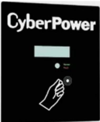
| Symbol | Descripon | Explanaon | |
 | Knock symbol | Indicates for display operaon. | |
 | LED indicator | Constant Green | Operaon |
| Flashing Green | Count Down | ||
| Constant Red | 1、Fault--contact installer2、Standby module | ||
| Flashing Red | 1、Soware update | ||
3.2 Size and weight
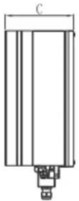

Fig3.4
| A(mm) | B(mm) | C(mm) | D(mm) | Weight(kg) | |
| CPSPV7000ETL-SCPSPV8000ETL-SCPSPV9000ETL-SCPSPV10000ETL-SCPSPV11000ETL-S | 393 | 480 | 200 | 488 | 22 |
| CPSPV12000ETL-SCPSPV15000ETL-S | 393 | 480 | 200 | 488 | 23.5 |
3.3 Type label
The type labels provide a unique idencaon of the inverter (The type of product, Device-specific characteriscs, Cercates and approvals). The type labels are on the right-hand side of the enclosure.
| CyberPower | |
| Model Name | CPSPV/7000ETL-S |
| Max.DC voltage | 1000V |
| DC voltage range | 160V-1000V |
| Full load voltage range | 320V-850V |
| Max input current | 11.5A*2 |
| Max.output power | 7kW/7.7kVA |
| Nominal output power | 7kW/7.7kVA |
| Nominal output current | 10.1 a.c.A |
| Nominal output voltage | 230V/400V(3/N/PE) |
| Nominal AC Frequency | 50Hz/60Hz |
| Power Factor | 0.8leading-0.8laging |
| Safety Level | Class I |
| OVC | III |
| Protection Degree | IP65 |
| Operation ambient temperature | -25°C ~ +60°C |
| CyberPower | |
| Model Name | CPSPV/8000ETL-S |
| Max.DC voltage | 1000V |
| DC voltage range | 160V-1000V |
| Full load voltage range | 360V-550V |
| Max.input current | 11.5A*2 |
| Max.output power | 8kW/8.8kVA |
| Nominal output power | 8kW/8.8kVA |
| Nominal output current | 11.6 a.c.A |
| Nominal output voltage | 230V/400V(3/N/PE) |
| Nominal AC Frequency | 50Hz/60Hz |
| Power Factor | 0.8leading-0.8laging |
| Safety Level | Class I |
| OVC | III |
| Protection Degree | IP65 |
| Operation ambient temperature | -25°C ~ +60°C |
| CyberPower | |
| Model Name | CPSPV9000ETL-S |
| Max.DC voltage | 1000V |
| DC voltage range | 160V-1000V |
| Full load voltage range | 400V-850V |
| Max.input current | 11.5A*2 |
| Max.output power | 9kW/9.9kVA |
| Nominal output power | 9kW/9.9kVA |
| Nominal output current | 13 a.c.A |
| Nominal output voltage | 230V/400V(3/N/PE) |
| Nominal AC Frequency | 50Hz/60Hz |
| Power Factor | 0.8leading-0.8laging |
| Safety Level | Class I |
| OVC | III |
| Protection Degree | IP65 |
| Operation ambient temperature | -25°C ~ +60°C |
| CyberPower | |
| Model Name | CPSPV10000ETL-S |
| Max.DC voltage | 1000V |
| DC voltage range | 160V-1000V |
| Full load voltage range | 450V-850V |
| Max.input current | 13A*2 |
| Max.output power | 10kW/11kVA |
| Nominal output power | 10kW/11kVA |
| Nominal output current | 14.5 a.c.A |
| Nominal output voltage | 230V/400V(3/N/PE) |
| Nominal AC Frequency | 50Hz/60Hz |
| Power Factor | 0.8leading-0.8laging |
| Safety Level | Class I |
| OVC | III |
| Protection Degree | IP65 |
| Operation ambient temperature | -25°C ~ +60°C |
| CyberPower | |
| Model Name | CPSPV/11000ETL-S |
| Max.DC voltage | 1000V |
| DC voltage range | 160V-1000V |
| Full load voltage range | 450V-850V |
| Max.input current | 13A*2 |
| Max.output power | 11kW/12.1kVA |
| Nominal output power | 11kW/12.1kVA |
| Nominal output current | 15.9 a.c.A |
| Nominal output voltage | 230V/400V(3/N/PE) |
| Nominal AC Frequency | 50Hz/60Hz |
| Power Factor | 0.8leading-0.8laging |
| Safety Level | Class I |
| OVC | III |
| Protection Degree | IP65 |
| Operation ambient temperature | -25°C ~ +60°C |
| CyberPower | |
| Model Name | CPSPV12000ETL-S |
| Max.DC voltage | 1000V |
| DC voltage range | 160V-1000V |
| Full load voltage range | 480V-850V |
| Max.input current | 20A/10A |
| Max.output power | 12kW/13.2kVA |
| Nominal output power | 12kW/13.2kVA |
| Nominal output current | 19 a.c.A |
| Nominal output voltage | 230V/400V(3/N/PE) |
| Nominal AC Frequency | 50Hz/60Hz |
| Power Factor | 0.8leeding-0.8leging |
| Safety Level | Class I |
| OVC | III |
| Protection Degree | IP65 |
| Operation ambient temperature | -25°C ~ +60°C |
| CyberPower | |
| Model Name | CPSPV15000ETL-S |
| Max.DC voltage | 1000V |
| DC voltage range | 160V-1000V |
| Full load voltage range | 520V-850V |
| Max.input current | 20A/10A |
| Max.output power | 15kW/16.5kVA |
| Nominal output power | 15kW/16.5kVA |
| Nominal output current | 23.8 a.c.A |
| Nominal output voltage | 230V/400V(3/N/PE) |
| Nominal AC Frequency | 50Hz/60Hz |
| Power Factor | 0.8leading-0.8laging |
| Safety Level | Class I |
| OVC | III |
| Protection Degree | IP65 |
| Operation ambient temperature | -25°C ~ +60°C |
3.4 Specicaon of CyberPower Mini Central Series
| CPSPV7000ETL-S | CPSPV8000ETL-S | CPSPV9000ETL-S | CPSPV10000ETL-S | CPSPV11000ETL-S | |
| Solar input (DC) | |||||
| Maximum input voltage | 1000V | ||||
| Input MPPT voltage range | 320 ~ 850V | 360 ~ 850V | 400 ~ 850V | 450 ~ 850V | 450 ~ 850V |
| Input operation voltage range | 160 ~ 1000 V | ||||
| Maximum input current | 11.5A/11.5A | 11.5A/11.5A | 11.5A/11.5A | 13A/13A | 13A/13A |
| Max Recomanded PV power | 8400W | 9600W | 10800W | 12000W | 13200W |
| Efficiency MPP tracker | 99.5% | 99.5% | 99.5% | 99.5% | 99.5% |
| Number of MPPT trackers | 2 | 2 | 2 | 2 | 2 |
| No of string inputs (per MPPT) | 2/1 | 2/1 | 2/1 | 2/1 | 2/1 |
| Grid output (AC) | |||||
| AC voltage range | 230/400 Vac ±20% | ||||
| Maximum output current (cosΦ =1) | 11.7A | 13.3A | 15A | 16.7A | 18.3A |
| Rated output power | 7kW | 8kW | 9kW | 10kW | 11kW |
| Maximum apparent output power | 7.7kVA | 8.8kVA | 9.9kVA | 11kVA | 12.1kVA |
| Mains output frequency | 50 / 60 Hz (-6Hz/+5Hz) | ||||
| Adjustable Power factor range | 0.8 over-excited ~ 0.8 under-excited | ||||
| Output current THD | <3% | ||||
| Performance | |||||
| Maximum efficiency | 98.30% | 98.30% | 98.40% | 98.40% | 98.40% |
| European efficiency | 97.50% | 97.80% | 98.0% | 98.0% | 98.0% |
| Night time consumption | Less than < 0.5 Watt | ||||
| Topology | Transformerless | ||||
| Environmental Adaptibility | |||||
| Operating temperature /without thermal derating | -25°C to 60°C | ||||
| Storage temperature | -25°C to 70°C | ||||
| Relative humidity | 5 ~ 95 % (non-condensing) | ||||
| Maximam operating altitude | 3000m without derating | ||||
| Protection degree | IP65 for Indoor & outdoor | ||||
| Interface | |||||
| Communication | RS232, RS485 | ||||
| Display | LED & LCD | ||||
| Standard | EN 62109-1/-2 | ||||
| EN61000-6-2/EN61000-6-3/EN61000-3-11/EN61000-3-12 | |||||
| VDE0126-1-1:2013 | |||||
| UTE-C-15-712:2013 | |||||
| VFR2014 | |||||
| Protection | |||||
| DC Switch | Yes | ||||
| DC Reverse Polarity Protection | Yes | ||||
| RCMU | Yes | ||||
| General Data | |||||
| Dimensions (H x W x D) (mm) | 480 x 440 x200mm | ||||
| Weight (kg) | 22 kg | ||||
| Cooling method | Natural | ||||
| Noise level | 42 dB(A) | ||||
| Warranty | 5 years standard (option over 10 years) | ||||
| CPSPV12000ETL-S | CPSPV15000ETL-S | |
| Solar input (DC) | ||
| Maximum input voltage | 1000V | |
| Input MPPT voltage range | 480 ~ 850V | 520 ~ 850V |
| Input operation voltage range | 160 ~ 1000 V | |
| Maximum input current | 20A/10A | 20A/10A |
| Max Recomanded PV power | 14400W | 18000W |
| Efficiency MPP tracker | 99.5% | 99.5% |
| Number of MPPT trackers | 2 | 2 |
| No of string inputs (per MPPT) | 2/1 | 2/1 |
| Grid output (AC) | ||
| AC voltage range | 230/400 Vac ±20% | |
| Maximum output current (cosΦ =1) | 19A | 23.8A |
| Rated output power | 12kW | 15kW |
| Maximum apparent output power | 13.2kVA | 16.5kVA |
| Mains output frequency | 50 / 60 Hz (-6Hz/+5Hz) | |
| Adjustable Power factor range | 0.8 over-excited ~ 0.8 under-excited | |
| Output current THD | <3% | |
| Performance | ||
| Maximum efficiency | 98.30% | 98.40% |
| European efficiency | 98% | 98% |
| Night time consumption | Less than < 0.5 Watt | |
| Topology | Transformerless | |
| Environmental Adaptibility | ||
| Operating temperature /without thermal derating | -25°C to 60°C | |
| Storage temperature | -25°C to 70°C | |
| Relative humidity | 5 ~ 95 % (non-condensing) | |
| Maximam operating altitude | 3000m without derating | |
| Protection degree | IP65 for Indoor & outdoor | |
| Interface | ||
| Communication | RS232, RS485 | |
| Display | LED & LCD | |
| Standard | EN 62109-1/-2 | |
| EN61000-6-2/EN61000-6-3/EN61000-3-11/EN61000-3-12 | ||
| VDE0126-1-1:2013 | ||
| UTE-C-15-712:2013 | ||
| VFR2014 | ||
| Protection | ||
| DC Switch | Yes | |
| DC Reverse Polarity Protection | Yes | |
| RCMU | Yes | |
| General Data | ||
| Dimensions (H x W x D) (mm) | 480 x 440 x200mm | |
| Weight (kg) | 23.5 kg | |
| Cooling method | Natural | |
| Noise level | 42 dB(A) | |
| Warranty | 5 years standard (option over 10 years) | |
![graph TD A["DC Switch"] --> B["DC/DC"] B --> C["MPPT 1"] B --> D["MPPT 2"] C --> E["DC/AC"] D --> F["DC/AC"] E --> G["Control A"] E --> H["Control B"] E --> I["AC/AC Filter"] F --> J["AC V"] F --> K["RCMU"] F --> L["LCD RS485-Fans"] M["PV 1"] --> B N["PV 2"] --> D O["L3"] --> P Q["L2"] --> P R["L1"]…](/content/2026/05/997765/images/af3a041341f99edb7d178d248cc3695d3d78df2f56a40100c4fea4431f7c53f9.jpg)
3.5 Transportaon
The inverter is thoroughly tested and inspected strictly before delivery. Our inverters are in proper electrical and mechanical condion before its delivery from factory. Special packaging ensures safe and careful transportaon. However, transport damage may sll occur. The shipping company is responsible in such cases. Thoroughly inspect the inverter upon delivery. Immediately nofy the responsible shipping company if you nd any damage to the packaging which indicates that the inverter may have been damaged or if you nd any visible damage to the inverter. We will be glad to assist you. When transporng the inverter, the original or equivalent packaging should to be used, and the maximum layers for original carton is four, as this ensures safe transport.
3.6 Storage of Inverter
If you want to storage the inverter in your warehouse, you should choose an appropriate locaon to store the inverter.
The unit must be stored in original package and desiccant must be left in the package.
The storage temperature should be always between -25°C and +70°C . And the storage relave humidity should be always between 5 and 95% .
If there are lots of inverters need to be stored, the maximum layers for original carton is four.
Aer long term storage, local installer or service department of CyberPower should perform a comprehensive test before installaon.
3.7 The advantage of the CPS Mini Central inverters
The features of CPS Mini Central series inverter are below:
Dual independent MPP trackers
▶ Integrated DC disconnect switch
Wide PV voltage range: 160V\~1000V
The maximum eciency is 98.4%
The Europe eciency is 98%
IP65 environmental protecon
Easy to install
4. Unpacking
Before opening the packing box of CPS Mini Central inverters, please note that whether there are any visible external damages.
Once open the packing box, please check the delivery for completeness and for any visible external damages of the inverter. If there are anything damaged or missing, please contact your dealer. Complete delivery should contain as follows.
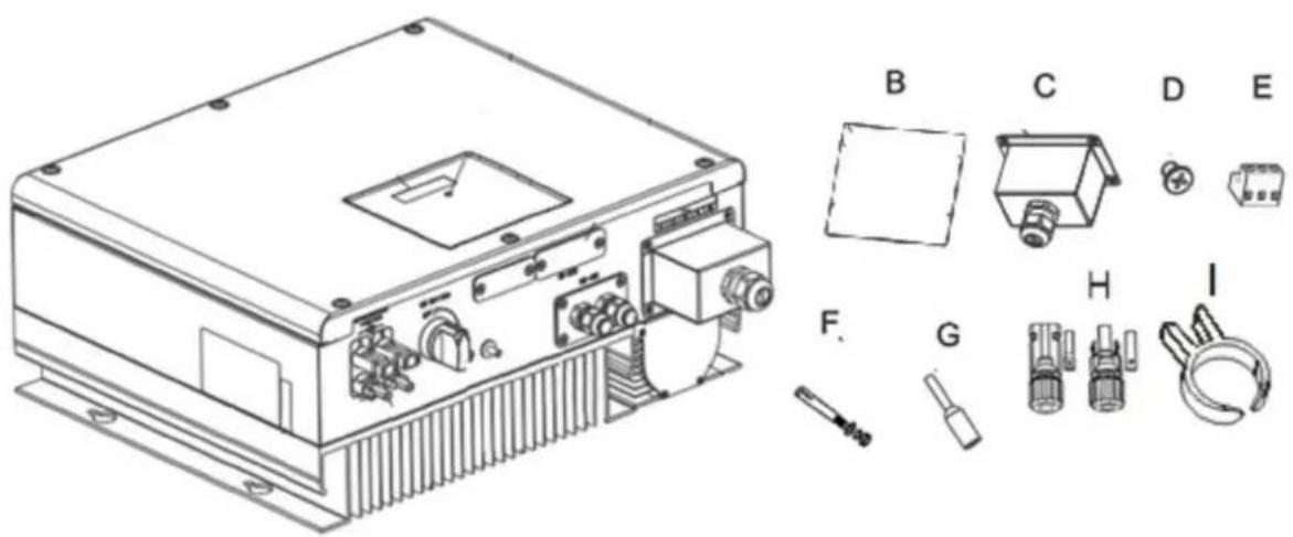
Fig4.1
| Item | quantity | Descripon |
| A | 1pcs | CPS Mini Central inverter |
| B | 1pcs | Quick installaon guide |
| C | 3set | Cable gland for AC Connecon |
| D | 4set | M4 Cross recessed countersunk head screws |
| E | 1set | RS485 terminals |
| F | 4pcs | Explosion screw |
| G | 5pcs | Cord End Terminal |
| H | 3pcs | Field Wiring DC connectors -Amphenol H4 |
| I | 1pcs | DC Connector Removal Tool |
| J | 1pcs | Warranty Card(not show in the picture) |
| K | 1pcs | User manual (not show in the picture) |

Information
Though the packaging box of CPS Mini Central inverter is durable, please treat the packing box gently and avoid dispose the packing box.
5. Installaon
5.1 Safety instrucon
 | Danger to life due to re or explosion➢ Despite careful construction, electrical devices can cause res.➢ Do not install the inverter on easily ammable materials and where ammable materials are stored. |
 | Risk of burns due to hot enclosure partsMount the inverter in such a way that it cannot be touched unintenonally. |
All electrical installaons shall be done in accordance with the local and naonal electrical codes. Do not remove the casing. Inverter contains no user serviceable parts. Request servicing to qualified service personnel. All wiring and electrical installaon should be conducted by a qualified service personnel.
Carefully remove the unit from its package and inspect for external damage. If you nd any abnormal, please contact your local dealer.
Be sure the inverters connected with the protecon earth grounding in order to protect personal safety from electrical shock.
The inverter can only be operated with PV generator. Do not connect any other energy source to it.
Both AC and DC voltage sources are terminated inside the PV Inverter. Please disconnect these circuits from its power source before servicing.
This unit is designed to feed power to the public power grid (ulity) only. Do not connect this unit to an AC source or generator. Connecng Inverter to external devices could result in serious damage to your equipment.
When solar panel exposed to light, it generates a DC voltage and will charge the DC link capacitors inside inverter. Thus, energy stored in the DC link capacitors presents a risk of electric shock even aer the unit is disconnected from the grid and photovoltaic panels. Do not remove the casing until at least 5 minutes aer disconnecting all power sources.
Although designed to meet all safety requirements, some parts and surfaces of Inverter are sill hot during operaon. To reduce the risk of injury, do not touch the heat sink at the back of the PV-Inverter or nearby surfaces while Inverter is operang.
5.2 Selecng the Installaon Locaon
This is guidance for installer to choose a suitable installaon locaon, to avoid damage to device and operators,
The wall selected to install the inverter must be strong and rm enough to support and bear the weight of the inverter for a long period me. (Refer to Chapter 3.2)
The locaon selected must be suitable for inverters' dimension. (Refer to 3.2 Dimensions and Fig.5.2 Required Clearances)
Do not install the inverter on structures constructed of ammable materials.
➢ Never install the inverter in environment without air ow. nor dust environment.
The Ingress Protecon rate is IP65 which means the inverter can be installed outdoors and indoors.
Do not expose the inverter to direct sunlight to avoid the power and eciency derating caused by excessive heang.
The humidity of the installaon locaon should be 5\~95% without condensaon.
The ambient temperature applied on the inverter should be -25°C +60°C .
The installaon locaon must be freely and safely to make service possible all the me.
The inverter can be installed with vercally, backward lted and horizontally.
Never install with upset-down and forward lted.(Refer to drawings below).
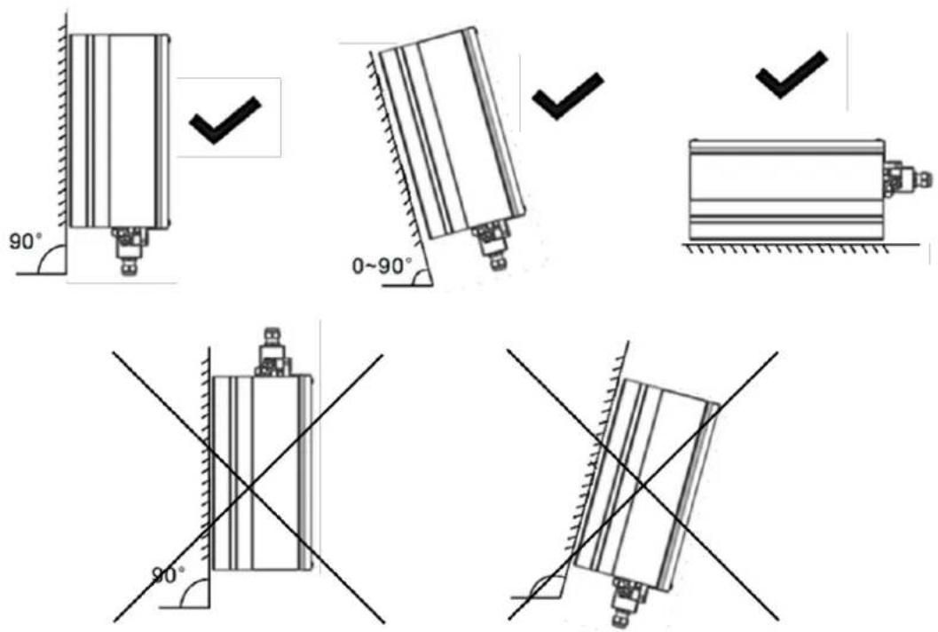
Fig5.1
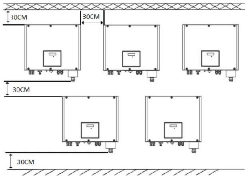
Noce when more than one inverters be installed, the minimum clearances between inverters should be large than 300mm to assure cooling works well. (Refer Fig.5.2 Required Clearances).

Fig5.2
Do not install the inverter near television antenna or any other antennas and antenna cables.
Do not install the inverter in living area, noise might affect daily life.
For security reasons, don't install the inverter in place where the children can reach.
5.3 Installaon guide
Step 1 : Mounng Expansion Bolt

DANGER In order to avoid electrical shock or other injury, make sure there is no electrical conduit buried in the wall before drilling holes.
To mount the inverter on the wall, we should mount expansion bolt to the wall rmly rst.
Drill 4 holes for expansion bolt use the Fix Hole Paper as template.
Fix the mounng expansion bolt on the wall as the gures shown below, combine four expansion bolt with four M6 nuts. Refer to Fig 5.3.

Fig5.3
Step2 : Mounng Inverter

WARNING
Always checking moung expansion bolt is really rmly and solid mounted on the wall. Falling equipment can cause fatal injury.
Aer the bracket is rmly mounted on the wall, then mount the inverter on the bracket.
Rise up the inverter a little higher than expansion bolt. Considering the weight of inverter, you need to hang on the inverter. During the process please maintain the balance of the CPSPVXXXXETL-S
➢ Hang the inverter on the expansion bolt
Aer conrming the inverter is stuck on expansion bolt, fasten four M6 screws. Refer to Fig 5.4.
➢ Connecon of a second protective earthing conductor. Please reference in Fig5.5.
Recommend awning installaon, the purpose is to extend the inverter service life and reduce the power derang of the inverter. The dimension of the awning refer to Fig 5.7.

Fig 5.4.

Fig 5.5.
Step 3 : Installaon layout

Information
Avoid exposing inverter to direct sunlight, rain or snow to extend the inverter service life despite the IP65 protecon degree. Exposure to the sunlight may cause additional internal heang which will cause power derang.
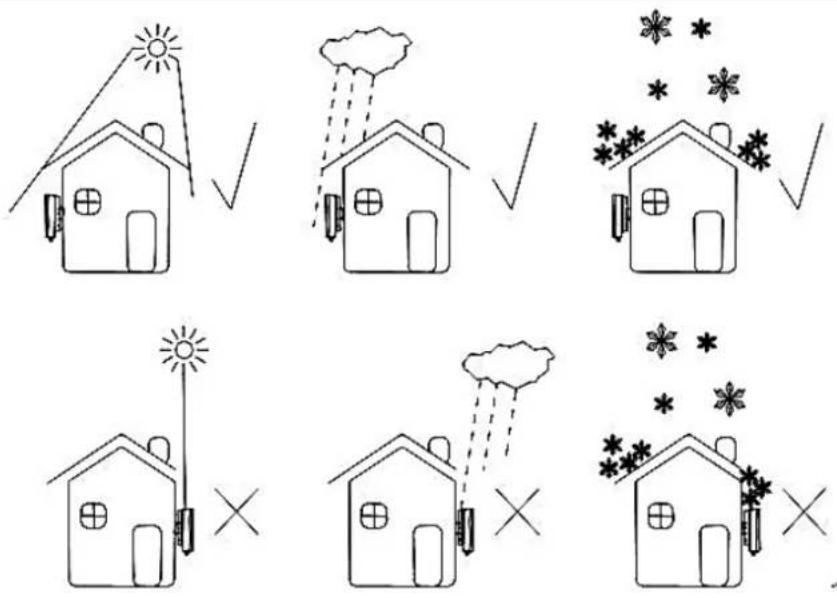
Fig5.6

Fig5.7
6. Electric conncon
6.1 AC Connecon.
| [DYD3W] | DANGER | Danger to life due to hazards voltages!High voltages which may cause electric shocks are present in the conducive parts of the inverter. Prior to performing any work on the inverter, disconnect the inverter from the AC and DC sides |
 | WARNING | Danger of damage to electronic components due to electrostac discharge.Take appropriate ESD precautions when replacing and installing the inverter. |
Condions for the AC Connecon
You must comply with the conncon requirements of your utility operator.
All usages must comply with the regulaons.
Residual-current protective device
The On-grid Solar Power Generang System is equipped with an integrated universal residual-current monitoring unit.
If the network operator spulates a residual-current protecve device, you must use a residual-current protecve device that triggers in the event of a residual-current of 100 mA or more.
Connecon of a second protective conductor
In some installaon countries, a second protective conductor is required to prevent a touch current in the event of a malfuncon in the original protective conductor.
For installaon countries falling within the scope of validity of the IEC standard 62109, you must install the protecve conductor on the AC terminal with a conductor cross-secon of at least 10mm2Cu .
Or install a second protecve conductor on the earth terminal with the same cross-secon as the original protecve conductor on the AC terminal.
Load disconnecon unit
You must install a separate three-phase miniature circuit-breaker or other load disconncon unit for each On-grid Solar Power Generating System in order to ensure that the On-grid Solar Power Generang System can be safely disconnected under load.
Measure the public grid voltage and frequency (Voltage: 400Vac; Frequency: 50Hz/60Hz; in 3-Phase);
Open the breaker between the On-grid Solar Power Generang System and utility;
Specicaon of AC breaker: CPSPV70000ETL-S: 16A/400V
CPSPV8000ETL-S:20A/400V
CPSPV9000ETL-S: 20A/400V
CPSPV10000ETL-S: 25A/400V
CPSPV11000ETL-S: 25A/400V
CPSPV12000ETL-S: 30A/400V
CPSPV15000ETL-S: 35A/400V
AC Power Cable requirements:
| Model | Diameter(mm) | Area( mm2 ) | Available wire gauge (AWG) |
| CPSPV7000ETL-S | 2.05~4.11 | 4~16 | 12~6 |
| CPSPV8000ETL-S | 2.05~4.11 | 4~16 | 12~6 |
| CPSPV9000ETL-S | 2.05~4.11 | 4~16 | 12~6 |
| CPSPV10000ETL-S | 2.05~4.11 | 4~16 | 12~6 |
| CPSPV11000ETL-S | 2.05~4.11 | 4~16 | 12~6 |
| CPSPV12000ETL-S | 2.05~4.11 | 4~16 | 12~6 |
| CPSPV15000ETL-S | 2.05~4.11 | 4~16 | 12~6 |

NOTICE
Please do not use single-core wire cable.
There are three types of AC connector for CPS Mini Central series On-grid Solar Power Generang System. Please follow the instrucons corresponding to the parts we oer you.
AC terminal :
1 The AC side terminals of the On-grid Solar Power Generang System are like the following gure, it is clear to conrm that 'L1, L2, L3' represents three live line output, 'N' represents neutral line and grounding line.
2 Connect ve standard cables into relevant terminals. The ve cables should be put through the protecon shell, as gure below.
3 Fasten the protecon shell onto the boom of the On-grid Solar Power Generang System, make sure the four screws are ghtened, the completed appearance is like the below gure.
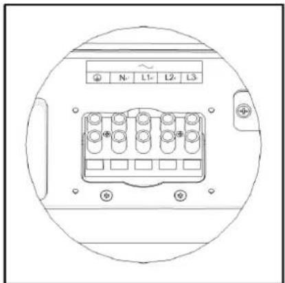


Fig6.1
6.2 DC conncon
 | DANGER | Danger to life due to hazards voltages!Before connecng the PV array, ensure that the DC switch and AC breaker are disconnect from the inverter. NEVER connect or disconnect the DC connectors under load. |
 | WARNING | Improper operaon during the wiring process can cause fatal injury to operator or unrecoverable damage to the inverter. Only qualified personnel can perform the wiring work. |
 | WARNING | Risk of damage to the inverter.If the voltage of the PV modules exceeds the maximum input voltage, 1,000Vdc, of the inverter, it can be destroyed by the overvoltage. This will void all warranty claims.Do not connect strings to the inverter that have an open-circuit voltage greater than the maximum input voltage of the inverter. |
 | WARNING | To reduce the risk of electric shock, avoid touching the live components and treat the terminals carefully. |
 | Information | The PV modules should have an IEC61730 Class A rang*.Please use the same brand male and female PV connectors.Under any conditions the total circuit current should never exceed the Max. Current. |
*Relate only to transformerless installaon
➢ Check the assembled DC connectors for correct polarity and connect them to the inverter.
➢ Check the conncon cables of the PV modules for correct polarity and make sure that the maximum open circuit voltage of each string should never exceed 1000V.
In order to optimize the system conguraon, the two inputs are recommended to be connected to the same number of PV modules.
The maximum short circuit current of each PV string is no more than 12A under any conditions.
In order to secure the inverter from water and dust, all unused DC inputs must be closed with sealing plugs.
The diagram drawing of DC side is shown as below, Fig 6.2, noce that the connectors are in paired (male and female connectors). The vendor of DC connectors for both PV arrays and inverters should be H4 (Amphenol) or equivalent.
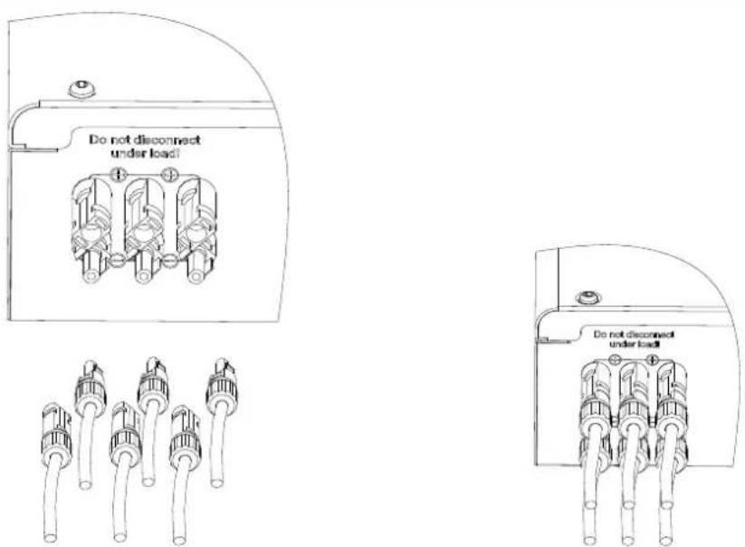
Fig 6.2
6.3 Grounding
AC Grounding
The CPS Mini Central On-grid Solar Power Generang System must be connected to the AC grounding conductor of the power distribuon grid via the ground terminal (PE).
PV Grounding
The grounding conductor in the framework of the PV array must be connected to the PV grounding conductor and the DC grounding conductor. The cross-secon of the grounding conductor corresponds to the cross-secon of the largest conductor in the DC system.
DC Grounding Conductor
A DC grounding conductor may be required by the Authority Having Jurisdicon (AHJ). Use the terminal block for the PV grounding conductor and DC grounding conductor.
Ground kit
If PV modules of the PV system require POSITIVE or NEGATIVE to connect to GROUND, the output of On-grid Solar Power Generang System should connect to grid with an isolang transformer.
The conneccon method is below:

N of transformer should not be connected to PE.
6.4 Grid Type
Common grid type
Based on the local GRID standards, it may select dierent conncon types. In the following you will find an overview of the most common type of grid structure.


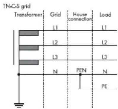


7. Start-Up and Shut down the inverter

WARNING
Make sure the inverter has connected DC and AC conductor cables correctly according to the wiring diagram of secon 6.1 & 6.2.
Always make sure the maximum open circuit voltage (Voc) of each PV string is less than 1000VDC.
7.1 Start-Up the inverter
Turn on the DC switch of the inverter, and the inverter will start automacally when the input voltage is higher than 200V.
The LCD display shown the information as below picture in the initialized stage:
![graph TD A["CyperPower PV Inverter"] --> B["SerNo: PR34200090"] B --> C["Model: PVBC00F161"] C --> D["FW Version: DH 1.0 - DH 0.0"]](/content/2026/05/997765/images/33e301157927abb2ad4aa30e4763c39872a23461909f3532f12823c1264ba01a.jpg)
Fig 7.1
The display following shown the informaon below and the LED will turn to red without utility:
No AC Connection
Fig 7.2
In order to connect to AC grid you must turn on AC disconnect
The LCD text line's informaon display as below:
Connect in : 30s
Fig 7.2
When mer counts to 0s, the inverter aempts to connect to the grid. Once it outputs power to the grid successfully, LCD shown as below picture and LED turn to green.
![graph TD A["Connect in: s"] --> B["Connect OK"]](/content/2026/05/997765/images/f8480a7300dee181d83542ffb2966dc099f032ef72ef6a19678455836c37a08c.jpg)
Fig 7.3
It means the CPS Mini Central inverters successfully start up!
7.2 Shut down the Inverter
Turn o the DC switch of the inverter.
The LCD text line's informaon display as below:
PV Power Low
Fig 7.4
The LED will turn to red
In this state, it is working in standby mode, isolated from the DC power
Fully shut down the inverter by turning o the AC grid unl the LCD and the LED are powered o.
8. Commissioning
8.1 Check before commissioning
➢ Conrm the inverter is rmly installed again.
➢ Install locaon is suitable for operaon and maintenance.
Good air ow condion.
The inverter is connected properly with its accessories.
Cables are well protected from mechanical damage.
Suitable sizing of AC circuit breaker.
8.2 Commission the Inverter.
Remove all covers from the PV array.
▶ Check the PV and AC voltage.
➢ Turn the DC Disconnect to posion "ON".
If the inverter connected with PV arrays the input voltage is higher than 200Vdc without utility, LCD will display messages in order as below:
![graph TD A["CyperPower PV Inverter"] --> B["SerNo: PR34200090"] B --> C["Model: PVBC00F161"] C --> D["FW Version: DH 1.0 - DH 0.0"]](/content/2026/05/997765/images/c8ce53e526b87ff0de6228d1fcfbb0a156353c0eb7a0029e518fae8654f531d3.jpg)
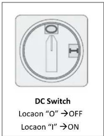
Fig 8.1
➢ Turn on the AC breaker between inverter and grid, the system will operate automacally.
Under normal operang condions, the LED turns green.
➢ Check me and date of inverter correct or not.
Single knock to light the backlight → Inverter info (single knock) → System Time, if they are not correct, please set them(Refer to Secon 9.4 about seng me and date)
Finish commissioning.
8.3 Operaon Modes
Normal Mode
In this mode, the inverter works normally and LED turns green.
- Whenever the DC voltage is higher than 200Vdc also the PV array supply enough power, the inverter converts power to grid as generated by the PV panels.
- When inverter is in its rst startup also the DC voltage is higher than 160Vdc and lower than 200Vdc, the inverter will work in standby mode and aempt to connect the grid unl the DC voltage is higher than 200V again. In standby mode the inverter consumes power from PV panel to monitor the internal system.
- Whenever the DC voltage is higher than 200Vdc also the PV array supply enough power, the inverter converts power to grid as generated by the PV panels. - When inverter is in its rst startup also the DC voltage is higher than 160Vdc and lower than 200Vdc, the inverter will work in standby mode and aempt to connect the grid until the DC voltage is higher than 200V again. In standby mode the inverter consumes power from PV panel to monitor the internal system.
Fault Mode
The internal intelligent controller can connuously monitor and adjust the system state. If inverter nds any unexpected conditions such as system fault and inverter fault, the fault informaon will be displayed on the LCD. In fault mode the LED turns red.
Derang mode
Derang of the inverter is a method to avoid overload or overheat from inverter to be damaged by reduce the power generaon. The derang may be caused by the following reasons:
- Ambient temperature makes temperature of inverter too high.
- Input over voltage
• Output under voltage - External acve power control instrucon applied.
9. Display seng
LCD screen provide informaon about the working state of the inverter. To operate with the display, one require to knock near the "KNOCK" Icon by hand or tools
9.1 LED display
The LED represents the status of the inverter.

Fig 9.1
| LED color /status | Inverter status |
| Green/constant | Operaon |
| Green/ashing | countdown for 30s ,standby mode |
| Red/constant | ➢ Fault- contact installer➢ Standby module |
| Red/ashing | ➢ Soware update |
9.2 Inverter informaon.
Aer power on for several seconds by either DC power or AC power, the LCD will display basic informaon of inverter.
Aer displaying the four info for 2 seconds without further manual operaon, the background light will turn itself o.

Fig 9.3
9.3 Display Operaon
◆ Knock type and denion
The inverter can support four kinds of knock: single knock, double knock, thrice knock, four knock. Each kind of knock has dierent funcon. The Text line can be used for seng language, models, communicaon address, string informaon, me and Date. Before start to set relave parameter, you have to input the seng password.
Single knock for "Next"
Double knock for "Enter"
Thrice knock
Under seng mode - "Conrm and Exit"
Four knock – "Exit seng page and go back home page."
◆ Overall display interface introducon
Single Knock on the enclosure and the text line shown informaon about of the CPS Mini CPSXX000ETL-S:
![graph TD A["CyberPower PV Inverter"] --> B["SetNo: PR34200090"] B --> C["Model: PVBC00F161"] C --> D["FW Version: DH 1.0 - DH 0.0"] D --> E["Connect in: s"] E --> F["Connect OK"] F --> G["AC VA/Wate: VA W"] G --> H["Etoday: 50.2 Kwh"] H --> I["Eall: 2000 Kwh"] J["Setting"] --> K["Double Input Word:1…](/content/2026/05/997765/images/1812c6477999f6bcb98828a8ea58fcb76a7d208fdd199f421a3bab43ad694799.jpg)
Fig9.4
◆ Input seng password
Single knock on the enclosure lid single unl the text line shown "seng ...". Refer to Fig 9.7. Then double knock to enter the seng page, the inverter requests password shown as Fig 9.8.
Double knock on the enclosure to start edit the number text "000". 1 st number will start to blink. Follow with more single knock will increase the 1 st number from "000" to "100". The 1 st number will add 1 with more single knock, the range of number text is 0\~9. Then double knock to enter the value at 1 st number and same operaon performed on the remaining 2 number.
Once you complete the number to ll these numbers, thrice knock should be provided as nal conrmaon and exist. One can set the language, COM address and me/Date in the same way.
Setting
Fig 9.9
Input Word:123 000
Fig 9.10
◆ Seng language
Single knock on the enclosure until the text line cycles shown "Set language". Refer to Fig 9.9. Double knock to start to edit the Language shown as Fig 9.10.
You can choose the language by single knocking; the language includes English, Dutch, Spanish, French, and Italian. Thrice knock to conrm the language you have chosen shown as Fig 9.11. Forth knock to quit the seng menu.
Set Language
Fig 9.11
Set Language English
Fig 9.12
Set Language XXXX
Set OK
Fig 9.13
◆ Seng RS485 com address
Single knock on the enclosure until the text line cycles show "Com Address". Refer to Fig 9.12.
Double knock the enclosure to start edit the low digits in number text "001". You can to change it with more single knock on the enclosure shown as Fig 9.13.
If you want to set the address with higher digits, double knock to let the higher number text "020" ashing shown as Fig 9.14. Usually, the inverter COM address is within 0-32. Thrice knock to conrm the com address you have chosen shown as Fig 9.15. Forth knock to quit the seng menu.
Set Com Address 001
Fig 9.14
Set Com Address 001
Fig 9.15
Set Com Address 002
Fig 9.16
Set Com Address 112
Set OK
Fig 9.17
◆ Seng date and me
Single knock on the enclosure until the text line cycles to the me refer to Fig 9.16.
Double knock to start edit the year "2012", and the two lower number "12" will ash, then single knock to change it. Refer Fig 9.17.
Double knock to edit the month "01", and it will ash, then single knock to change it. Repeat same to day and the me sengs. Thrice knock to conrm the date and me you have chosen shown as Fig 9.18. Forth knock to quit the seng menu.
Set Date/Time
Fig 9.18
Date: 2012/04/05
Time: 14:20:38
Fig9.19
Date: 2013/04/05
Time: 14:20:38
Fig9.20
Date: 2013/05/06
Time: 15:21:38
Set OK
Fig9.21
10. Communicaon
10.1 Using 'Solar Power Setup_3P' to Update rmware & monitor inverter
About the soware -Solar Power Setup_3P, please download from CyberPower ocial website. For more detail informaon about rmware upgrade, please refer to service manual or contact with CyberPower System, Inc.
The connecng diagram as follow:
![graph TD A["Device"] --> B["RS232 cable"] B --> C["Computer"] A --> D["USB-RS232 cable\nUsb-RS 485 cable"] D --> C](/content/2026/05/997765/images/b205fc7c531cdf8fe05abc8d80901b339372ace6c6eb50b16f374826831c1560.jpg)
Fig10.1

Information
If you want to update rmware online, please disconnect AC breaker of the inverter rst.
10.2 Monitor the inverters
The inverter provides RS232/RS485 interface to communicate with remote PC or logger. User can monitor the inverter state via the following types of communicaon systems. For more detail informaon, please contact with CyberPower Systems, Inc.
Monitor the inverters through RS485 interface with soware "Solar Power Monitoring".
![graph LR A["..."] --> B["Module 1"] A --> C["Module 2"] A --> D["Module 3"] A --> E["Module 4"] A --> F["Module 5"] B --> G["RS485"] C --> G D --> G E --> G F --> G G --> H["RS485/RS232"] G --> I["RS485/USB"]](/content/2026/05/997765/images/95d7f048cc4ca06e08ea632896c9bcc2f6172a62ddcc2010caa9facd27a98406.jpg)
Fig 10.2
Monitor the inverters through RS485 interface with "CPS Data Logger" for cloud applicaon.
![graph LR A["..."] --> B["Module 1"] A --> C["Module 2"] A --> D["Module 3"] A --> E["Module 4"] B --> F["RS485"] C --> F D --> F E --> F](/content/2026/05/997765/images/eae2314207b4ee56dcaf408c51220458344584ed6bab8e2aa7f5724a1d329c04.jpg)
Fig 10.3
10.3 RS485 cable conneccon
RS485 cable conncon
| Pin 1 → TR-(B) |  |
| Pin 2 → Shielding layer or no conncon | |
| Pin 3 →TR+(A) |
Denions of RS485 PLUG (standard) as follows:
| Pin 1 → TR-(B) |  |
| Pin 2 → Shielding layer or no conncon | |
| Pin 3 →TR+(A) |
Step 1: Please loosen four screws, take down the RS485 waterproof cover from inverter. If you don't choose RS485 as communicaon method, keep it on the inverter.

Fig 10.6
Step 2: Slightly loosen the swivel nut, remove theller-plug from the M16 cable gland.

Fig 10.6
Step 3 : Make the cable through the hole of cable gland and put the cable into the Rs485 terminals, x all cables with screwdriver ('1'to' T/R-(B)', '3'to' T/R+(A)', '2' to the shielding layer or no conncon). The type of cable is recommended as STP, FTP, AST
Step 4 : Plug in two terminals. Cover the x board.

Fig 10.7
Step 5 : Tighten 4pcs screws and cable gland.
11. Trouble shoong
Our quality control program assures that every inverter is manufactured to accurate speciaons and is thoroughly tested before leaving our factory. If you have diculty in the operaon of your inverter, please read through the following informaon to correct the problem.
| Warning code | Meanings | Suggeson |
| Warning 103 | Reading EEPROM fail | Restart inverter, if problem sll exist, Contact CyberPower. |
| Warning 104 | DSP and COM rmware version unmatch | Contact CyberPower. |
| Warning 105 | Wring EEPROM fail | Restart inverter, if problem sll exist, Contact CyberPower. |
| Warning 108 | PV is short | Contact CyberPower. |
| Warning 109 | BOOST drive abnormal | Contact CyberPower. |
| Error code | Meanings | Suggeson |
| Error 101 | Internal communicaon with host failed | Contact CyberPower. |
| Error 107 | Voltage circuit fail | Contact CyberPower. |
| Error 117 | Inverter relay fault | Contact CyberPower. |
| Error 119 | Residual current sensor error or circuit failure | Contact CyberPower. |
| Error 120 | Output current unbalance | Contact CyberPower. |
| Error 121 | Internal communicaon with slave failed | Contact CyberPower. |
| Error 122 | Internal bus over/under voltage | Contact CyberPower. |
| Error 124 | No AC Connecon | The grid is not connected to the Inverter .Please check the grid conncon |
| Error 125 | PV Isolaon Low | PV Insulaon value is outrange. Please check the PV Cable |
| Error 126 | Residual I High | Residual current is above limit . Please check the PV and AC Cable. Restart inverter, if problem sll exist, Contact CyberPower. |
| Error 127 | Output high DCI | Contact CyberPower. |
| Error 128 | PV Voltage High | PV input voltage is above 1000V . Please check the solar panel conguraon and wiring |
| Error 129 | AC V Outrange | The grid voltage is outrange . Please check the grid voltage by the LCD |
| Error 130 | AC F Outrange | The grid frequency is outrange. Please check the grid voltage by the LCD |
| Error 131 | Temperature over limit | Restart inverter, if problem sll exist, Contact CyberPower. |
12. Cercates
CPS Mini Central series inverters are designed to use worldwide, hence the inverters meet dierent safety standards of variety countries and regions.
| Model | Cercates |
| CPSPV7000ETL-S | IEC 62109-1&-2, VDE0126-1-1, EN50438, VFR 2014, CE |
| CPSPV8000ETL-S | IEC 62109-1&-2, VDE0126-1-1, EN50438, VFR 2014, CE |
| CPSPV9000ETL-S | IEC 62109-1&-2, VDE0126-1-1, EN50438, VFR 2014, CE |
| CPSPV10000ETL-S | IEC 62109-1&-2, VDE0126-1-1, EN50438, VFR 2014, CE |
| CPSPV11000ETL-S | IEC 62109-1&-2, VDE0126-1-1, EN50438, VFR 2014, CE |
| CPSPV12000ETL-S | IEC 62109-1&-2, VDE0126-1-1, EN50438, VFR 2014, CE |
| CPSPV15000ETL-S | IEC 62109-1&-2, VDE0126-1-1, EN50438, VFR 2014, CE |
13. Contact
If you have technical problems concerning our products, contact your installer or CyberPower. During inquiring, please provide below informaon:
- Inverter type
- Modules informaon
- Communicaon method
- Serial number of Inverters
- Error code of Inverters
- Display of inverter
CyberPower Systems, Inc.
11F., No.26, Jinzhuang Rd., Neihu Dist., Taipei City 11469, Taiwan (R.O.C.)
Serviceline
- CONTENTS
- INFORMATION ON THIS MANUAL....3
- SAFETY 5
- PRODUCT DESCRIPTION 9
- UNPACKING 17
- INSTALLATION 18
- ELECTRIC CONNECTION 24
- START-UP AND SHUT DOWN THE INVERTER....29
- COMMISSIONING 31
- DISPLAY SETTING 33
- INFORMAON ON THIS MANUAL
- 1.1 VALIDITY
- 1.2 TARGET GROUND
- 1.3 SYMBOLS USED
- SAFETY
- 2.1 INTENDED USE
- 2.2 SAFETY PRECAUONS
- 2.3 ASSEMBLY WARNINGS
- 2.4 ELECTRICAL CONNECON WARNINGS
- 2.5 OPERAON WARNINGS
- 2.6 SYMBOLS ON THE INVERTER
- PRODUCT DESCRIPON
- 3.1 CPS MINI CENTRAL SERIES OVERVIEW
- PRONT PANEL (ITEM A): LCD & LED
- 3.2 SIZE AND WEIGHT
- 3.3 TYPE LABEL
- 3.5 TRANSPORTAON
- 3.6 STORAGE OF INVERTER
- 3.7 THE ADVANTAGE OF THE CPS MINI CENTRAL INVERTERS
- UNPACKING
- INFORMATION
- INSTALLAON
- 5.1 SAFETY INSTRUCON
- 5.2 SELECNG THE INSTALLAON LOCAON
- 5.3 INSTALLAON GUIDE
- STEP 1 : MOUNNG EXPANSION BOLT
- DANGER IN ORDER TO AVOID ELECTRICAL SHOCK OR OTHER INJURY, MAKE SURE THERE IS NO ELECTRICAL CONDUIT BURIED IN THE WALL BEFORE DRILLING HOLES
- STEP2 : MOUNNG INVERTER
- WARNING
- STEP 3 : INSTALLAON LAYOUT
- ELECTRIC CONNCON
- 6.1 AC CONNECON
- CONDIONS FOR THE AC CONNECON
- RESIDUAL-CURRENT PROTECTIVE DEVICE
- CONNECON OF A SECOND PROTECTIVE CONDUCTOR
- LOAD DISCONNECON UNIT
- NOTICE
- PLEASE DO NOT USE SINGLE-CORE WIRE CABLE
- AC TERMINAL
- 6.2 DC CONNCON
- 6.3 GROUNDING
- AC GROUNDING
- PV GROUNDING
- DC GROUNDING CONDUCTOR
- GROUND KIT
- 6.4 GRID TYPE
- COMMON GRID TYPE
- START-UP AND SHUT DOWN THE INVERTER
- 7.1 START-UP THE INVERTER
- 7.2 SHUT DOWN THE INVERTER
- COMMISSIONING
- 8.1 CHECK BEFORE COMMISSIONING
- 8.2 COMMISSION THE INVERTER
- 8.3 OPERAON MODES
- DISPLAY SENG
- 9.1 LED DISPLAY
- 9.2 INVERTER INFORMAON
- 9.3 DISPLAY OPERAON
- ◆ KNOCK TYPE AND DENION
- ◆ OVERALL DISPLAY INTERFACE INTRODUCON
- ◆ INPUT SENG PASSWORD
- ◆ SENG LANGUAGE
- ◆ SENG RS485 COM ADDRESS
- ◆ SENG DATE AND ME
- COMMUNICAON
- 10.1 USING 'SOLAR POWER SETUP_3P' TO UPDATE RMWARE & MONITOR INVERTER
- 10.2 MONITOR THE INVERTERS
- 10.3 RS485 CABLE CONNECCON
- TROUBLE SHOONG
- CERCATES
- CONTACT
- CYBERPOWER SYSTEMS, INC
- SERVICELINE
Brand : CyberPower
Model : CPSPV12000ETL-S
Category : Solar panel