TM-7117E - Monitor Posiflex - Free user manual and instructions
Find the device manual for free TM-7117E Posiflex in PDF.


| Product Type | Standalone POS Monitor |
| Model Number | TM-7117E |
| Display Panel | 17" TFT LCD |
| Resolution | 1280 x 1024 |
| Active Area | 377.920 (H) x 270.336 (V) mm |
| Pixel Pitch | 0.264 x 0.264 mm |
| Viewing Angle | 80/80/80/80 degrees (U/D/L/R) |
| Contrast Ratio | 500:1 |
| Response Time | 6 ms (Rise) / 2 ms (Fall) |
| Brightness | 300 cd/m² |
| Touch Technology (TM-7117E) | 5-wire Resistive or IR touch |
| Touch Interface | USB (type A to B cable) |
| Display Interface | VGA |
| Power Supply | 12V / 40W (external adapter) |
| Dimensions (W x D x H) | 385 x 286 x 401 mm |
| Weight (Net) | 6.82 kg |
| Tilt Adjustment Range | 15° to 70° |
| VESA Mount Compatible | Optional (WB-6000V-B kit) |
| Side Attachment Support | Optional (SD-466Z or KP-300W) |
| OSD Buttons | 4 buttons on right side (menu, ext, +, -) |
| Power LED Indicator | Solid blue (ON), solid green (standby), OFF |
| Included Accessories | VGA cable, USB A-B cable, power cord, adapter, user manual |
| Dual Touch Manager | Supported for extended mode (resistive/IR) |
| Compatible OS | Windows (with driver) |
Frequently Asked Questions - TM-7117E Posiflex
User questions about TM-7117E Posiflex
0 question about this device. Answer the ones you know or ask your own.
Ask a new question about this device
Download the instructions for your Monitor in PDF format for free! Find your manual TM-7117E - Posiflex and take your electronic device back in hand. On this page are published all the documents necessary for the use of your device. TM-7117E by Posiflex.
USER MANUAL TM-7117E Posiflex
natural_image
Black rectangular electronic display stand with a flat top and base (no visible text or symbols)√ 17" TM/LM-7117E
Standalone Monitor....(x 1)
√ VGA Cable....(x 1)
√ USB type A to B cable....(x 1)
√ Power Cord....(x 1)
√ 12V/40W Power Adapter.....(x 1)
√ User Manual....(x 1)
Product Features
● 17" TFT LCD panel
● LCD resolution up to 1280 x 1024
● 5-wire resistive or IR touch panel for TM-7117E
● Easy tilt angle adjustment from 15^ to 70^
- 2 x USB port support
- Optional side attachment support (SD-466Z or KP-300W)
● Optional VESA mounting kit (WB-6000V-B)
● Dimension : 401 mm (H) x 385 mm (W) x 286 mm (D);
- Weight: 6.82 kg
Views of the TM/LM-7117E
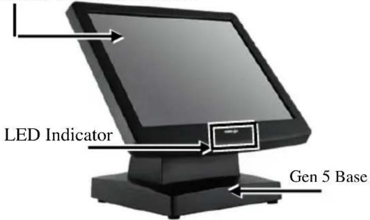
Front View
17" LM-7117E LCD Panel
17" TM-7117E Resistive or IR Touch Panel
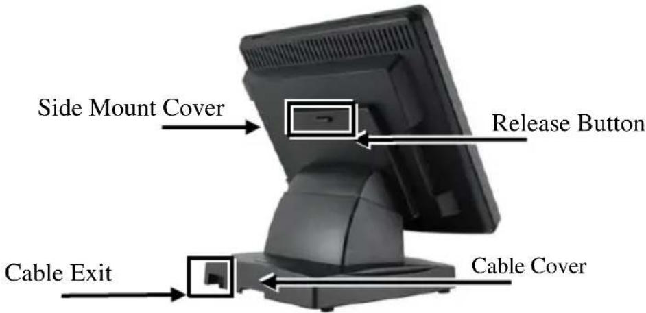
Rear View
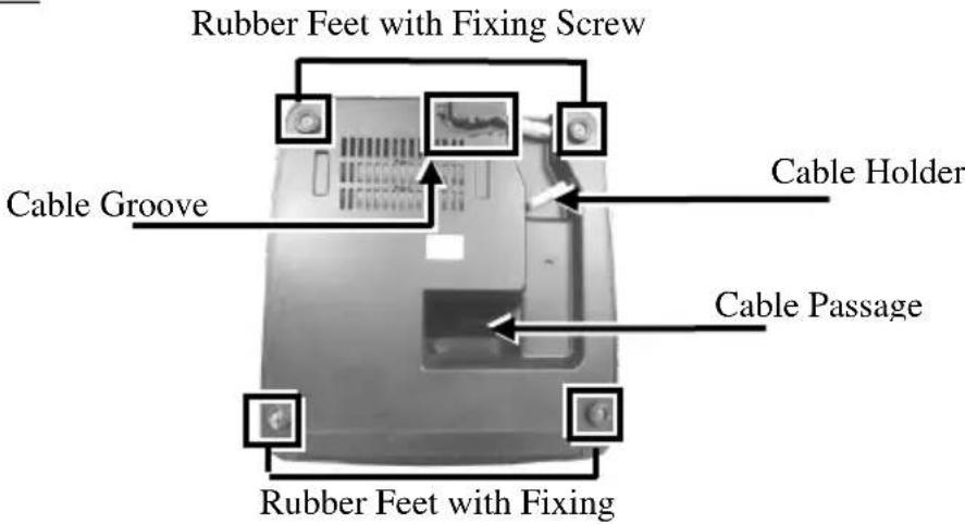
Bottom View
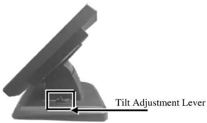
Left-Side View
Right-Side View
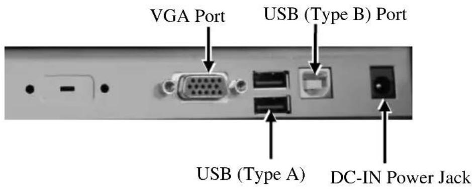
I/O Ports
Positioning your monitor for a Perfect Viewing Angle
Follow the below steps to adjust the viewing angle for TM/LM-7117E with Gen5 base stand using the tilt adjustment lever.
- After pushing down the tilt adjustment lever on the right side of the stand, tilt the screen up or back to your desired angle.
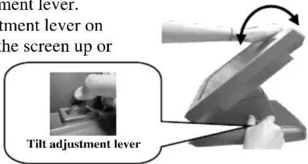
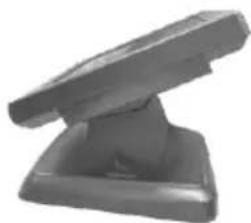
- Release the adjustment lever to lock the LCD panel into place.
natural_image
3D rendered image of a gray mechanical component with a flat top and base (no text or symbols visible)Connecting VGA and USB Cables
Gen5 base features its own cable management to help you well organize the cords. The following will provide some useful cable-routing instructions for you to connect VGA and USB cables to TM/LM-7117E.
- To release LCD panel from Gen5 base, support your monitor with one hand holding to the bottom of the panel and then push it up while pressing down the release button located on the back of TM/LM-7117E.
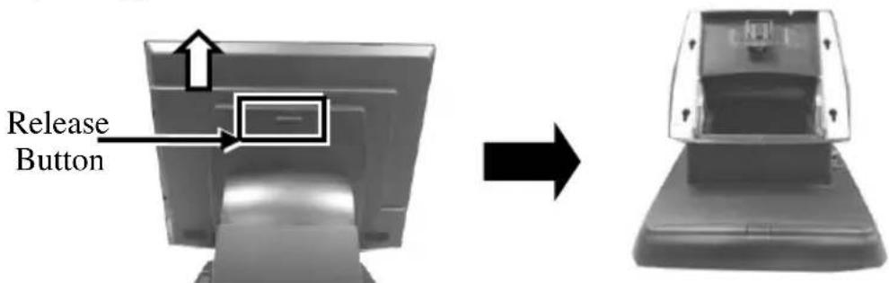
- Laying Gen5 base stand with its bottom facing towards you.
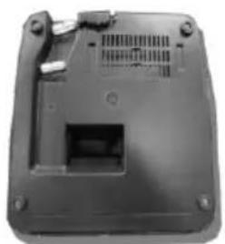
natural_image
Black plastic electronic device casing with ventilation slots and mounting feet (no visible text or symbols)- Take power adaptor, VGA and USB cables, and then neatly thread the cables along the cable groove first, and then snap it into the cable holder as shown in the figure.
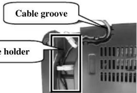
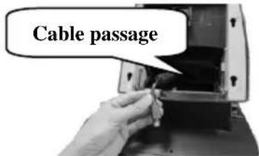
- Pass the cables through the cable passage.
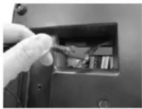
natural_image
Close-up of a hand inserting cables into an open electronic device (no visible text or symbols)- Place Gen5 base in upright position and make sure the cables can be pulled out of the cable passage.
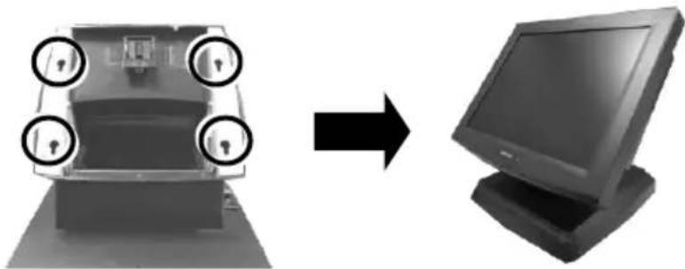
- Lift your monitor to aim four screw bolts on the rear of the monitor to the four screw holes on the Gen5 base. Then, along the rail slots push down the monitor until the LCD panel is well locked into place with a click sound.
natural_image
Diagram showing a device with four lock icons moving to a computer monitor (no text or symbols present)- Connect the monitor to the terminal using VGA cable.
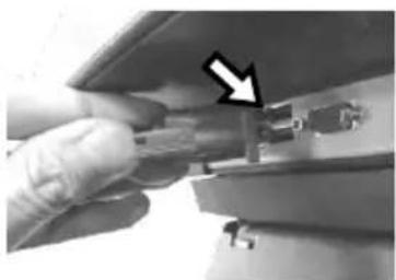
7.1 Connect one end of the VGA cable to the VGA port at the bottom I/O plate of your monitor.
natural_image
Close-up of a hand holding a small electronic component with an arrow pointing to it (no visible text or symbols)7.2 Take the other end of VGA cable to insert it into the VGA port of your terminal.
- For TM series or LM series with side attachment, please connect the monitor to the terminal using USB type A to B cable to enable touch function for your monitor.
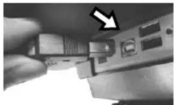
8.1 Grab Type-B connector of USB cable, and then insert it into Type-B USB port of your monitor
natural_image
Close-up of a hand holding an electronic device with a pointing arrow (no visible text or symbols)8.2 Properly attach Type-A connector of USB cable to your POS terminal.
- To use external sources to supply power to your monitor, plug power adapter to the DC-In power jack and then connect its power cord to electrical outlet.
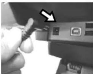
natural_image
Close-up of a hand inserting a USB into a device with a black arrow pointing to the next component (no visible text or symbols)Powering ON/OFF your Monitor
To start up TM/LM-7117E, you have to make sure that the monitor is well connected to POS terminals and electricity is supplied to the monitor through external power sources.
Power ON TM/LM -7117E
Press the power button of the terminal to power up the terminal. Few seconds later the monitor will be initiated automatically.
Power OFF TM/LM -7117E
After following the standard shutdown procedure to shut down your terminal, the monitor will be consequently turned off.
Power LED Indicator
Power LED indicator, located at the bottom of the screen, is used to notify users of the current status of your monitor by emitting various LED signals. Please refer to the below chart to accurately interpret the of the indicators status to facilitate your troubleshooting.
| Status | Description |
| ON, solid blue | System power ON |
| ON, solid green | System Standby |
| OFF | System power OFF |
Identifying your Monitor as Secondary Touchscreen Monitor in Extended Mode
Based on the type of your touch panels, you are required to adopt different approaches to set up TM series as the extended monitor when you attempt to extend the desktop across multiple monitors. In the following section the related descriptions will be offered to help you achieve the purpose.
For TM-7117E Model with Resistive or IR Touchscreen
For TM-7117E users, please follow the below instructions to complete installation of The Dual Touch Manager, a tool designed to allow your monitor to work as a secondary touchscreen monitor in extended mode.
- Make sure that the monitor is well connected to your POS terminal with USB type A to B cable.
- Visit Posiflex official site (http://www.posiflex.com/en-global/Home/index). Or, you may find USB Dual Touch Manager from your Posiflex POS terminal instead.
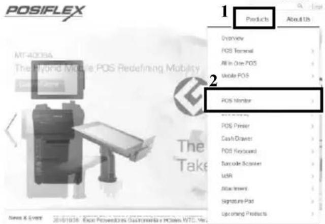
- Click on Products, which is located on the upper right side of your browser window. Then, select POS Monitor in the pop-up menu.
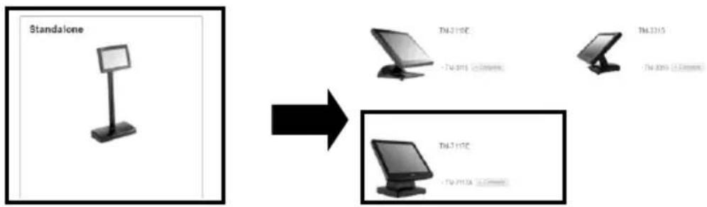
- Select Standalone type of POS monitor. After scrolling down the page, click on TM-7117E item.
flowchart
graph LR
    A["Standalone"] --> B["TC 1:15C - TC 2:015 (2.3mm/sec)"]
    A --> C["TC 2:15 - TC 3:015 (2.3mm/sec)"]
    A --> D["TC 3:15C - TC 4:15A (2.3mm/sec)"]
- Click on the Download tab, and then Drivers & Utility. Products
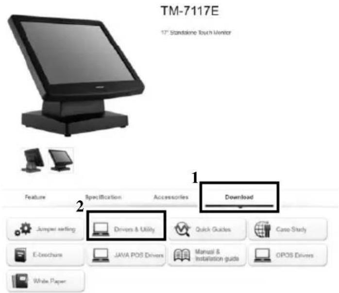
- Click Setup icon of USB Dual Touch Manager to install the USB Dual Touch Manager.
| Upload Date | Type | Description | Version | Size | Remark | Download |
| 2016/3/8 | Drivers & Utility | TM-8115X Series Resistance/IR USB Dual Touch Manager for Windows | v.3.03 | 3.3 MB |
- Follow the instructions to complete the manager installation. After the installation is finished, restart your terminal.
Setting up Display Resolution for Your Monitor
The below chart defines the list of recommended display settings for TM/LM-7117E. Improper display configuration will prevent the monitor from properly displaying the image and lead to a warning message of “out of range” prompted on the screen.
| Display Resolution | Horizontal Frequency (KHz) | Refresh Rate (Hz) |
| 640 x 400 | 31.5 | 70 |
| 640 x 480 | 31.5 | 60 |
| 37.9 | 72 | |
| 37.5 | 75 | |
| 720 x 400 | 31.5 | 70 |
| 800 x 600 | 35.1 | 56 |
| 37.9 | 60 | |
| 48.1 | 72 | |
| 46.9 | 75 | |
| 1024 x 768 | 48.4 | 60 |
| 56.5 | 70 | |
| 60 | 75 | |
| 1280 x 1024 | 64 | 60 |
| 80 | 75 |
Using the OSD Menu
OSD, as known as On-Screen Display, is employed to assist users in adjusting a variety of monitor-related settings depending on personal preference.
Through this section, it is expected to familiarize you with the options which are accessible via OSD menu, and to optimize your experiences with TM/LM -7117E.
Power & OSD Buttons
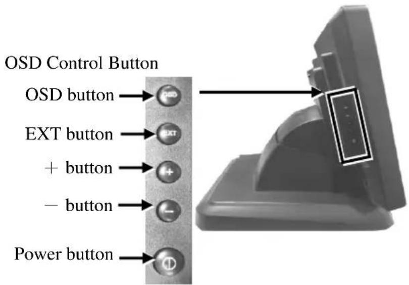
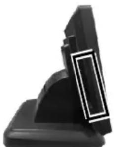
Power & OSD buttons are available on the right-hand side of the LCD monitor. Each of four OSD controls works differently in various occasions. Please refer to the below figure to get an idea of how they could possibly function in relation to OSD menu.
natural_image
Close-up of a black mechanical component with a white rectangular cutout (no text or symbols visible)| Icon | Description | |
 | OSD button | While OSD menu is activated:● to select the specific menu optionWhile OSD menu is deactivated:● to activate the OSD menu |
 | EXT button | While OSD menu is activated:● to exit from the current configuration |
 | “+” Button | While OSD menu is activated:● to navigate through OSD menu options● to increase the value of the specific item |
 | “-” Button | While OSD menu is activated:● to navigate through OSD menu options● to decrease the value of the specific itemWhile OSD menu is deactivated:● to initiate auto-adjustment function |
 | Power Button | ● turn on/off the monitor |
To help you get started with the OSD menu, the following points are guidelines you are suggested to go through:
- Firstly, press the OSD button to access the OSD menu.
- Scroll through OSD menu options using either the “+” or “-” button.
- Press the OSD button to select the particular menu option of interest. It will lead you to its sub-menu page if the selected menu option contains sub-menu items.
- Under the selected menu item with available sub-menu items, use the “+” or “−” button to switch among different items. Then, press the OSD button to select the sub-menu item which you intend to adjust.
- Use the “+” or “−” button to adjust the value of the selected OSD item. Then, press the OSD button to save settings.
- Press the EXT button to exit from the current configuration.
OSD Options
Please refer to the following table for further explanation of the accessible items.
| OSD Menu Options | Sub-menu items & Description |
| Picture | BacklightPress the “+” button to increase backlight intensity;Press the “-” button to decrease backlight intensity.BrightnessPress the “+” button to increase brightness;Press the “-” button to decrease brightness.ContrastPress the “+” button to increase contrast;Press the “-” button to decrease contrast.SharpnessPress the “+” button to increase sharpness;Press the “-” button to decrease sharpness. |
| Display | Auto AdjustmentExecute the auto-tune function for OSD menu, which will automatically perform fine tune of the image quality for optimizing screen performance.H PositionPress the “+” button to move the screen to the right;Press the “-” button to move the screen to the left.V PositionPress the “+” button to move the screen up;Press the “-” button to move the screen down.Pixel ClockUse the “+” or “-” button to adjust theClock setting for VGA input.PhaseUse the “+” or “-” button to adjust thePhase setting for VGA input. |
 Other Other | ResetRestore the current menu back to the default setting.Menu TimeSpecify the length of time for OSD menu to stay active on the screen.LanguageSpecify the language used in the OSD menu. |
 Information Information | Display information regarding display resolution, horizontal/vertical sync frequency, pixel clock (PCLK), etc. |
Specifications
| TM-7117E | LM-7117E | |
| Display | ||
| LCD Panel | 17" TFT LCD | |
| Resolution | 1280 (H) x 1024 (V) | |
| Active Area | 377.920 (H) x 270.336 (V) | |
| Pixel Pitch | 0.264(H) x 0.264 (V) | |
| Pixel Arrangement | RGB Vertical Stripe | |
| Viewing Angle | 80/80/80/80 degree (U/D/L/R) | |
| Contrast Ratio | 500 : 1 | |
| Response Time | 6 ms (Raising) / 2 ms (Falling) | |
| Brightness | 300 cd/m2 | |
| Touch | ||
| Touch type | 5-wire Resistive or IR | N/A |
| Interface | USB | N/A |
| General Specification | ||
| Display Interface | VGA | |
| Power Supply | 12V / 40W | |
| Dimension | 401 x 385 x 286 (W x D x H in mm) | |
| Weight | 6.82 (N.W. in kg) | |
※ The product information and specifications are subject to change without prior notice. To get the detailed information on TM/LM-7117E, please check this model from Posiflex Global Website
(http://www.posiflex.com/en-global/Download/download).
- Product Features
- Views of the TM/LM-7117E
- Front View
- Rear View
- Bottom View
- Left-Side View
- Right-Side View
- I/O Ports
- Positioning your monitor for a Perfect Viewing Angle
- Connecting VGA and USB Cables
- Powering ON/OFF your Monitor
- Power LED Indicator
- Identifying your Monitor as Secondary Touchscreen Monitor in Extended Mode
- For TM-7117E Model with Resistive or IR Touchscreen
- Setting up Display Resolution for Your Monitor
- Using the OSD Menu
- Power & OSD Buttons
- OSD Options
Brand : Posiflex
Model : TM-7117E
Category : Monitor