
Black Series BKT1050BN-A - Generator SteamSpa - Free user manual and instructions
Find the device manual for free Black Series BKT1050BN-A SteamSpa in PDF.


| Product Type | Steam Bath Generator, Model B-1050 (10.5 kW) |
| Brand | SteamSpa |
| Power Supply | 240 V AC, 50/60 Hz, Single Phase |
| Current Draw | 44 A |
| Recommended Wire Gauge | 6 AWG |
| Steam Output Pressure | 5 PSI |
| Steam Volume | 19 cu. in./min |
| Water Inlet Connection | 1/2" NPT, brass or copper pipe only |
| Steam Outlet Connection | 3/4" NPT, brass or copper pipe |
| Drain Connection | 1/2" NPT |
| Safety Valve Pressure Limit | 15 PSI |
| Control Panel | SS-BCT01BK, touchscreen with temperature display and Bluetooth/WiFi |
| Functions | Steam with adjustable temperature (10-43°C / 50-110°F) and time (5-60 min), LED light, chroma light, Bluetooth music, aroma pump, scheduled start, user presets |
| Connectivity | Bluetooth (for music), optional WiFi box for remote control via Smart Life app |
| Maintenance | Clean water sensor prongs every 6 months; replace inline water filter cartridge every 6 months; annual inspection of pipes and connections |
| Auto Drain | Automatic drain 30 minutes after steam stops, lasts 7 minutes |
| Safety Features | Pressure relief valve, hi-limit thermostat, ground fault protection, warning labels, requires licensed installation |
| Installation Requirements | Indoor use only; must be installed by licensed plumber and electrician; quick release system and pressure reducing valve required; water pressure must be 15-20 PSI |
| Warranty | Subject to registration within 90 days; void if not installed by licensed professional or if maintenance requirements are not met |
| Dimensions (approx.) | Not specified in manual; typical size for 10.5kW model: about 20" x 14" x 24" |
| Weight (approx.) | Not specified; estimated 50-70 lbs (23-32 kg) |
Frequently Asked Questions - Black Series BKT1050BN-A SteamSpa
User questions about Black Series BKT1050BN-A SteamSpa
0 question about this device. Answer the ones you know or ask your own.
Ask a new question about this device
Download the instructions for your Generator in PDF format for free! Find your manual Black Series BKT1050BN-A - SteamSpa and take your electronic device back in hand. On this page are published all the documents necessary for the use of your device. Black Series BKT1050BN-A by SteamSpa.
USER MANUAL Black Series BKT1050BN-A SteamSpa
Register your product within 90 days to ensure your steam bath generator is recognized as an official purchase and is eligible for warranty coverage.
Mail in the completed registry card (Pg. 2) or register online at www.SteamSpa.com/register
PRODUCT REGISTRATION\*
IMPORTANT: Your warranty will not be recognized unless this card is fully completed and returned or online registration is completed.
To ensure that your warranty is registered and confirmed please do one of the following:
- Register online at www.SteamSpa.com/register. You will be asked to fill out the same information you would in the registration card. Registering online is fast, secure and ensures we receive your information.
- Complete, cut-out and mail the registration card below. By returning this registration card we confirm the date of purchase for your new product. This confirmation will allow us to process any warranty claims.
Mail the card to: 5701 NW 35 Avenue, Miami, FL 33142

CUT ALONG DOTTED LINE.
Product Registration Card
Name ...... Address ......
Date of Purchase.... Order or Purchase #.... SKU or Model #....
Installer's Name Phone
I have read the Owner's Guide carefully and understand and agree that any installation, operation or maintenance of the steam generator and generator accessories must be done strictly in accordance with instructions and guidelines contained in the owner's manual and installation guide.
Signature Date
IMPORTANT WARRANTY INFORMATION!
The installation of a quick connect and release system is essential to the care and maintenance of your steam bath generator unit. Additionally, the use of an inline water filter with fresh cartridges prevents mineral deposit and built up from damaging the generator's internal plumbing and components.
Please be advised failure to comply with any of the following will VOID the warranty.
- The User must register product within 90 days of delivery. See www.SteamSpa.com/register.
- Installation must be performed by a licensed professional.
- A quick release & pressure reducing valve must be used for reliable periodic maintenance.
- An inline water filter must be installed to prevent mineral deposit and build up.
- Filter cartridge must be replaced no later than every 6 months.
Malfunctions, damages, parts replacement and labor resulting from improper installation, negligence, or lack of care and maintenance will NOT be covered under the SteamSpa Warranty.
For more information visit www.SteamSpa.com/warranty or call 1-800-856-0172.

READ ME FIRST!
IMPORTANT NOTE: As you follow these instructions, you will notice warning and caution symbols. This blocked information is important for the safe and efficient installation, operation and maintenance of this generator. These are types of potential hazards that may occur during this installation and operation:
WARNING states a hazard may cause serious injury or death if precautions are not followed.
CAUTION signals a situation where minor injury or product damage may occur if you do not follow instructions.
IMPORTANT NOTE: This highlights information that is especially relevant to a problem-free installation.
IMPORTANT SAFETY INSTRUCTIONS

WARNING
- Electrical grounding is required on all SteamSpa Generators.
- All electrical supplies should be disconnected when servicing generators.
- To reduce the risk of explosions,
- To reduce the risk of injury, children under the age of 16 should not use the steam bath.
- To reduce the risk of injury:
A. The wet suffaces of steam enclosures may be slippery. Use care when entering or leaving.
B. The steam head is hot. Do not touch the steam head and avoid the steam near the steam head.
C. Prolonged use of the steam system can raise excessively the internal human body temperature and impair the body's ability to regulate its internal temperature(hyperthermia). Limit your use of
steam to 10-15 minutes until you are certain of your baby's reaction.
D. Excessive temperatures have a high potential for causing fetal damage during the early months of pregnancy. Pregnancy or possibly pregnant women should consult a physician regarding correct exposure.
E. Obese persons and persons with a history of heart disease, low or high blood pressure, circulatory system problems, or diabetes should consult a physician before using a steam bath.
F. Persons using medication should consult a physician before using a steambath since some medication may induce drowsiness while other medications may affect heat rate, blood pressure and circulation.

CAUTION
- All wiring must be installed by a licensed electrical contractor in accordance with local and national codes.
- All plumbing must be installed by a licensed plumber in accordance with all applicable local and national codes.
3.Series generators are for indoor use only. Protect from freezing.
4.Series generators are not for space heating purposes.
5. Electric Shock Hazard - High voltage exists within this equipment.
IMPORTANT SAFETY INSTRUCTIONS
- Be certain that steam bath enclosures are properly sealed to avoid water damage from escaping steam. It's recommended that 100% silicone caulk be used to seal all pipes and fittings. Steam must be prevented from escaping into the wall cavity.
- Never shut off the water to a steam generator that is in use.
- We recommend choosing steamers which are closely matched in power. The highest kW steamer should be the primary unit. Each steamer should have its own automatic drain.
- An exhaust fan installed outside the steam room is strongly recommended to remove excess steam from the bathroom or shower area.
-
For commercial use, we recommend checking with your local inspectors to confirm the system is acceptable for your use. Many jurisdictions will require an ASME boiler for commercial use: Steam Spa generators are not boilers.
-
The steam outlet carries hot vapor! A separate steam line is required for each steam outlet. Do not connect a valve or shut-off in the steam line! Avoid traps and valleys in the steam line where water could collect and cause a steam blockage. The hot steam line must be insulated against user contact.
- Do not install the steam head near a bench or where steam may spray or where condensation will drip on the user as this will present a scald hazard.
- Centering the steam pipe is critical in rooms made of plastic, acrylic, resin, fiberglass or similar materials. Allowing the steam pipe to touch materials not rated 240°F (115°C) or higher will result in damage to these materials.
- Wire the controls exactly as described. Do not connect any additional wiring or power supplies to the controls or their terminals in the generator.
- SAVE THIS MANUAL.
HYPERTHERMIA
The causes, symptoms, and effects of hyperthermia may be described as follows: Hyperthermia occurs when the internal temperature of the body reaches a level several degrees above the normal body temperature of 98.6° F. The symptoms of hyperthermia include an increase in the internal temperature of the body, dizziness, lethargy, drowsiness, and fainting.
The effects of hyperthermia include:
a) Failure to perceive heat
b) Failure to recognize the need to exit the steambath
c) Unawareness of impending risk
d) Fetal damage in pregnant women
e) Physical inability to exit the steambath
f) Unconsciousness.

WARNING
The use of alcohol, drugs,
or medication can greatly increase the risk of hyperthermia.

This peel-n-stick warning label must be applied to the wall of the shower or steam enclosure, at a point visible to all users. Failure to install sticker may result in serious injury or death. For replacement label contact SteamSpa at 1-800-856-0172 or info@steamspa.com.

WARNING
REDUCE THE RISK OF OVERHEATING AND SCALDING
- EXIT IMMEDIATELY IF UNCOMFORTABLE, DIZZY OR SLEEPY. STAYING TOO LONG IN A HEATED AREA IS CAPABLE OF CAUSING OVERHEATING.
- CHILDREN UNDER THE AGE OF 16 SHOULD NOT USE THE STEAM BATH.
- CHECK WITH A DOCTOR BEFORE USE IF PREGNANT, DIABETIC, IN POOR HEALTH OR UNDER MEDICAL CARE.
- BREATHING HEATED AIR IN CONJUNCTION WITH CONSUMPTION OF ALCOHOL, DRUGS, OR MEDICATION IS CAPABLE OF CAUSING UNCONSCIOUSNESS.
- DO NOT CONTACT STEAM HEAD OR STEAM AT THE STEAM HEAD.
REDUCE THE RISK OF SLIPPING AND FALL INJURY
- USE CARE WHEN ENTERING OR EXITING THE STEAM ROOM. FLOOR MAY BE SLIPPERY.
NOTE: FOR ADDITIONAL SAFETY CONSIDERATIONS SEE OWNER'S MANUAL
TABLE OF CONTENTS
PROLOGUE....7
USER INSTRUCTIONS ....7
CHOOSING THE RIGHT LOCATION ....7
STEAM GENERATOR SPECIFICATIONS....8
ELECTRICAL REQUIREMENTS 9
INSTALLATION DRAWING OF STEAM GENERATOR ....10
INSTALLATION DRAWING OF DUAL STEAM GENERATOR....12
PLUMBING INSTALLATION ....14
ASSEMBLY GRAPH FOR POWER WIRE 15
WIRING DIAGRAM....16
STEAM GENERATOR DISSECTION DIAGRAM....18
CARE & USE FOR THE CONTROL PANEL ....19
TESTING MACHINE....28
APP MANUAL FOR STEAM GENERATOR....31
STEAM GENERATOR MAINTENANCE 39
TROUBLE SHOOTING ....40
TECHNICAL PARAMETERS....41
WIRING CONNECTION OF DUAL STEAM GENERATOR 42
STEAM SPA TROUBLE SHOOTING 43
IMPORTANT!
PRIOR TO INSTALLATION, LET WATER RUN THROUGH THE WATER PIPE TO CLEAN ANY POSSIBLE DEBRIS BEFORE CONNECTING THE GENERATOR.
PROLOGUE
Thank You for choosing SteamSpa for health, beauty and relaxation. Now you can enjoy your own private sanctuary in the comfort of your own home. Let your stress melt away as you relax in your state of the art Steam Room.
WARRANTY
SteamSpa warrants that this steam bath generator unit will be free from manufacturer defects and malfunctions. For terms and condition please refer to latest SteamSpa Warranty at www.SteamSpa.com/warranty.
Please be advised failure to comply with any of the following will VOID the warranty.
- Generator and Use are registered within 90 days of delivery. See www.SteamSpa.com/register.
- Installation must be performed by a licensed professional.
- A quick release & pressure reducing valve must be used for reliable periodic maintenance.
- An inline water filter must be installed to prevent mineral deposit and build up.
USER INSTRUCTIONS
- Check for visible damages upon delivery of Generator. Any damages to packaging should be reported immediately to shipping company delivery representative and SteamSpa's Customer Service Dept.
- Check model and accessories are correct, including voltage input. Any discrepancies are to be reported to SteamSpa's Customer Service Dept. within 48 hours of delivery.
- Read installation instructions in detail for a secure and effective installation of SteamSpa generators.
- SteamSpa shall not be responsible for product damage or malfunction caused by self-installation or installation procedures which do not comply with user manual.
- The generator should be less than 25ft from the steam room for best performance.
- The steam generator should not be installed in the steam room
- Do not install outdoor or in any places that will influence the performance of the machine by the environment.
- Do not install in a frigid location or any places where the water will freeze.
- Do not install near flammable chemicals.
- Install in a dry place where the ventilation is good.
- Install an exhaust fan outside of the steam room for the excess steam to be expelled from the shower room.
- The steam generator has a hanging groove for wall installations..
- Both sides and the top of the steam generator need to reserve at least 12 inches space.
- The area where the machine is installed must be easily cleaned up and convenient for the disassembly of the machine.
- The installation area must be convenient for the steam generator draining system.
- The steam tube, safety valve, drain valve, water tube and steam outlet remain very heated after the steam generator has stopped working for some time.
- The controller panel should be installed away from the steam head to avoid false readings, please read the instructions for the controller's installation and operation.
- Always install generator in horizontally so that the water level sensor works normally.
STEAM GENERATOR SPECIFICATIONS
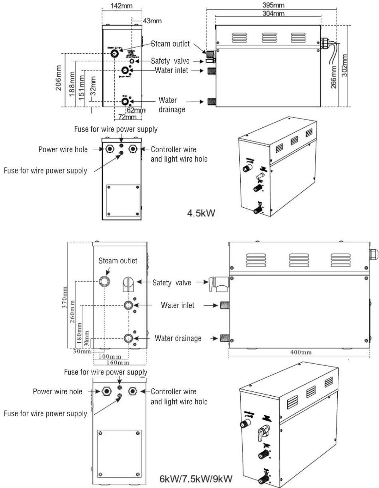
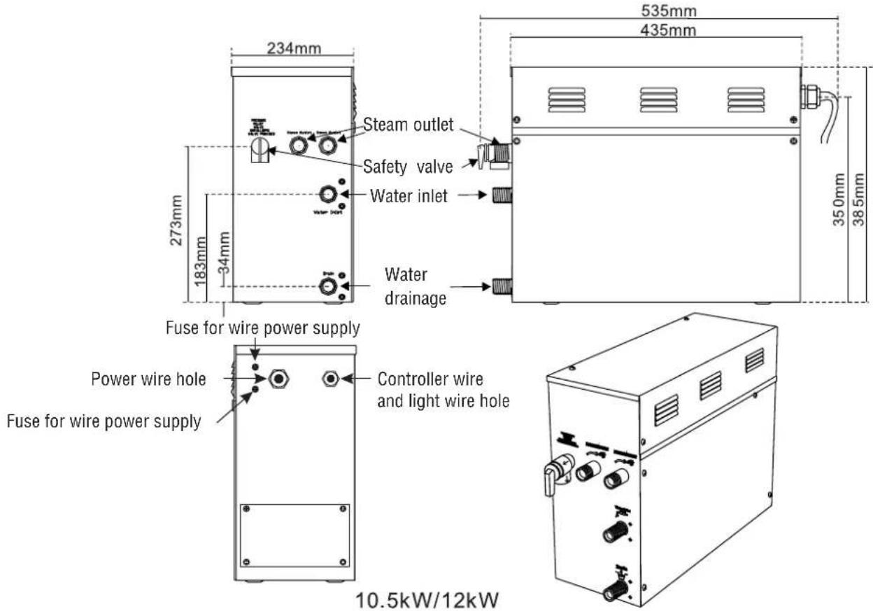
ATTENTION! To facilitate maintenance, keep the steam engine clean. If the information provided is limited, do not operate on the pipeline and electric equipment arbitrarily as shown in the figure for proportion.
ELECTRICAL REQUIREMENTS
ELECTRICAL SUPPLY CIRCUITRY
- Test the voltage of the power supply and make sure suitable voltage is used for the steam generator.
- or local electricity consumption code for the specifications. Refer to the ammeter for the ampere.
- Connect suitably sized equipment grounding wire into the ground terminal
- All the connections must be in accordance with national and local electricity consumption codes and be
Ampere Meter
| Type | Power KW | Electricity supply (1PH) | Electricity current(A) | Specifications for power wire (AW G) |
| B-450 | 4.5 | 240V | 19 | 12 |
| B-600 | 6 | 240V | 25 | 10 |
| B-750 | 7.5 | 240V | 32 | 8 |
| B-900 | 9 | 240V | 38 | 8 |
| B-1050 | 10.5 | 240V | 44 | 6 |
| B-1200 | 12 | 240V | 50 | 6 |
installed by professional electricians. The data provided above is for 240V single-phased motors. Install an independent circuit breaker between supply line and steam generator. Install a power disconnect within sight of steam generator to cut-off power when not in use. Page 9
INSTALLATION DRAWING OF STEAM GENERATOR
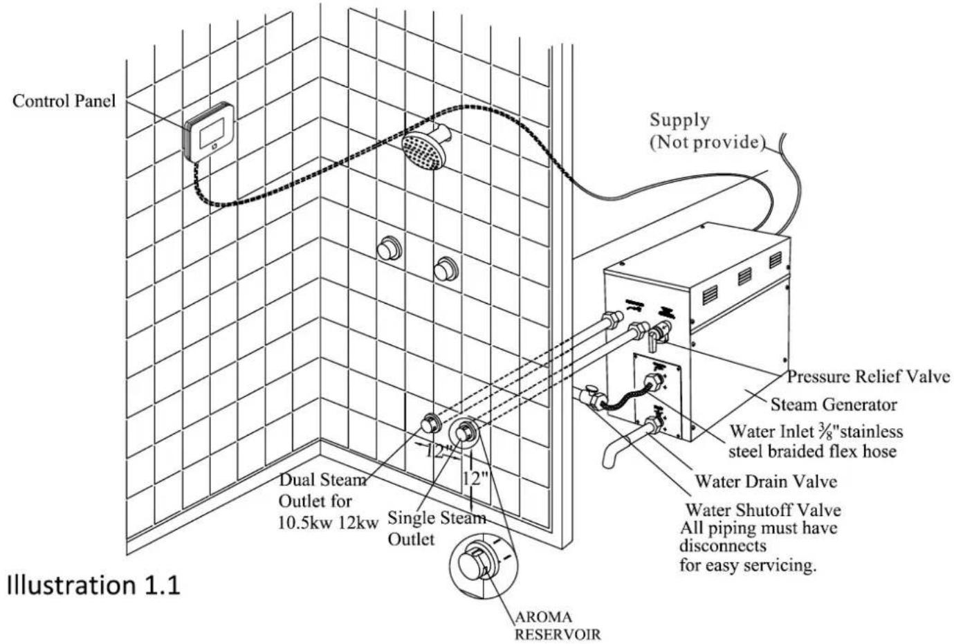
ATTENTION! The drawing is only for explanation purposes. As for practical design of steam room, please consult with a qualified designer, architect or builder.
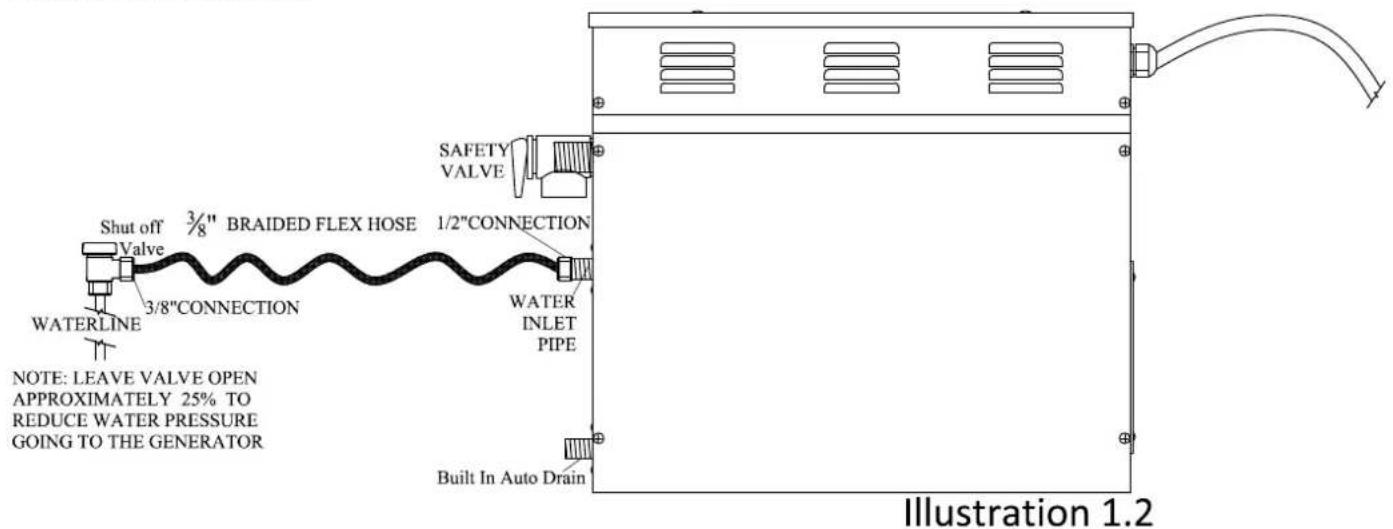

ATTENTION! The drawing is only for explanation purposes, please consult with a qualified designer, architect or builder.
IMPORTANT! All pipe connections should have unions and adapters for easy disconnect.
ATTENTION! Proper installation is a critical requirement per the SteamSpa Warranty terms and conditions. A licensed professional must be used to ensure proper installation. A quick release system, pressure reducing valve, inline water filter and regular maintenance are required.
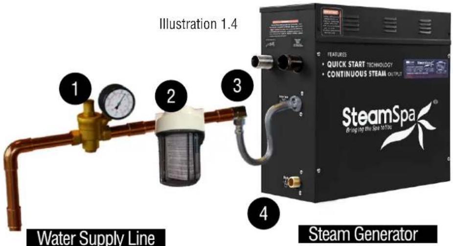
WARNING! Water pressure should reduced to 15 PSI for proper generator operation and to avoid leaks or crack in water filter. Installation must be done in the following order:
1 Pressure Reducing Valve*
2 Water Filter
3 Quick Shut-off Valve*
4 Steel Braided Flex-Hose*
* Available with the Quick Connect Install Kit
INSTALLATION DRAWING OF DUAL STEAM GENERATORS
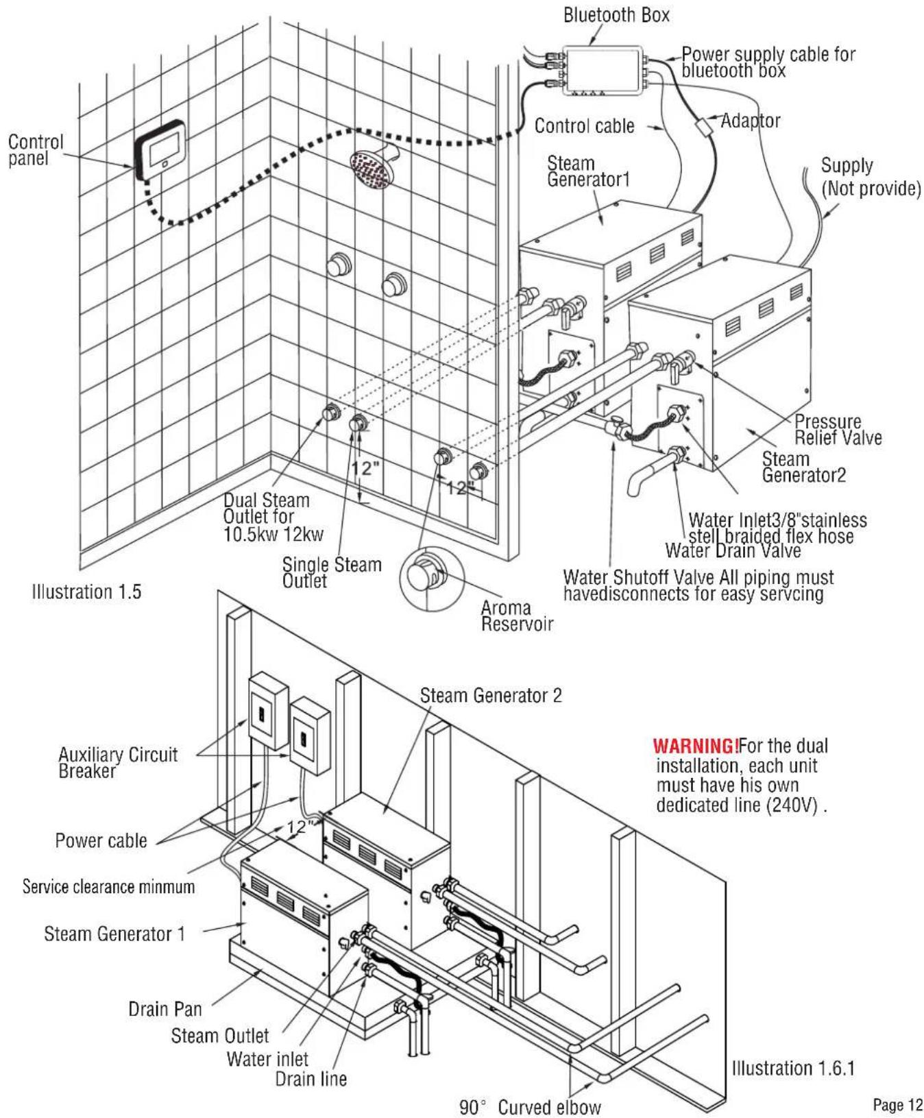


ATTENTION! The illustration is just an example; the practical installation must comply with the nation's electrical criteria, and be done by a professional electrician.
The steam generator maybe installed in these location.
- In closet located behind the shower.
- In Attic
ATTENTION! If the installation of the steam generator will be more than 10 to 15 feet away from the steam room. It is recommended to increase the size of the generator 1 or 2 kilowatts higher to increase the steam flow.
PLUMBING INSTALLATION
WARNING! The installation of all water supply lines should be in accordance to all national and local codes by a licensed plumber.
- Use unions when connecting pipes.
- Use brass pipes or copper pipe only. Do not use black and galvanized or PVC pipes.
ATTENTION! Please ensure a quick connect and release system in employed when installing steam generator to plumbing. Doing so will ensure quick and easy access to the generator for regular care and maintenance and is a critical condition for an active SteamSpa Warranty protection.
WATER SUPPLY PIPE (1/2")
Connect pressure reducing valve with pressure gauge, water filter, shut-off valve, flxe-hose between hot water or cold water pipes and generator. See page 10 illustration 1.2 and page 11 illustration 1.4.
ATTENTION!
- The inlet water should not exceed 160Firc .
- The shut off valve should be installed in a place where it is easily accessible.
- Flush the water supply line completely before connecting the water pipe to the steam generator, to remove any sediments in the water.
- The shut off valve should be open approximately 25% to reduce water pressure to the generator. The water pressure the generator should be between 15 to 20 PSI. if necessary, decrease the pressure accordingly.
- A hydro pneumatic pressure reducing valve must be installed. The SteamSpa quick release & pressure reducing kit comes with a pressure reducing device calibrated to work with any SteamSpa generator unit.
- Do not use PEX or PVC tubing.
INLINE WATER FILTER
WARNING! When installing an Inline Water Filter it is imperative that the water pressure entering the filter is reduced to 15 to 20 PSI to avoid any leaks or cracks.
STEAM PIPE (3/4")
- Do not install any stop valves in the steam pipes. The steam can never be obstructed.
- Install a 3/4" copper or brass pipe between the steam generator and the steam nozzle.
- If needed, the heat insulation material used to insulate the steam pipe should be resistant to temperatures as high as 240F or higher.
- The shorter the distance, the better. Use curved elbows when connecting pipes to allow the steam to flow smoothly through the steam pipe.
- The steam line must slope to allow condensation to drain into the tank or room.
- There must be no dips in the steam line. Low areas may collect condensation and cause faulty operation or cause hot water to spit into the room.
STEAM HEAD (3/4")
ATTENTION! Steam Head and the steam outlet gets very hot, try to avoid installing the steam head in a position which will easily come into contact with the person bathing.
-
Install the steam head approximately 12 inches above the ground floor. If the steam room material is acrylic or non-heat-resistant sheet, please consult with material manufacturer about steam room applications.
-
The steam head outlet should be installed face down. To prevent scalding bather with steam or water.
ATTENTION! Tighten steam head by hand. Do not use a spanner or other tools, use a little soap water and soft sponge to wipe, and do not use erosive chemical solutions or crude cleaning tools.
IMPORTANT!
- Please consult manufacturer of materials like acrylic, fiber glass or other anti-heat sheet about the installation of the steam head.
- In the entire steam room, it is required that steam does not leak out. The pipes, its accessories and the holes should be air proof by applying sealant so that no steam will enter the holes in the wall.
DRAINPIPE (1/2")
ACCORDING TO THE NATIONAL AND LOCAL PLUMBING CODES: The steam generator drain valve should be equipped with a drainpipe. The steam generator drains the water by gravity. Check local code requirements for drain valves. Do not connect the safety valve or steam line to drain line.
SAFETY VALVE (3/4")
- Safety valve is an automatic system that is actuated by pressure in order to prevent steam pressure increasing in the interior of the generator.
- The pressure limit range of the safety valve is 15 PSI and the pressure will begin to decrease if pressure should come over this value.
- If it is allowed by local codes, provide the safety valve with exterior drainpipe.
- Do not dismantle the pressure relief valve while generator is in operation.
- To maintain the proper automatic operation of the safety valve, make sure the safety valve connection pipe is smooth.
ASSEMBLY GRAPH FOR POWER WIRE

ATTENTION! To avoid damage to the equipment, do not connect electric current directly to heating elements.
WARNING! This graph is for explanation only. For actual installation, refer to national and local electricity consumption codes by professional electricians.
WIRING DIAGRAM

flowchart
graph TD
    A["Water Level Senor"] --> B["Red(ShortPin)"]
    A --> C["Black(LongPin)"]
    A --> D["Yellow(MiddlePin)"]
    B --> E["Fill water valve"]
    C --> F["Drain water valve"]
    D --> G["Yellow"]
    H["To Control Panel"] --> I["J1"]
    J["Terminal Block Yellow/Green"] --> K["Supply L2 L1 G"]
    I --> L["Red Black"]
    K --> M["Red Black"]
    L --> N["White"]
    M --> O["Black"]
    N --> P["Red"]
    O --> Q["Black"]
    P --> R["Red"]
    Q --> S["Red"]
    R --> T["Red"]
    S --> U["Red"]
B-450

flowchart
graph TD
    A["Water Level Senor"] --> B["Black"]
    A --> C["Red"]
    A --> D["Yellow"]
    B --> E["Fill water valve"]
    C --> F["Drain water valve"]
    D --> G["Drain water valve"]
    H["To Control Panel"] --> I["J1"]
    H --> J["J2"]
    H --> K["White"]
    H --> L["Black"]
    M["Terminal Block Yellow/Green"] --> N["Supply L2 L1 G"]
    O["Red"] --> P["Red"]
    Q["Red"] --> R["Red"]
    S["Red"] --> T["Red"]
    U["Red"] --> V["Red"]
    W["Red"] --> X["Red"]
    Y["Red"] --> Z["Red"]
    style A fill:#f9f,stroke:#333
    style M fill:#ccf,stroke:#333
    style O fill:#cfc,stroke:#333
    style P fill:#fcc,stroke:#333
    style Q fill:#fcc,stroke:#333
    style R fill:#fcc,stroke:#333
    style S fill:#fcc,stroke:#333
    style T fill:#fcc,stroke:#333
    style U fill:#fcc,stroke:#333
    style V fill:#fcc,stroke:#333
    style W fill:#fcc,stroke:#333
    style X fill:#fcc,stroke:#333
    style Y fill:#fcc,stroke:#333
    style Z fill:#fcc,stroke:#333
B-600
WIRING DIAGRAM

flowchart
graph TD
    A["Water Level Senor"] --> B["Black ShortPin"]
    A --> C["Black LongPin"]
    A --> D["Yellow MiddlePin"]
    B --> E["Fill water valve"]
    C --> F["Drain water valve"]
    D --> G["Red"]
    E --> H["White"]
    F --> I["Red"]
    G --> J["Black"]
    H --> K["To Control Panel"]
    I --> K
    J --> K
    K --> L["Supply"]
    L --> M["L2 L1 G Terminal Block Yellow/Green"]
    K --> N["Red"]
    K --> O["Black"]
    K --> P["Black"]
    K --> Q["Black"]
    K --> R["Red"]
    K --> S["Red"]
    K --> T["Red"]
    K --> U["Red"]
    K --> V["Red"]
B-750 B-900

flowchart
graph TD
    A["Water Level Senor"] --> B["Black"]
    A --> C["Red"]
    A --> D["Yellow"]
    A --> E["Fill water valve"]
    A --> F["Drain water valve"]
    G["To Control Panel"] --> H["J1"]
    G --> I["J2"]
    G --> J["White"]
    G --> K["Black"]
    L["Terminal Block"] --> M["Supply"]
    L --> N["Red"]
    L --> O["Red"]
    L --> P["Red"]
    Q["Yellow/Green"] --> R["Red"]
    S["Red/ShortPin"] --> T["Black(LongPin)"]
    U["Red/ShortPin"] --> V["Yellow(MiddlePin)"]
B-1050 B-1200
STEAM GENERATOR DISSECTION DIAGRAM

- ENCLOSURE
- INSULATION BRACKET
- CIRCUIT BOARD
- STEAM OUTLET
- PRESSURE RELIEF VALVE
-
WATER FILL VALVE
-
WATER DRAIN VALVE
- SUBSIDIARY WATER TANK
- MAIN WATER TANK
- HEATING ELEMENT
11.221 F HI-LIMIT -
TRANSFORMER
-
TERMINAL BLOCK
- FUSE
- GROUND WIRE CONNECTOR
- RELAY
- WATER LEVEL SENSOR
CARE & USE FOR THE CONTROL PANEL
- Use soft cloth with a little soap water to clean the control panel.
- Do not use crude cleaning tools.
- If the decorating facade is damaged, contact service electrician to change it.
Do not install any SteamSpa controls without reading and understanding the SteamSpa generator Installation and Instruction manual. Failure to read and understand these instructions will result in inoperative control, generator, hazardous overheating, and/or inadequate heating of the steam room.
Do not route control wiring inside or close to power lines conduit, hot water or steam piping. Doing so may result in an inoperative control, generator, and/or hazardous installation.
Do not install SteamSpa controls with other than SteamSpa compatible steam generators. Doing so may result in possible generator damage or inoperative installation.
Single Control Panel with Temperature sensor must be installed inside bathing area 5 feet above floor. Do not install Control directly above Steam Head or below shower head but rather in the seating area on a vertical wall. Doing so may result in improper temperature reading and/or inoperable control.
Turn power to the steam generator off before connecting the control to the generator. Failure to turn the power off generator prior to connecting controls will result in an inoperable control.
Discontinue use of the steam generator or control if the steam generator is damaged. Continue to do so may result in an inoperative or hazardous installation.
natural_image
Simple graphic with a gray rectangle and an orange square icon, no text or symbols present.CONTROLLER SPECS

CONTROL PANEL INSTALLATION INSTRUCTIONS
STEP ONE
Determine the installation location of the control panel. The master control panel is designed to be installed in the steam room only, please install:
- 4-5 feet from the ground.
- Keep away from the steam head and do not expose under the direct spray of steam.
- Install in the perpendicular wall.
- The position of installation should facilitate easy operation and convenient wiring.
A. Recess mount onto the wall using the control box.

flowchart
graph LR
    A["Open an hole on the wall for wall box (INCH)"] --> B["Lead to steam generator"]
    B --> C["47.2-50.1INCH from the ground"]
    C --> D["Recess mount the wall box into wall"]
    D --> E["Control panel"]
    E --> F["Tear the 0.12INCH glue on the controller and coated with a circle of glass glue around"]
    F --> G["The back of the controller"]
    G --> H["Put the control panel into the wall box"]
B. Recess mount with mounting plate.

C. Using the double-sided adhesive.

flowchart
graph LR
    A["Open an hole as picture shown"] --> B["Tear the 0.12INCH glue on the controller and coated with a circle of glass glue around"]
    B --> C["47.2-50.1INCH from the ground"]
    C --> D["Control panel sealing glue"]
    D --> E["nut"]
    E --> F["TEMP sensor holder"]
    F --> G["φ 1.1""]
REMARKS: The control panel comes with internal TEMP sensor, but external TEMP sensor is optional, when control panel is installed inside steam room, Internal TEMP sensor is ok. when control panel is installed outside steam room, external TEMP sensor is necessary. Page 21
FUNCTIONS

LED LIGHT

STEAM

BLUETOOTH

CHROMA LIGHT

AROMA PUMP
OPERATIONAL APPROACH
1. START-UP/SWITCH OFF
(1) POWER ON
The buzzer of the display box will buzz after connection to power source.
(2) START-UP
When the system is under stand-by mode, press the ☐ key to start-up. The current ambient temperature in the room and bluetooth music icon will be displayed on the screen as shown in Figure 1. After the interface is fully displayed, press the function key on the screen to unlock.
If the user has set a scheduled start up function, when the scheduled time is reached, the system will start-up automatically and the steam function will be activated.
(3) POWER-OFF
Press the ☐ key to close the system. The clock will be displayed if the function is set in the system, otherwise, it won't be displayed on the screen.
If a pre-set shut off time has been scheduled, the system will power-off automatically when the pre-set time is reached. (The system will also shut down 2 minutes after the steam function has ended.)
2. Control of White LED Light (If Equipped)
After power-on, the lighting section interface is shown in Figure 4 as follows: Press to turn on the light; Press to turn off the light.
3. Control of Color Changing Light (If Equipped)
When the system is power-on, enter in the lighting interface as shown in Figure 4: Press 🔒 key to turn on the Color-Changing light, and then press ◀ ▶ key to change the color of the light. Press the 🔒 key to turn off the Colored-light Function after the color-changing light function is started.
4. STEAM FUNCTION
Select the steam interface shown in Figure 1 after power-on: Press to start the steam function; The steam key is shown as Figure ; Press the again to stop the steam Function.
Steam temperature setting: Set temperature by pressing the key of "temperature+" or "temperature-". Set the temperature range within 10-43 degrees Celsius by increments of 1 degree. (Fahrenheit range: 50-110 degrees, in increments of 1 degree.) Steam time Settings: Set a 5-60-minute of steaming time in increments of 5 minutes by pressing the key of "time+" or "time-". Revise the system shutdown time while setting the steam time.
Save user information: Through the user interface shown in Figure 5; select the user bar to be used by pressing △ or ▼ key, Then the temperature parameters and timing parameters by pressing ▶ and will be saved in this bar.
Read user information: Through the user interface shown in Figure 5: Select the user bar to be read by pressing △ or ▽ key, and → to select the saved user setting. Note, the steam function shall be activated in advance.
Scheduled start-up setting: Select the function bar of "Working Mode" shown in Figure 6 on the setting interface, press OK key to enter the interface shown in Figure 7 to set relative parameters.
① Time setting: Stop the cursor on the "Timing" bar by pressing △ or ▽ key, set hours by pressing ◀ key, and minutes by ▶ key. The parameters are set in loop with 1 hour increments and a range of 0-23 hours; And a 10 minute increments and a range of 0-50 minutes.
② Working mode: Move the cursor from Sunday to Monday bar with △▼ key, Then select the function options of: off, one-time schedule, or repeat schedule with ◀▼ key. If the one-time schedule mode is selected, the system will set the change the setting to “off” automatically after one-time scheduled cycle is complete.
③ Save information by pressing ☐ key and run as per the set parameters. Exit the setting interface by pressing the ☐ key.
④ When system is running under the scheduled start-up mode, the temperature and steamer working time set by user1 shall be taken as default. For example, if the temperature is 110irc F and the working time is 30 minutes set by user1, then the temperature shall be 110irc F and the working time shall be 30 minutes under the scheduled start-up mode. If the working time is adjusted after start-up, the scheduled shut off time shall subject to the final set time.
⑤ Drain 5 minutes automatically after 30 minutes from system power off;
⑥ When control panel is on but steam function still not be activated, keep pressing aroma pump button * on main interface to drain water manually. when water drain, pressing aroma pump button * or steam button 🖱️ , water drain stop.
5.SHIFT TEMPERATURE UNIT
Selection"F/°C" function bar on the setting interface shown in fig.6 after power on, press OK key to enter the interface shown in Figure 9. Press the "OK" key again to shift between degrees Celsius and Fahrenheit.
6. RESTORE FACTORY SETTINGS FUNCTION
Select "Factory Setting" bar on the setting interface, and press the "OK" key shortly to restore the factory parameter. The steam control temperature will return to 110irc F and the steaming time to 30 minutes.
7. SET REAL-TIME CLOCK
Select the "Real Time" function through setting interface shown in Figure 6 after power on, and press OK key to enter the interface shown in Figure 8. Move the cursor to the parameters need to be set by pressing ▶ ▶ key, e.g.: Hour, minute, date, month, year, displaying time or not after power off etc. Then adjust the parameters by pressing △ ▽ key. The parameter of "week" will be calculated automatically by date input system. Press the "OK" key to save the parameters set. Exit the interface by pressing "ESC" key. The parameters won't be saved if the "OK" key is not pressed before pressing "ESC" key.
Remarks: The real-time clock shall be recalibrated after they power interruption of the system is more than one week.
8.BLUETOOTH MUSIC FUNCTION
(1) Start of the bluetooth music function: Connect the bluetooth of the cell phone after power on, select the interface as shown in Figure 3 and press % key to power on/off the bluetooth music function. The key state prompts under play mode are shown as %.
(2) Song switching: When the bluetooth music is playing: It can be switched to the previous song by pressing key and the next song by pressing key.
(3) Volume adjustment: The music volume can be adjusted by pressing ☐ Vol- key on the interface of bluetooth. The volume range (0-15) e.g. "10dB" may be shown on the screen. It will be recalibrated after they power interruption of the system is more than one week. Page 24
(4) The bluetooth connection will be cut off automatically 10 seconds after system power-off. When the cell phone is going to be restarted after 10 seconds, the bluetooth shall be connected through the cell phone, then start the music player to play the music. The bluetooth can be operated normally only after the synchronous success. The bluetooth equipment was named as "sauna".
(5) The bluetooth status indicating icon ✦ will be flash on the bluetooth interface when the bluetooth equipment is not connected, then, otherwise, it will stop flashing.
9. Aroma pump
when steam function working, touch button

to switch on/off aroma pump.
10. Trouble shooting
When there is a fault detected by system when reality set don't tip as shown in Figure 1: fault code information
| Error code | Fault description | Trouble shooting |
| 02 | Steam generator and control panel communication failure | 1)cable connection is good or not.2) IP address match or not. |
| 05/15 | Water inlet problem | Pls check whether there is water supply or the water inlet valve working or not. |
| 08 | Temperature sensor open circuit | Pls check the TEMP sensor cable,if not good,pls kindly change the TEMP sensor |
| 09 | Temperature sensor short circuit | Pls check the TEMP sensor cable,if not good,pls kindly change the TEMP sensor |
Outside secondary On/Off Control
Reminder: Outside secondary On/Off Control is not standard part for main keypad. it's optional.

natural_image
Circular black button with a small orange square icon at center (no text or symbols)Figure11: Outside secondary On/Off Control
1、When system power off, touching outside secondary On/Off control get normal light and steam function works.

to
2、When system power on, touch button to stop steam and normal light. button backlight off at same time.
3、Button is purple color for 2 seconds once sub-keypad power on. When outside secondary On/Off control can't receive signal from main keypad in 5 seconds. Blue button backlight is flash. When main keypad malfunction, red button backlight flash.
When secondary control get electricity, steam function still not work, button backlight is light blue. When steam works and room temperature is 1celsius degree lower than preset room temperature, button backlight is purple. When room temperature is 1celsius degree higher than preset room temperature, button backlight is red.
TECHNICAL PARAMETERS
| Working conditions and characteristics | |||
| Rated voltage | AC240/AC220 | Rated frequency | 50/60Hz |
| Rated current | Rated power | ||
| Insulation resistance | Waterproof grade | ||
| Load the configuration parameters | ||||
| Load category | Rated load voltage | Rated load frequency | Rated load power | Other |
| Bluetooth music box | AC220 | 50/60Hz | 8W*2 | |
| Chroma light | DC12V | ≤5W | ||
| Light | AC12V | ≤3W | ||
| Solenoid valve | DC12V | 5W*2 | ||
INSTALLING LIGHT
CAUTION! Installer must take some moisture proof measures in the process of installation. Electrophorus components cannot be exposed to moisture, as it will cause damage to the light components causing a possible short circuit.
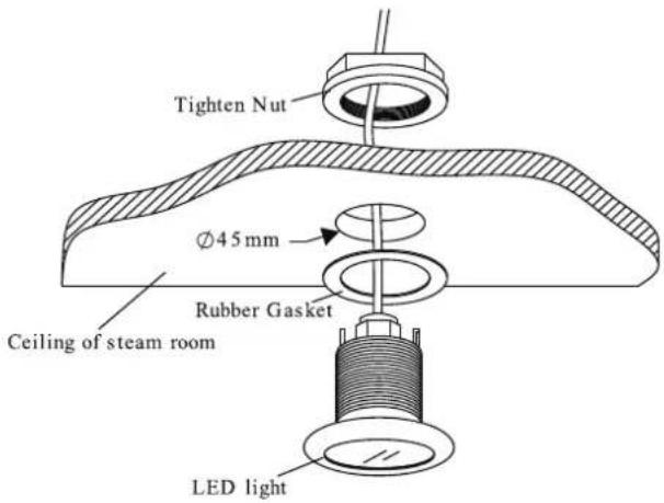
INSTALLING SPEAKERS
- Chose a proper place on ceiling inside the steam room.
- Open 4 holes with 10mm depth and 5mm diameter.
- Fix the speaker and grill on the ceiling with screws as picture attached. pls kindly choose the screws according to the thickness of the ceiling or the plate where to fix the speaker. for example, if the ceiling thickness is 1/2", we shall use #4 x 1/2" phillips pan head self-tapping screws. if the ceiling thickness is 3/8", we shall use #4 x 3/8" phillips pan head self-tapping screws. the screws length should be neither less than 2mm nor longer than the ceiling thickness. when the thickness of ceiling is less than 4mm, 1pc or more #4 flat washer between screw and the cover shall be added.

TESTING THE MACHINE
- Make sure the power switch of the control panel is turned on (the control panel displays —), Then the water supply valve will open.
- Press the steam switch, the control panel will display the temperature of the environment, the steam engine begins to input water to start the steam function.
- When there is steam output, press again, the steam will stop and the light will go off automatically.
- Press the button to start the steam, the steam will come out of the steam generator in no more than 1-2 minute. As time goes on, the temperature displayed in the control panel will rise with the temperature in the room before it stops and stays at the set temperature.
- Based on different requirements of the user for temperature and steam time, the control panel can adjust temperature and steam time.
- When the set steam time is due, the system will shut off the steam and light function automatically to stop water input and steam production.
- 30 minutes after the steam is shut off, the system will start drainage automatically for 7 minutes. After testing the machine and it is working properly. Then the machine can be operated normally.
WARNING! Do not dismantle the safety pressure decrease valve arbitrarily.
IMPORTANT! Do not switch the water input pipe when the steam generator is working.
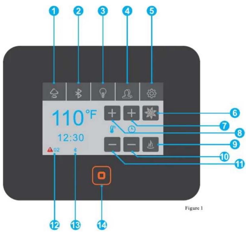
- Steam Controls
- Bluetooth Controls
- Light Controls
- User Presents
- Settings
- Aroma Pump
- Steam Time +
- Steam TEMP.+
- Start Steam Production
- Steam Time -
- Steam TEMP.-
- Error Codes
- Bluetooth Icon
- Power On Off
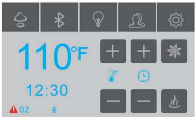
figure1 - main screen
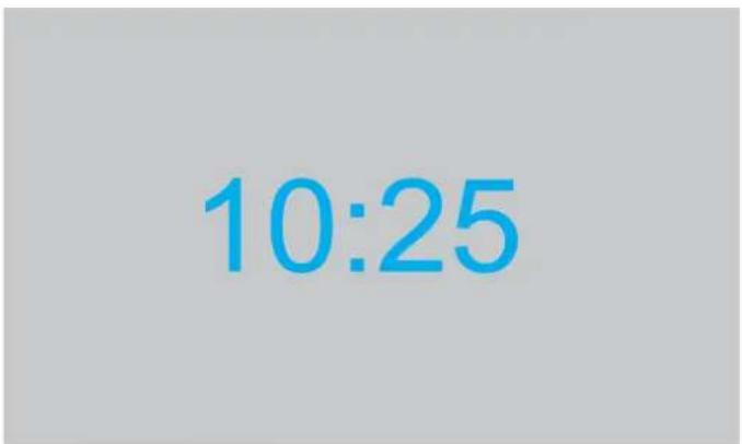
figure 2 - clock screen

figure 3 - bluetooth screen

figure 4 - light screen
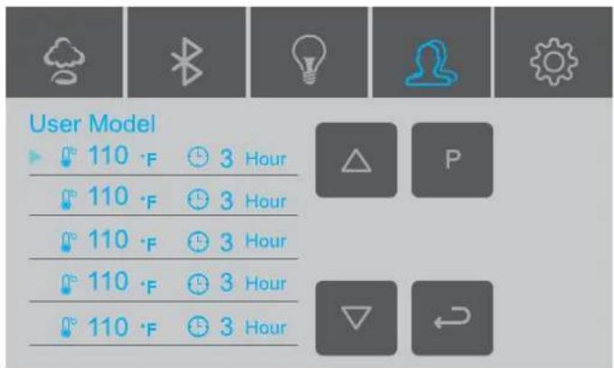
figure 5 - user presents

figure6 - settings
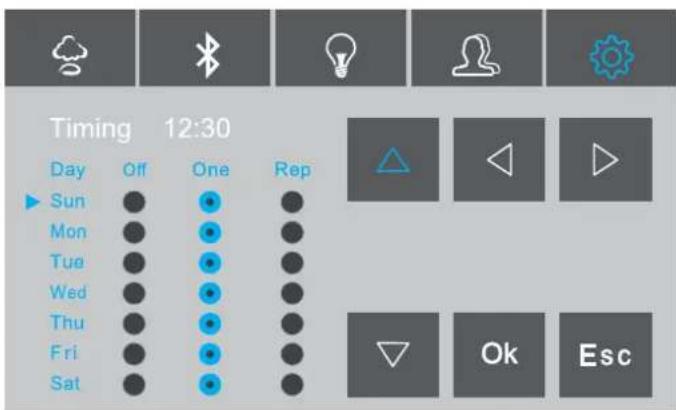
figure 7 - schedule screen

figure 8 - clock settings

figure 9 - temp settings
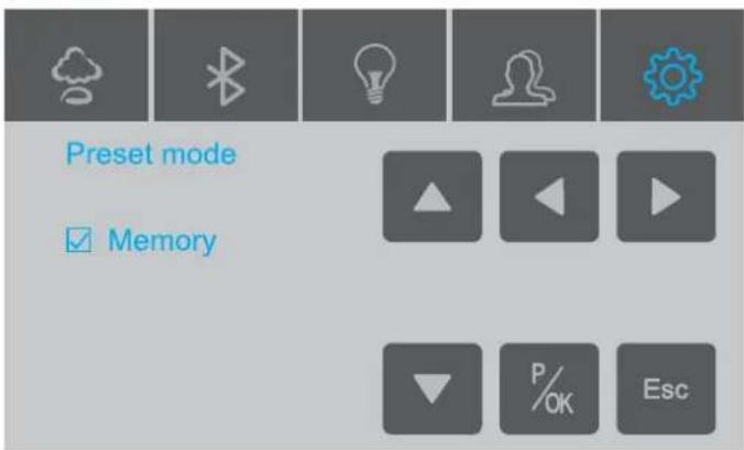
figure 10 - presents mode
APP MANUAL FOR STEAM GENERATOR
With the addition of the WF50 WIFI box, the steam generator be controlled remotely via our APP on your mobile. Please note that you will need an existing wireless router.
ATTENTION: WIFI box is compatible with SS-BCT01BK control panel only, APP instructions part is only for user who purchased the WiFi box.
1. DOWNLOAD APP ON MOBILE
A. For Android phone,
Scan QR to install APP.
B. For IOS Phone(Iphone)
Search "Smart Life" in APP STORE directly to download APP

Android QR Code
C. Enter download interface as show on pictures, click "download", choose "Installation" to download the APP can be downloaded and installed.

flowchart
graph LR
    A["smartapp.tuya.com/smartlife"] --> B["Formal version"]
    B --> C["Download"]
    D["Smart Life Installation source: Browser"] --> E["Installing..."]
    E --> F["CANCEL"]
2. USER REGISTRATION AND SIGN IN
Click APP logo "Smart Life" to enter into login interface as picture shown, if it's first time login, need to register new user account as guide.
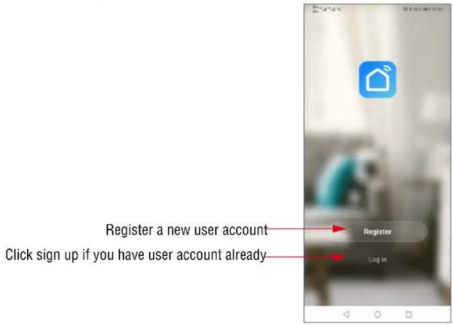
3.Adding your steam generator to the APP List
On the first time use, you have to add your steam generator to the device list.

Click"Add Device"
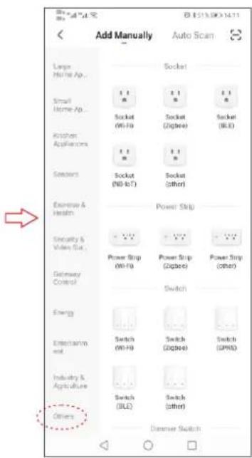
Click again "others"
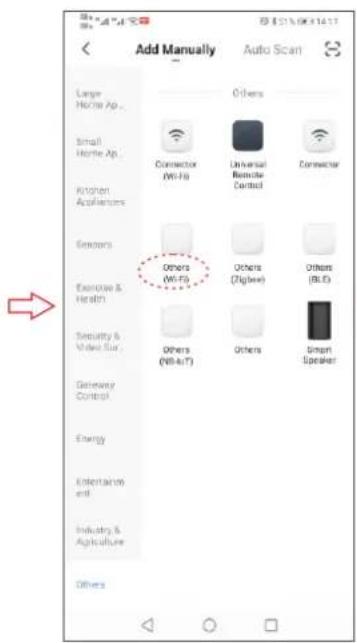
In others to choose "others (Wi-Fi)"

Input WIFI password Click"Next"
Operations are needed as follows before inputting the password and clicking the Next" button.
- Power on the control panel and proceed steps as follows in the first 5 minutes.
- Touch the icon ⚙️ to enter the setting interface as displayed in picture.
- Move the arrow to "factory settings".
- Keep pressing button "OK" for 2 seconds, you will hear a "BEE" sound, the system is now in the WIFI matching state, you can see LED on WIFI box flashing.

When steam generator is in matching state, please enter WIFI password on APP click "Next" to add steam generator in APP and enter into product operation interface.

flowchart
graph LR
A["Reset the device first.<br>Please turn on the device and confirm that indicator is blinking fast.<br>Attention: please complete passing process within 3 minutes after device reset."] --> B["Resetting Devices"]
B --> C["Confirm indicator rapidly blink<br>Next"]
C --> D["Change device name<br>After steam generator added in the list.<br>Click "Completed""]
D --> E["Create a new device name with Steam Generator"]
E --> F["Enter operation interface<br>Click device, Enter Home location for more information"]
F --> G["Shining Invitations<br>All Devices"]
G --> H["On/Off Switch"]
- OPERATION INTERFACE OF STEAM GENERATOR

5.FUNCTION
A. Steam temperature Setting
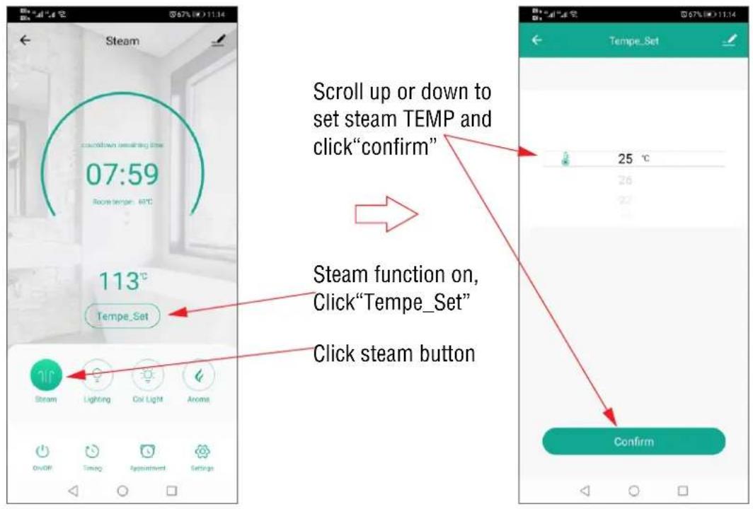
B. Working Time Setting

C. Appointment Setting

D. Chroma Light

Open the steam and chroma light at same time, press relative color icon to set light color we want. When we choose the chroma light icon, light change color automatically.
E. Normal Light and Aroma
Steam function on, click on the "light" button switch on/off the normal light.
When steam function on, click aroma button to switch on/off the aroma function.
F. Setting
- Auto. clean function
When steam function off, click the "Automatic wash" to start cleaning function.
- Temperature unit switch
Click temperature scale switch, the temperature unit can be switched between Celsius and Fahrenheit.
- Real-time Clock
Click the real time clock to get real clock time is same as the clock shows on keypad.
G. Parameter Settings
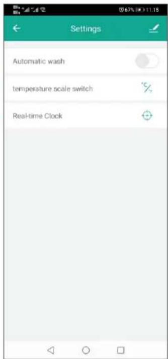

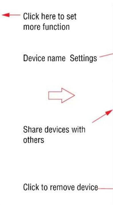
flowchart
graph TD
    A["Device name Settings"] --> B["Share devices with others"]
    B --> C["Click to remove device"]
    D["Click here to set more function"] --> A

H. Share device and remove device


Enter the user account who you would like to share the device with him. But this user account should be registered on "smart life"APP.
After input the user account, click "Done"

STEAM GENERATOR MAINTENANCE
IMPORTANT! The steam generator automatically performs a water discharge operation after each use.
- Wait for the completion of automatic water discharge after each time using the steam generator to make sure the water in the tank is discharged completely before cutting off power supply.
- There should not be any leakage or damage among the steam generator, steam nozzle, components and pipes. They should be checked and repaired annually.
- Clean the water supply pipes of the steam generator once a year.
- Check all the pipe connections, to ensure wether they are tight and not damaged due to overheat.
- It is recommended that the water sensor prong gets clean once every six month.
a. Remove the casing of the generator.
b. Locate the water sensor.
c. Label each electrical connections then carefully remove all connections.
d. With a wrench or a 32mm ratchet socket carefully unscrew the water senor.
e. Thoroughly clean any residue buildup accumulated on the prong.

natural_image
Technical line drawing of an internal electrical enclosure with wiring and components, showing internal wiring connections (no text or labels)TROUBLE SHOOTING GENERATOR
| PROBLEM | POSSIBLE CAUSES | SOLUTIONS |
| The machine does not start when powered | 1. Burned out fused2. The electrical wiring became loose3. Control panel connection loose | 1. Replace fuse (0.8A/240V)2. Cut power Supply and reconnect wiring3. Reconnect control panel and reset4. Controller (turn off and on) |
| Breakers are tripping | 1. Check gauge size2. Damaged heating element | 1. Replace wire with correct gauge2. Replace heating element |
| When the machine is started, hot water comes out with little or no steam | 1. Check inlet valve2. Check cable pins | 1. Clean or replace valve2. Clean or replace pins |
| The display screen on the control panel does not display anything | 1. The control panel wire is not connected properly2. Trouble with generator motherboard | 1. Check whether the connection plug between the control panel and the generator has become loose, and whether the power circuitry has good contact2. Replace the motherboard |
| Water leakage | 1. The water pipe connector becomes loose or pipe is broken.2. Water leakage in the water input valve or the water drainage valve | 1. Tighten the loose connection or change the broken pipe2. Change the water input valve or the water drainage valve |
| No steam when starting the machine | 1. No electricity2. No water3. The set temperature is too low4. Wiring connection problem | 1. Check the power supply and connections2. Check the water input pipe and water input valve3. Reset the temperature4. Check wiring connection and tighten |
| The steam does not come out, the water sounds in the machine | 1. Check heating element | 1. Clean or replace heating elements |
| Light doesn't turn on | 1. Bad LED light bulb2. Wiring connection improperly connected or light cable damage | 1. Change LED light bulb2. Tighten connection or replace light cable |
| Cold water is coming from the steam head | 1. The water sensor cable is loose or water level sensor is defected2. Check cable pins3. Check inlet water valve | 1. Make sure that the water level cable isn't loose if the cable is well connected replace the water sensor2. Replace cables3. Clean or replace inlet valve |
| 05 Error Code | 1. Water inlet problem | 1. Check water supply for proper flow2. Check inlet valve for blackage. It many need cleaning or replacement. |
TECHNICAL PARAMETERS
| Type | 4.5KW | 6KW | 7.5KW | 9KW | 10.5KW | 12KW |
| Power (KW) | 4.5 | 6 | 7.5 | 9 | 10.5 | 12 |
| Voltage (V) | 240 | 240 | 240 | 240 | 240 | 240 |
| Current (A) | 19 | 25 | 32 | 38 | 44 | 50 |
| Errors Range | +10% | +10% | +10% | +10% | +10% | +10% |
| Anti-Static Constant | >1500V | >1500V | >1500V | >1500V | >1500V | >1500V |
| Insulation Resistance | >20M Ω | >20M Ω | >20M Ω | >20M Ω | >20M Ω | >20M Ω |
| Head Lamp | ~12V/3W | ~12V/3W | ~12V/3W | ~12V/3W | ~12V/3W | ~12V/3W |
| Time Set Range (min) | 1-60 | 1-60 | 1-60 | 1-60 | 1-60 | 1-60 |
| Steam Press (psi) | 3 | 4 | 4 | 4 | 5 | 5 |
| Steam Vol. (cu. in./min) | 9 | 11 | 13 | 16 | 19 | 21 |
| Steam Spray Time (sec) | 100-180 | 180-240 | 150-210 | 120-180 | 170-230 | 150-160 |
| Water Vol. (cu. in.) | 80 | 160 | 160 | 160 | 330 | 330 |
IMPORTANT! The list above is for reference only. Actual checking and repairing should be based on national and local codes, ask professional service personnel to operate.
IMPORTANT! The parameter listed above will vary by geographical location and environment. Please consult a qualified designer and architect for more detailed use.
WIRING CONNECTION DRAWING OF STEAM GENERATOR

flowchart
graph TD
    A["Steam generator"] -->|B 1 u| B["AC240V Fuse"]
    B --> C["Power supply"]
    C --> D["Bluetooth box"]
    D --> E["Adaptor"]
    E --> F["DC12V"]
    F --> G["Light"]
    D --> H["(Optional) WIFI box"]
    H --> I["Secondary key pad (Optional)"]
    I --> J["Speaker 8Ω 10W"]
    I --> K["Speaker 8Ω 10W"]
    D --> L["Aroma pump"]
    L --> M["1.6Ft"]
    M --> N["28Ft"]
    N --> O["1.2Ft"]
    O --> P["1.2Ft"]
    P --> Q["1.2Ft"]
    Q --> R["6.4Ft"]
    R --> S["1.2Ft"]
    S --> T["Main-keypad"]
    D --> U["1.6Ft"]
    U --> V["28Ft"]
    V --> W["1.6Ft"]
    W --> X["Speaker 8Ω 10W"]
    W --> Y["Speaker 8Ω 10W"]
    D --> Z["1.6Ft"]
    Z --> AA["28Ft"]
    AA --> AB["1.6Ft"]
    AB --> AC["Chroma light can connect lights up to 5pcs"]
WIRING CONNECTION DRAWING OF DUAL STEAM GENERATORS
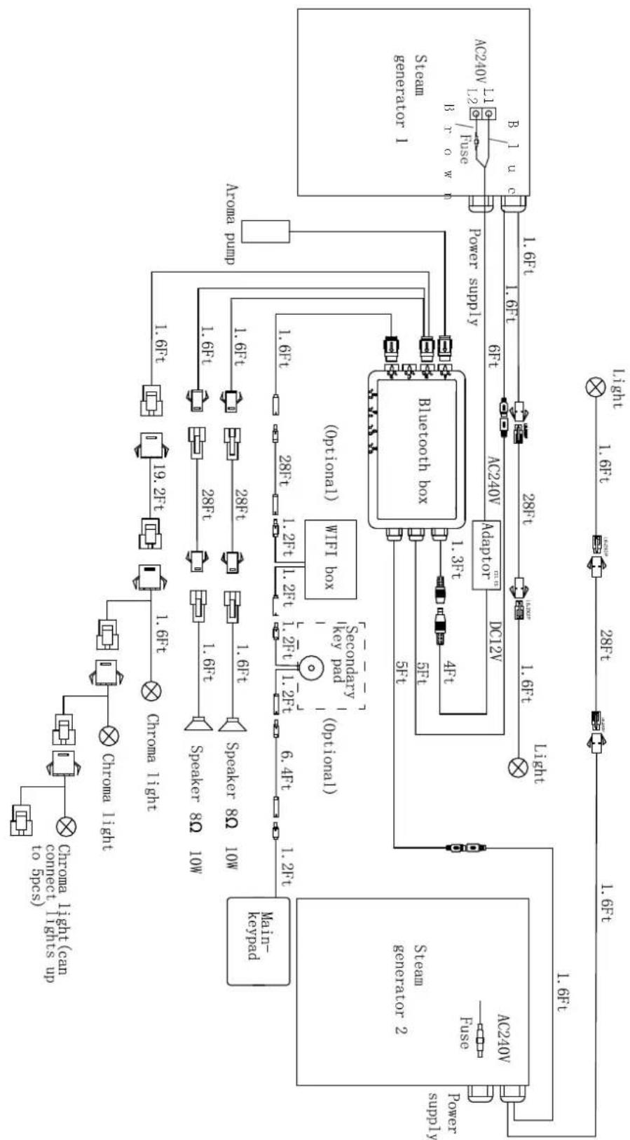
flowchart
graph TD
    A["Steam Generator 1"] --> B["Stem Generator 2"]
    B --> C["Keyboard"]
    C --> D["Motor Pump"]
    D --> E["AWA"]
    E --> F["Bluetooth Box"]
    F --> G["Secondary key pad (Optional)"]
    G --> H["Speaker 80 10W"]
    H --> I["Speaker 80 10W"]
    I --> J["Speaker 80 10W"]
    J --> K["Speaker 80 10W"]
    K --> L["Speaker 80 10W"]
    L --> M["Speaker 80 10W"]
    M --> N["Speaker 80 10W"]
    N --> O["Speaker 80 10W"]
    O --> P["Speaker 80 10W"]
    P --> Q["Speaker 80 10W"]
    Q --> R["Speaker 80 10W"]
    R --> S["Speaker 80 10W"]
    S --> T["Speaker 80 10W"]
    T --> U["Speaker 80 10W"]
    U --> V["Speaker 80 10W"]
    V --> W["Speaker 80 10W"]
    W --> X["Speaker 80 10W"]
    X --> Y["Speaker 80 10W"]
    Y --> Z["Speaker 80 10W"]
    Z --> AA["Speaker 80 10W"]
    AA --> AB["Speaker 80 10W"]
    AB --> AC["Speaker 80 10W"]
    AC --> AD["Speaker 80 10W"]
    AD --> AE["Speaker 80 10W"]
    AE --> AF["Speaker 80 10W"]
    AF --> AG["Speaker 80 10W"]
    AG --> AH["Speaker 80 10W"]
    AH --> AI["Speaker 80 10W"]
    AI --> AJ["Speaker 80 10W"]
    AJ --> AK["Speaker 80 10W"]
    AK --> AL["Speaker 80 10W"]
    AL --> AM["Speaker 80 10W"]
    AM --> AN["Speaker 80 10W"]
    AN --> AO["Speaker 80 10W"]
    AO --> AP["Speaker 80 10W"]
    AP --> AQ["Speaker 80 10W"]
    AQ --> AR["Speaker 80 10W"]
    AR --> AS["Speaker 80 10W"]
    AS --> AT["Speaker 80 10W"]
    AT --> AU["Speaker 80 10W"]
    AU --> AV["Speaker 80 10W"]
    AV --> AW["Speaker 80 10W"]
    AW --> AX["Speaker 80 10W"]
    AX --> AY["Speaker 80 10W"]
    AY --> AZ["Speaker 80 10W"]
    AZ --> BA["Speaker 80 10W"]
    BA --> BB["Speaker 80 10W"]
    BB --> BC["Speaker 80 10W"]
    BC --> BD["Speaker 80 10W"]
    BD --> BE["Speaker 80 10W"]
    BE --> BF["Speaker 80 10W"]
    BF --> BG["Speaker 80 10W"]
    BG --> BH["Speaker 80 10W"]
    BH --> BI["Speaker 80 10W"]
    BI --> BJ["Speaker 80 10W"]
    BJ --> BK["Speaker 80 10W"]
    BK --> BL["Speaker 80 10W"]
    BL --> BM["Speaker 80 10W"]
    BM --> BN["Speaker 80 10W"]
    BN --> BO["Speaker 80 10W"]
    BO --> BP["Speaker 80 10W"]
    BP --> BQ["Speaker 80 10W"]
    BQ --> BR["Speaker 80 10W"]
    BR --> BS["Speaker 80 10W"]
    BS --> BT["Speaker 80 10W"]
    BT --> BU["Speaker 80 10W"]
    BU --> BV["Speaker 80 10W"]
    BV --> BW["Speaker 80 10W"]
    BW --> BX["Speaker 80 10W"]
    BX --> BY["Speaker 80 10W"]
    BY --> BZ["Speaker 80 10W"]
    BZ --> CA["Speaker 80 10W"]
    CA --> CB["Speaker 80 10W"]
    CB --> CC["Speaker 80 10W"]
    CC --> CD["Speaker 80 10W"]
    CD --> CE["Speaker 80 10W"]
    CE --> CF["Speaker 80 10W"]
STEAM SPA TROUBLE SHOOTING
Generator Maintenance and Service should be completed by Licensed Plumber or Electrician
*Turn Off Electrical Breaker and Water Supply Before Any Work On Electrical Connection is attempted*
UNIT LEAKING WATER OUT OF THE STEAM OUTLET:
• PSI TO UNIT GREATER THAN 15-20PSI: Confirm that the PSI going to the unit is regulated between 15-20 PSI (Most House Lines Run Off approx. 50-100, (a Pressure Regulating Valve may be required).
- WATER SENSOR IS DEFECTIVE: (New Generator/Elements): Remove heating elements and check for corrosion/burn out of element.
- SEDIMENT STUCK IN LINE: Remove threaded line to water intake. Remove Screen before the solenoid valve and check for sediments. If sediment found look into adding or replacing the filter and removing sediment.
MY CONTROL IS NOT TURNING ON:
(To test, plug control panel directly into the Generator via the shorter 1 ft. cable)***Turn Off Breaker Before Any Work On Electrical Connection is attempted***
• BREAKER IS NOT TURNED ON: Have the customer check if the breaker has been turned on for the unit.
- LOOSE CONTROL PANEL CABLE CONNECTION: Check to see if "XYZ" arrow on the connection are lined up and plugged into each other completely. The wires need to snap completely in, to where there is no space between both sides of the connector
- WIRE GAUGE FOR ELECTRICAL CONNECTION INCORRECT: Check the gauge of wire installed, and compare to the "Ampere Meter" chart on pg. 14 of the manual, to ensure correct gauge wire is being used.
- AMPERAGE NOT SUFFICIENT: Check breaker size against the "Ampere Meter" chart on pg. 13 of the manual. If breaker is not sufficient, the breaker will need to be changed.
• VOLTAGE NOT SUFFICIENT: Ensure that the generator is connected 240v electrical supply.
- DAMAGED 1FT. CONTROL CABLE: Have customer check the pins at the male connection coming from the back of the generator. If pins look to be okay, remove lid to see if connection made at terminal block is loose. If so press connection in completely.
• DAMAGED CONTROLLER EXTENSION CABLE: Look at the male and female end of the 20ft extension. Check if there is visible damage to the pins and connection, or if any pins are missing from the male end of the cable.
- LOOSE CONNECTION AT TERMINAL BLOCK: Make sure all connection made at the terminal block are inserted and tightened securely.
- BROKEN FUSE HOLDER: Unscrew top panel and look at fuse connections. If any damage seen to the fuse holder or connection.
- FUSE HAS BURNT OUT: Unscrew fuses (2 black rubber screws located on the exterior of the generator in-between the electrical connection and control panel connection cable). Look to see if fuse wire is broken or dark residue on inside of fuse.
• MOTHERBOARD MALFUNCTION: please contact Technical Support to request new Motherboard.
CONTROL PANEL READING E1 (CONTROL CONNECTION) ERROR:
• CONTROL CABLE CONNECTION LOOSE: Confirm that control cable connections are tightly made by pressing together firmly at xyz connections.
• CONTROL CABLE PINS BROKEN: Confirm that the cable connections are intact and no pins are missing from the generator to extension connection or the extension to control panel extension.
- LOOSE SHORT CONTROL CABLE: Remove the top of the unit. Then look to see where the large grey wire runs to the mother board. Press down on white connection and snap into place.
- DAMAGE TO CONTROL PANEL CONNECTIONS: Inspect the grey cable that runs from the motherboard to the control panel inspecting the 3 Cables. (1 ft. Generator Cable, 20 ft. Cable Extension, and the grey Control Panel Cable), looking for kinks in the line where wiring could have broken.
- LOOSE RELAY CONNECTION: Check to see if all connections are completely secured on the motherboard and connection points. If any are loose, secure connection. Page 43
STEAM SPA TROUBLE SHOOTING
CONTROL PANEL READING EO (WATER LEVEL) ERROR:
- WATER PRESSURE NOT SET CORRECTLY: Confirm that the PSI going to the unit is regulated between 15-20 PSI (Most Homes can have approx. 50-100psi).
- FLOW TO UNIT NOT REDUCED: Reduce flow of water by closing shut-off valve on water intake line to 20% open and 80% closed.
- WATER LEVEL SENSOR CONNECTION IS LOOSE: Remove top panel of generator and check to see if there are loose connections on the water level sensor by removing rubber cover. If so snap into place and replace rubber cover.
- WATER LEVEL SENSOR HAS SEDIMENT OR CALCIUM BUILDUP: Remove Water level Sensor and check for corrosion/buildup. If there is build-up on the sensor prongs, soak for approx. 15-20 min in vinegar then wipe off the residue buildup. If the sensor is corroded, contact Technical Support to request a new Water Level Sensor.
- SEDIMENT STUCK IN LINE: Remove threaded line to water intake connection. Check inside of the inlet connection for sediments. If sediment found look into adding or replacing the filter and removing sediment from the inside of the connection. (Water inlet valve may need to be removed from generator for service)
GENERATOR TRIPS BREAKER:
• INSUFFICIENT VOLTAGE: Confirm that Voltage to the unit is 208v/220v/240v.
• INSUFFICIENT AMPERAGE: Confirm that Amperage to the unit sufficient (max output + 20%)
- IMPROPER GAUGE WIRE: Confirm gauge of wire for the electrical connection to the unit. If it is larger than the required size decrease until you are at the recommended gauge or lower. For the correct gauge size See Electrical requirements chart (page 9)
CONTROL PANEL ON WITH NO FUNCTION:
• CONTROL CABLE PINS BROKEN: Confirm that the cable connections are intact and no pins are missing or broken from the generator to extension connection or the extension to control panel extension.
• CONTROL CABLE CONNECTION IS LOOSE: Confirm that control cable connections are tightly made by pressing together firmly at xyz connections.
- LOOSE RELAY CONNECTION: Check to see if all connections are completely secured on the motherboard and connection points. If any are loose, secure connection.
• DEFECTIVE MOTHERBOARD: Faulty motherboard. Faulty motherboard; please contact Technical Support to request new Motherboard.
DECREASED STEAM PRODUCTION/ NO STEAM PRODUCTION :
• HEATING ELEMENTS ARE CORRODED/DAMAGED: Remove top, side, and small back access panels. Disconnect leads from the heating elements and remove the elements from the generator, and inspect the elements for corrosion or damage.
• HEATING ELEMENTS HAVE CALCIUM OR SEDIMENT BUIDLUP: Remove top, side, and small back access panels. Disconnect leads from the heating elements and remove the elements from the generator, and inspect for build-up. Soak for approx. 15-20 min in vinegar then wipe off the residue buildup. (Buildup on elements a sign that the filter may need to be changed or added)
- FILTRATION TO THE UNIT HAS NOT BEEN CHANGED: Customer has not changed the filter to their unit in the recommended time frame (provided within our warranty policy). Remember that heating elements do vary depending on the wattage of the unit.
- LOOSE WIRE CONNECTION TO HEATING ELEMENT: Remove the panel underneath the electrical connection and the control panel power cable. Look to see that connection made at element are both properly and securely made.
MAINTENANCE LOG
MAINTENANCE LOG
SIZING CHART OF STEAM GENERATOR
| *Cabin Dimensions | Cubic Feet | Generator |
| 3x3x7 | 63 | 4kw or 6kw |
| 3x4x7 | 84 | 7kw or 9kw |
| 3x5x7 | 105 | 9kw or 10.5kw |
| 3x6x7 | 126 | 9kw or 10.5kw |
| 3x7x7 | 147 | 10.5kw or 12kw |
| 3x8x7 | 168 | 12kw |
| 4x4x7 | 112 | 9kw |
| 4x5x7 | 140 | 9kw or 10.5kw |
| 4x6x7 | 168 | 10.5kw or 12kw |
| 4x7x7 | 196 | 12kw |
| 4x8x7 | 224 | 12kw |
| 4x9x7 | 252 | 12kw |
| 5x5x7 | 175 | 12kw |
| 5x6x7 | 210 | 12kw |
| 5x7x7 | 245 | 12kw |
| 5x8x7 | 280 | 12kw |
| 5x9x7 | 315 | 12kw |
SIZING CHART OF DUAL STEAM GENERATORS
| *Cabin Dimensions | Cubic Feet | Generator |
| 265-370 | 15kw(total) | |
| 300-423 | 16.5kw(total) | |
| 350-460 | 18kw(total) | |
| 360-500 | 19.5kw(total) | |
| 380-530 | 21kw(total) | |
| 406-565 | 22.5kw(total) | |
| 440-600 | 24kw(total) |
\*Cabin dimensions are based on WxLxH
NOTE: It's safe and even recommended to use a generator size, 1-step higher than what the chart indicates.



- PRODUCT REGISTRATION\*
- Product Registration Card
- IMPORTANT WARRANTY INFORMATION!
- Please be advised failure to comply with any of the following will VOID the warranty.
- READ ME FIRST!
- IMPORTANT SAFETY INSTRUCTIONS
- WARNING
- CAUTION
- HYPERTHERMIA
- REDUCE THE RISK OF OVERHEATING AND SCALDING
- REDUCE THE RISK OF SLIPPING AND FALL INJURY
- TABLE OF CONTENTS
- IMPORTANT!
- PROLOGUE
- WARRANTY
- USER INSTRUCTIONS
- ELECTRICAL REQUIREMENTS
- ELECTRICAL SUPPLY CIRCUITRY
- INSTALLATION DRAWING OF STEAM GENERATOR
- INSTALLATION DRAWING OF DUAL STEAM GENERATORS
- PLUMBING INSTALLATION
- WATER SUPPLY PIPE (1/2")
- ATTENTION!
- INLINE WATER FILTER
- STEAM PIPE (3/4")
- STEAM HEAD (3/4")
- DRAINPIPE (1/2")
- SAFETY VALVE (3/4")
- ASSEMBLY GRAPH FOR POWER WIRE
- WIRING DIAGRAM
- CARE & USE FOR THE CONTROL PANEL
- CONTROLLER SPECS
- CONTROL PANEL INSTALLATION INSTRUCTIONS
- STEP ONE
- FUNCTIONS
- OPERATIONAL APPROACH
- START-UP/SWITCH OFF
- POWER ON
- START-UP
- POWER-OFF
- Control of White LED Light (If Equipped)
- Control of Color Changing Light (If Equipped)
- STEAM FUNCTION
- 5.SHIFT TEMPERATURE UNIT
- RESTORE FACTORY SETTINGS FUNCTION
- SET REAL-TIME CLOCK
- 8.BLUETOOTH MUSIC FUNCTION
- Aroma pump
- Trouble shooting
- Outside secondary On/Off Control
- INSTALLING LIGHT
- INSTALLING SPEAKERS
- TESTING THE MACHINE
- APP MANUAL FOR STEAM GENERATOR
- DOWNLOAD APP ON MOBILE
- USER REGISTRATION AND SIGN IN
- 3.Adding your steam generator to the APP List
- 5.FUNCTION
- Appointment Setting
- Chroma Light
- Normal Light and Aroma
- Setting
- Parameter Settings
- Share device and remove device
- STEAM GENERATOR MAINTENANCE
- WIRING CONNECTION DRAWING OF DUAL STEAM GENERATORS
- STEAM SPA TROUBLE SHOOTING
- UNIT LEAKING WATER OUT OF THE STEAM OUTLET:
- MY CONTROL IS NOT TURNING ON:
- CONTROL PANEL READING E1 (CONTROL CONNECTION) ERROR:
- CONTROL PANEL READING EO (WATER LEVEL) ERROR:
- GENERATOR TRIPS BREAKER:
- CONTROL PANEL ON WITH NO FUNCTION:
- DECREASED STEAM PRODUCTION/ NO STEAM PRODUCTION :
- MAINTENANCE LOG
- \*Cabin dimensions are based on WxLxH
Brand : SteamSpa
Model : Black Series BKT1050BN-A
Category : Generator