MD3015 - Uncategorized Maruyama - Free user manual and instructions
Find the device manual for free MD3015 Maruyama in PDF.


| Product Type | Gas Chainsaw |
| Brand | Maruyama |
| Model | MD3015 |
| Engine Displacement | 30.1 cc |
| Guide Bar Length | 15 inches (38 cm) |
| Chain Pitch | 3/8" Low Profile |
| Chain Gauge | 0.050" (1.3 mm) |
| Fuel Type | Mixed gasoline (50:1 ratio) |
| Fuel Tank Capacity | 0.3 L (approx) |
| Oil Tank Capacity | 0.2 L (approx) |
| Weight (without bar and chain) | 4.5 kg (9.9 lbs) |
| Dimensions (L x W x H) | 40 x 25 x 30 cm (approx) |
| Chain Brake | Yes, manual and inertia-activated |
| Safety Throttle Lockout | Yes |
| Vibration Dampening | Rubber anti-vibration mounts |
| Maintenance | Clean air filter, sharpen chain, adjust tension |
| Spare Parts | Chain, bar, sprocket, air filter, spark plug available |
| Warranty | 2 years limited |
Frequently Asked Questions - MD3015 Maruyama
User questions about MD3015 Maruyama
0 question about this device. Answer the ones you know or ask your own.
Ask a new question about this device
Download the instructions for your Uncategorized in PDF format for free! Find your manual MD3015 - Maruyama and take your electronic device back in hand. On this page are published all the documents necessary for the use of your device. MD3015 by Maruyama.
USER MANUAL MD3015 Maruyama
| Foreword | 0 |
| Warning | 1 |
| Warning label | 1 |
| Specifications | 3 |
| Accessories | 4 |
| Name of each part | 4 |
| Before operation | 5 |
| Operating instructions | 10 |
| Maintenance | 18 |
| Storage | 21 |
FOREWORD
This Owner's/Operator's Manual is designed to familiarize the operator with the various features and component parts of the equipment and to assist you with the assembly, operation and maintenance of your new product.
It is essential that any operator of this product reads and understands the contents of this manual before using the product.
Important safety instructions will be identified by the following safety symbol:

Failure to comply with the instructions in this manual may result in serious injury or death. For additional assistance, contact any local authorized Maruyama dealer.
INDICE
- Read and understand this Owner's/Operator's Manual before using this product. Be thoroughly familiar with the proper use of this product.
- Never allow children to operate this product. It is not a toy. Never allow adults to operate the unit without first reading the Owner's / Operator's Manual.
- Become familiar with the controls and know how to stop the engine quickly.
- Keep the area of operation clear of all persons, particularly small children and pets.
- Never operate a mist duster when you are fatigued.
- Never operate a mist duster without proper guards or other protective safety devices in place.
- If this product should start to vibrate abnormally, stop the engine immediately and check for the cause. Vibration is generally a warning of trouble.
- Do not operate in unventilated area.
- To reduce the risk of injury associated with contacting rotating part, stop the engine before installing or removing attachments.
- Before use, make sure that it is correctly assembled, in an undamaged condition and operational. The use of parts which have been damaged is prohibited.
- Exchange parts where leaks and damage occur. Please tighten any loose screws.
⚠ Warning label

Read operation manual thoroughly.
Make sure you read the operation manual thoroughly prior to use.

Wear a protector.
Wear protectors such as hat, safety glasses, ear plugs during work.

Cautions for high temperatures
Muffler of engine, fin of cylinder, etc. are at high temperatures. Don't touch them.

Prohibition of fire
Don't put a naked flame close to a place where supplying fuel or doing maintenance.

Cautions for exhaust gas.
Take care not to breathe in exhaust gas from the engine.

Caution for electric shock
During operation there is a risk of electric shock.
Do not touch the spark plug.
ADVERTENCIA
General
- Do not point the nozzle in the direction of people or pets.
- Avoid using this product near rocks, gravel, stones and similar matter in order to avoid dangerous flying debris.
- In the handling of chemicals and plant-care agents it is essential to ensure that contact with the eyes and skin is avoided. The wearing of suitable protective clothing, a breathing mask, safety glasses and rubber gloves is therefore imperative.
• Chemicals and plant-care agents may not be filled into other containers (bottles, cans etc.), and must be stored out of reach of children. - Never spray against the wind or under excessively windy conditions. Do not apply more spraying medium to the surface to be treated than necessary.
• After each use empty the sprayer and clean it thoroughly with water. Make sure that no pollution of the environment is caused. - Do not spill the pesticide chemical when filling the tank, or when discharging.
- Do not sprinkle pesticide chemicals which have a high degree of inflammability, such as pesticide of strong acid nature, pesticides of strong alkali nature, paint, and thinner.
- Refrain from using pesticide chemicals containing the organic solvent.
- Carry out handling, conveyance, and storage according to the operation manual of the pesticide chemical.
- In order to prevent scattering of the pesticide chemical, please change the pressure or adjust the amount of water (adjustment of revolving speed) according to the operation manual.
- Please select the correct nozzle that is suited for the right pressure and amount of water of the product.
Seguridad
Duster means a powered machine appropriate to spray chemicals for blight or harmful insect on farm house, garden trees, general farm crops, etc. by means of a high velocity air flow.
ASSEMBLY INSTRUCTIONS
STEP #1) Locate and identify all the components (see sketch).
STEP #2) Using the BANDS, connect the FLEXIBLE PIPE to the blower, and the SWIVEL PIPE to the flexible pipe (see sketch).
STEP #3) Assemble the STRAIGHT PIPE, BENT PIPE, and FAN-BLOW HEAD, then connect them to the swivel pipe (see sketch).
STEP #4) Slide handle over swivel pipe and tighten retainer knob. (see sketch).
SPECIFICATIONS
| Models MD3015 | |
| Dimensions L x W x H | 370 × 430 × 660mm |
| Dry Weight 8.8 kg | |
| Engine Type | Maruyama/2-Stroke Air cooled CE300 |
| Displacement 30.1 mL | |
| Ignition System Electric | |
| Carburetor All position diaphragm | |
| Fuel Tank Capacity 0.5 L | |
| Fuel Mixture:Using Maruyama 50:12-stroke Engine Oil or any quality2-stroke engine oil designed foruse in aircooled,highperformance2-stroke engines. | 50:1 |
| Attachments (Standard) | Flexible PipeSwivel PipeStraight Pipe |
Finalidad de uso
The lowest step is the stop position.
The throttle-lever adjusts the engine speed.
High speed is obtained by moving the lever up.
Shutter Lever
The shutter lever adjusts the machine discharge quantity.
The discharge quantity can be increased or decreased by moving the lever to your side while carrying the machine to your back.
Shutter Arm
Select Much, Middle, or Few when adjusting the discharge quantity in response to the type of material being sprayed and the spraying method.
You can attach or detach the chemical tank to a fan-case body with one-touch.
This is done by removing the intermediate rod and turning the crescent. The tank can be removed with the chemical in it so that the chemical can be recovered.
Electric Charge Prevention Equipment
- Static electricity builds up in the chemical spray depending on the type of chemical, temperature, and humidity, and this could generate a strong static electric charge. To prevent this, use the electricity rejection tape and ground braided line attached to the machine.
● The electricity rejection tape and ground braided line are located in the machine, so pass the ground braided line to the inside of the hose and discharge tube.
Mecanismo de traba
natural_image
Mechanical component diagram showing a rotating lever mechanism with no text or symbols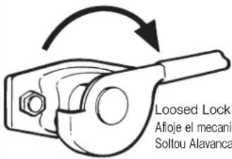
Loosed Lock Lever
Electricity rejection tape
Cinta anti-estática
Inspection before Starting
- The machine is made to be used as a powder spray machine/particle spray machine as delivered, and the only assembly required is the attachment of accessories.
- Inspect all locations for loose screws. Check the chemical tank mount for looseness.
CAUTION
- Loose screws may cause an accident.
- Adjust the length of the pack strap to fit your body.
- When the warning label is peeled off the main unit, buy a new one and attach it.
- Inspect the fuel hose and electric wiring for abnormalities. Also regularly maintain and replace the fuel hose and electric wiring.
1 Shutter lever position is "O".
2 Set connecting rod into "中" setting and tighten lock nut. Adjust as necessary.
3 Secure connecting rod assembly with R-pin.
CAUTION
When connecting Rod is set to link arm. Link arm must be turned right full.
Supplying Premixed Fuel
● Always use premixed fuel. Do not run the machine on gasoline only.
Use the oil specified for 2-stroke engines.
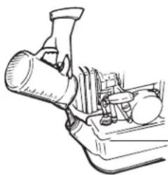
Do not fill beyond the reference line. Fill the oil after stopping the engine. Take care not to spill the fuel. If the fuel is spilled, wipe it off completely.
DANGER
The premixed fuel may catch fire. Fire, such as cigarettes, is strongly prohibited.
Gasoline : Oil
Gasolina : Aceite
Gasolina : Óleo
50:1
natural_image
Technical line drawing of a mechanical device with no visible text or symbols-Reference line
línea de referencia
linha de referência
1 Push up the throttle lever 3 to 4 notches.
2 Operate the priming pump and check the return of premixed fuel via the return pipe.
3 Operate the choke lever.
4 Start the engine by strongly pulling the start rope.
5 Return the choke lever slowly.
6 When the engine does not start Fully open the choke lever and pull the starting rope again. If the engine does not start using this method.
CAUTION
Method of pulling the starting rope.
1. Grip the starting rope with your right hand.
2. Press against the chemical tank with your left hand.
3. Pull the starting rope slowly until you feel resistance.
4. Pull the starting rope in the direction straight from the inlet and outlet of the starter.
5. Do not pull the starting rope all the way out.
6. Keep hold of the starting rope and return it all the way to the original position before letting it go.
- Align the shutter lever with "0".
- Remove the lump and feed in the chemical being careful not to spill it on the outside. When pouring the chemical into the tank, be careful not to spill the chemical on the outside. Only fill the tank with the amount to be sprayed.
- Check the chemical tank cover packing and securely close the cover. If the cover is loose, it may effect the spraying. In addition, the chemicals might spill out and get on you. Use chemicals that do not contain foreign matter, such as dust, lump, and that are dried well.
natural_image
Simple line drawing of a bottle with an ink drop (no text or symbols)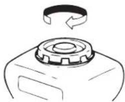
natural_image
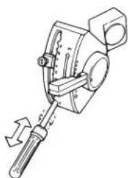
Simple line drawing of a mechanical component with a circular arrow indicating rotation (no text or symbols)- Refer to the [Spray Plan Table] to see how far the shutter must be opened. Move the shutter lever stopper and align it with necessary opening. Refer to [Example Spraying Work] for information regarding the stopper position.
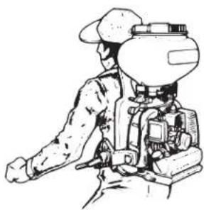
2 Shoulder the machine on your back.
CAUTION
The machine is heavy when filled with chemical. Be careful when handling it.
3 Operate the throttle lever and align it with the discharge nozzle. The lever is operated by pushing lightly to wards the outside.
4 Pull the grip of the shutter lever and bring it to a position that is easy to operate.
5 Raise the shutter lever to begin spraying. Begin spraying by pulling the shutter lever lightly to the inside.
Inicio del rociado
natural_image
Line drawing of a soldier in uniform operating equipment (no text or symbols)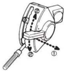
natural_image
Technical line drawing of a mechanical device with a lever and handle (no text or symbols)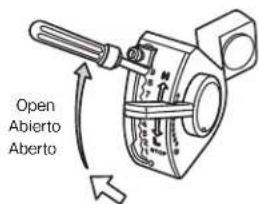
Finishing Spray
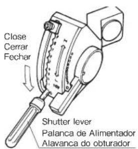
1 Push down the shutter lever and finish spraying.
2 Push and contract the grip of the shutter lever.
Stopping the Engine
1 Pushdown the shutter-lever to the lowest stage and stop spraying.
2 Move the throttle to the lowest stage keeping the shutter closed and then stop the engine.
natural_image
Technical line drawing of a mechanical clamp or tool (no text or symbols)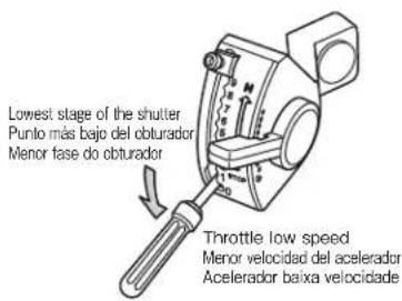
Fertilizer Link position is “多” or “中”.
Duster (Powder) Link position is “多”.
Small Granular Link position is "少".
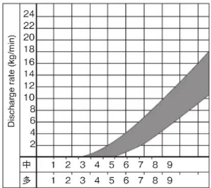
area
| X | Y | |----|------| | 1 | 0.0 | | 2 | 0.5 | | 3 | 1.0 | | 4 | 2.0 | | 5 | 3.5 | | 6 | 5.0 | | 7 | 7.0 | | 8 | 10.0 | | 9 | 15.0 |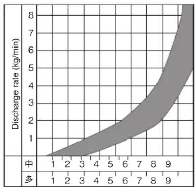
area
| Discharge rate (kg/min) | Value | | ------------------------ | ----- | | 0 | 1 | | 1 | 2 | | 2 | 3 | | 3 | 4 | | 4 | 5 | | 5 | 6 | | 6 | 7 | | 7 | 8 | | 8 | 9 | | 9 | 10 |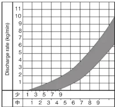
area
| Discharge rate (kg/min) | Value | | ------------------------ | ----- | | 1 | 1 | | 3 | 3 | | 5 | 5 | | 7 | 7 | | 9 | 9 |- Use the preceding graphs as a scale of reference for setting the degree of shutter aperture. Try to blow all fertilizer or seeds continuously, without stopping until the tank goes empty. Don't stop the blowing operation on the way, leaving chemicals in the tank or store the machine with chemicals in the tank, otherwise it will be vulnerable to rust and stain. If closing the shutter with fertilizer or seeds in the tank, lower the lever slowly. If the shutter is suddenly closed or forced to shut, fertilizer or seeds may be caught between the shutter and tank bottom packing, which not only prevents the shutter from closing all the way, but may also causes troubles. When fertilizer or seeds get stuck during operation, raise the shutter one stage upper to increase fan speed.
Cleaning
- Do the same cleaning procedures as stated in the dust blower, but because of fertilizer being highly hygroscopic and corrosive, clear the tank of residual chemicals thoroughly.
Notice on Fertilizer Dispersion
- Use up all the fertilizer in the chemical tank continuously without intermitting dispersion as far as possible.
- When closing the shutter while the fertilizer is in the tank, move the shutter lever down slowly.
- Quick or forced closing of the shutter may cause biting of the fertilizer, resulting in equipment failure.
- When the discharge of fertilizer frequently stops during spraying, remove the clog and then raise the shutter lever one step and increase the spray speed.
- When there is still fertilizer in the chemical tank after the work is finished, recover the fertilizer
Accurate Discharge Calculation Method
● The discharge may differ according to the relative humidity, type of chemical, etc. Use the graph and table as a guideline.
- Accurate discharge can be obtained as follows.
Set the intermediate rod in the shutter arm according to the type of the chemical to be sprayed.
Perform a test spray by setting to the planned shutter opening.
Measure the required number of seconds for the test and calculate by substitution.
Discharge quantity (kg/min)=Input quantity ×60Time for discharge(sec)
● The walking speed can be calculated more accurately by using this value.
CAUTION
● Perform the above method especially for the first spray of a 1kg/10a granule chemical.
● Pay special attention to prevent too much spraying of the chemical.
- When performing dispersion, pay attention to the NOTICE for the chemical or fertilizer to be applied.
Chemical Tank Cleaning
1 Remove the chemical tank. Take out the R-pin and pull out the intermediate rod.
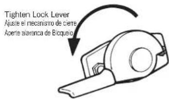
2 Open the tank shutter, remove the chemicals in the tank, and clean the tank. Turn look lever and remove the tank.
3 Take out the disgorge-case and clean and inspect the interior of the blower.
4 Install the chemical tank.
5 The chemical tank shall be loosened in advance.
CAUTION
● Tightening shall be made alternately to hold both sides (Lower than horizontal).
- When fertilizer is sprayed, the shutter may become stuck or metal parts may corrode, therefore, careful cleaning is required.
- If the removed chemical tank is placed on the floor, place it with the cover facing down.
natural_image
Diagram of a mechanical device with an upward arrow indicating motion or force, no text or symbols present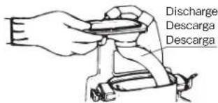
natural_image
Simple line drawing of a mechanical component with a circular arrow indicating rotation (no text or symbols)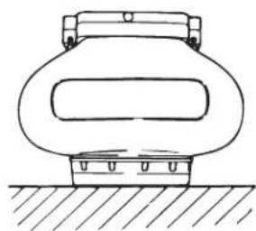
natural_image
Simple line drawing of a cylindrical container with a side port, resting on a surface (no text or symbols)MAINTENANCE
PERIODIC MAINTENANCE CHART
WARNING
- Do not attempt to start or operate a duster that indicates a fuel leak.
● Always remove the spark plug cap from spark plug when servicing the engine to prevent accidental starting.
MANTENIMIENTO
CUADRO DE MANTENIMIENTO PERIODICO
ADVERTENCIA
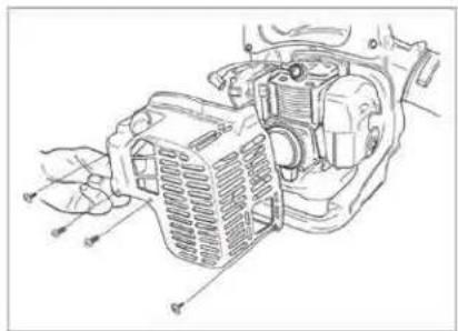
The air filter should be inspected each time the duster is used (or more often with extreme conditions). To inspect, remove the air filter cover and remove the filter from the case. Clean air filter(s) by gently tapping element or cleaning with a suitable solvent the filter should be completely dry before using again.
SPARK PLUG
The spark plug should be removed from the engine and checked after each fifty (50) hours of use. The tips can be cleaned with a stiff brush. Adjust the gap to .024" - .028" (0.6 - 0.7mm) inches (see sketch). Replace the spark plug if it is oil-fouled or damaged.
CAUTION
The correct torque for the spark plug is 95 - 148 in. lbs. (10.7 - 16.6 N·m) Do not over-tighten.
COOLING FINS
Free passage of air flow through the cylinder cooling fins is required to prevent poor engine performance and shortened engine life. Regularly check and clean all debris from the cooling fins. An AUTHORIZED MARUYAMA DEALER should be contacted for this service.
MUFFLER AND EXHAUST PORTS
The muffler should be removed and serviced after each one fifty (50) hours of use. At the same time, the exhaust ports should be cleaned and inspected. An AUTHORIZED MARUYAMA DEALER should be contacted for this service.
FILTRO DE AIRE
natural_image
Line drawing of a mechanical assembly with hands operating a component (no text or symbols)FUEL FILTER
The fuel filter should be cleaned and inspected for damage after each twenty (20) hours of use. The fuel filter is attached to the fuel pick-up tube inside the fuel tank. Loosen the clamp and take out the fuel filter.
To clean the fuel filter, remove it from the fuel tube and wash it with safety solvent. Inspect and clean the fuel tank before re-installing the fuel filter.
Always replace a defective fuel filter.
GENERAL CLEANING AND TIGHTENING
The MARUYAMA duster will provide maximum performance for many hours, if it is maintained properly. Good maintenance includes regular checking of all fasteners for correct tightness, and cleaning the entire machine. Contact an authorized MARUYAMA dealer for additional maintenance suggestions.
SPARK ARRESTER
- Remove the screw from the muffler.
- Take the spark arrester out off the muffler, and then clean by brushing it.
- Return the spark arrester to the muffler.
- Tighten the screw securely.
STORAGE
For long-term storage of the duster, first perform all regular maintenance procedures and needed repairs. Empty the fuel tank. Disconnect the fuel supply line from the carburetor and depress the primer bulb until fuel stops discharging from the fuel-return line. Start the engine and allow it to run until it stops. Pull the starter cord a few times to remove any excess fuel from the engine. Remove the spark plug and insert a small amount of oil into the cylinder. Slowly pull the starter cord and bring the piston to a position closest to the spark plug hole. Re-install the spark plug. Apply a thin coating of oil to all the metal surfaces and store the duster in a dry place.
ALMACENAJE
natural_image
Abstract black and white geometric logo resembling a stylized mountain or wave (no text or symbols)Maruyama U.S., Inc.
3570 Shelby Lane
Denton, TX 76207 U.S.A
Phone 940-383-7400
Fax 940-383-7466
www.maruyama-us.com
P/N. 275711-00 15.03 TAP/Q
- FOREWORD
- ⚠ Warning label
- ADVERTENCIA
- General
- Seguridad
- ASSEMBLY INSTRUCTIONS
- Finalidad de uso
- Shutter Lever
- Shutter Arm
- Electric Charge Prevention Equipment
- Mecanismo de traba
- Inspection before Starting
- CAUTION
- Supplying Premixed Fuel
- DANGER
- The machine is heavy when filled with chemical. Be careful when handling it.
- Inicio del rociado
- Finishing Spray
- Stopping the Engine
- Cleaning
- Notice on Fertilizer Dispersion
- Accurate Discharge Calculation Method
- Chemical Tank Cleaning
- MAINTENANCE
- PERIODIC MAINTENANCE CHART
- WARNING
- MANTENIMIENTO
- CUADRO DE MANTENIMIENTO PERIODICO
- SPARK PLUG
- COOLING FINS
- MUFFLER AND EXHAUST PORTS
- FILTRO DE AIRE
- FUEL FILTER
- GENERAL CLEANING AND TIGHTENING
- SPARK ARRESTER
- STORAGE
- ALMACENAJE
Brand : Maruyama
Model : MD3015
Category : Uncategorized