Alzare Single - Uncategorized Arozzi - Free user manual and instructions
Find the device manual for free Alzare Single Arozzi in PDF.


| Product Type | Single Monitor Arm |
| Brand | Arozzi |
| Model | Alzare Single |
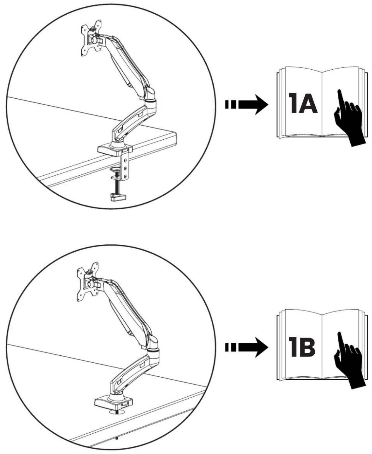
| Mounting Options | Clamp or Grommet |
| VESA Compatibility | 75x75mm, 100x100mm |
| Weight Capacity | Up to 8 kg (17.6 lbs) |
| Material | Aluminum alloy, steel |
| Color | Black |
| Height Adjustment | Gas spring, 0-30 cm range |
| Tilt Range | -90° to +90° |
| Swivel Range | ±180° |
| Rotation Range | 360° (landscape/portrait) |
| Cable Management | Integrated clips |
| Desk Thickness | Clamp: 10-50 mm; Grommet: up to 50 mm hole |
| Installation Tools | Included hex key |
| Warranty | 2 years |
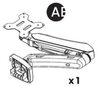
| Package Contents | Arm, clamp, grommet base, screws, manual |
| Net Weight | 2.5 kg (5.5 lbs) |
| Gross Weight | 3.0 kg (6.6 lbs) |
| Dimensions (Arm) | 50 x 12 x 8 cm |
| Cleaning Instructions | Wipe with a soft dry cloth; avoid solvents |
Frequently Asked Questions - Alzare Single Arozzi
User questions about Alzare Single Arozzi
0 question about this device. Answer the ones you know or ask your own.
Ask a new question about this device
Download the instructions for your Uncategorized in PDF format for free! Find your manual Alzare Single - Arozzi and take your electronic device back in hand. On this page are published all the documents necessary for the use of your device. Alzare Single by Arozzi.
USER MANUAL Alzare Single Arozzi
natural_image
Line drawing of a robotic arm with articulated joints and mounting base (no text or symbols)
youtube.com/@ArozziSupport
EU: arozzi.se/support/
US: arozzi.com/support/
Elsewhere: arozzi.se/support/
natural_image
Technical line drawing of a mechanical device with no visible text or symbols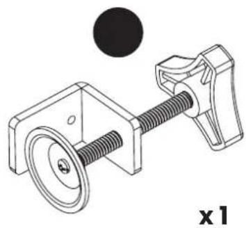
natural_image
Mechanical assembly diagram showing a pulley and lever mechanism (no text or symbols)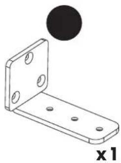
natural_image
Technical illustration of a metal bracket with mounting holes and a circular hole (no text or symbols)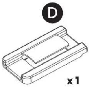
natural_image
Technical line drawing of a mechanical component with a circular indicator labeled 'D' and 'x1' (no text or symbols on the diagram itself)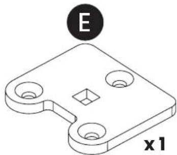
natural_image
Isometric technical drawing of a mechanical part with circular holes and a square hole, labeled 'E' and 'x1' (no text or symbols on the object itself)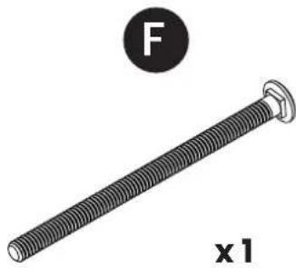
natural_image
Illustration of a threaded bolt with a circular label containing letter F and the label 'x1' below (no text or symbols on the bolt itself)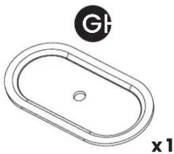
natural_image
Technical line drawing of an oval-shaped sink with a central hole and a circular symbol labeled 'G' (no text or symbols beyond the label)
natural_image
Technical line drawing of a mechanical component with threaded end and flange (no text or symbols)
natural_image
Technical illustration of a screw with a black circular head and hexagonal end (no text or symbols)
natural_image
Simple line drawing of a folded paper or sheet with a circular logo containing the letters JK and x1 (no text or symbols on the sheets)
natural_image
Mechanical component with threaded shaft and circular head, labeled 'x 4' (no text or symbols on the component itself)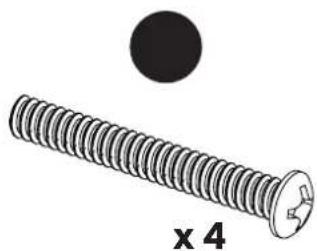
natural_image
Close-up of a black screw with a circular head and a cross mark, labeled 'x 4' below (no other text or symbols)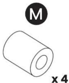
natural_image
Simple line drawing of a cylindrical object with a black circle labeled 'M' and 'x 4' below it (no text or symbols on the object itself)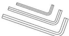
natural_image
Pure line drawing of four identical L-shaped metal bars (no text or symbols)1A
1.1
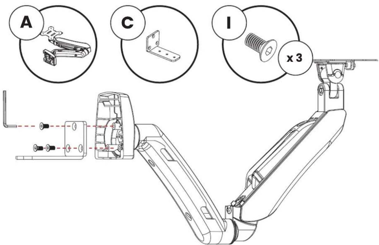
1.2
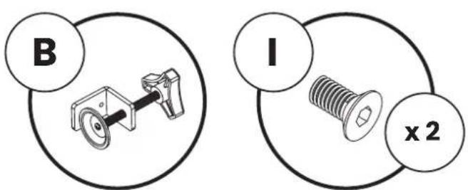
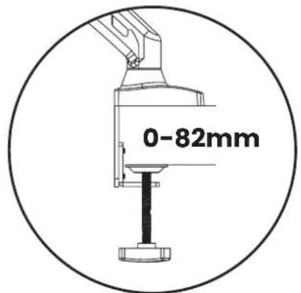
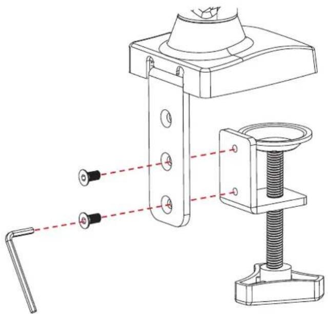
natural_image
Technical line drawing of a mechanical clamp assembly with mounting bracket and spring (no text or symbols)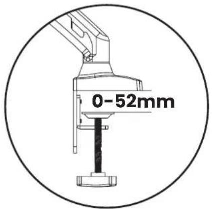
1.3
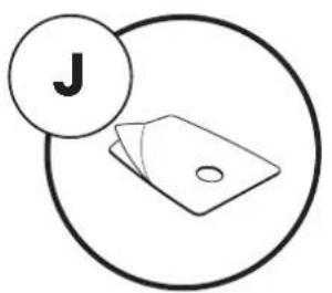
natural_image
Simple line drawing of a folder with a letter 'J' and a circular outline (no text or symbols beyond the label)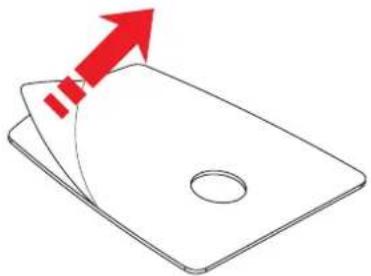
natural_image
Simple line drawing of a card with a red arrow pointing upward (no text or symbols)1.4
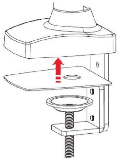
natural_image
Technical line drawing of a mechanical device with a central component and red arrow indicating upward motion (no text or symbols)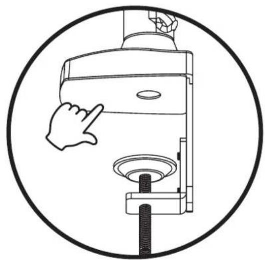
natural_image
Line drawing of a hand pressing down on a mechanical device inside a circle (no text or symbols)1.5
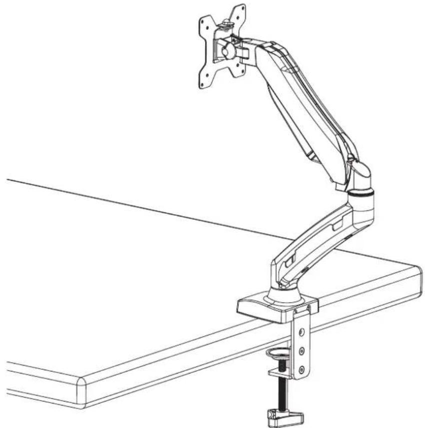
natural_image
Line drawing of a mechanical arm mounted on a platform, showing articulated joints and mounting bracket (no text or symbols)1.6
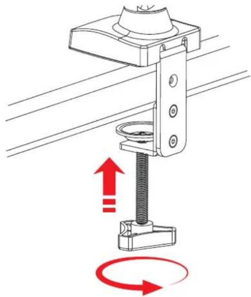
natural_image
Mechanical assembly diagram showing a spring-loaded clamp with red directional arrows indicating rotational motion (no text or symbols)1.7
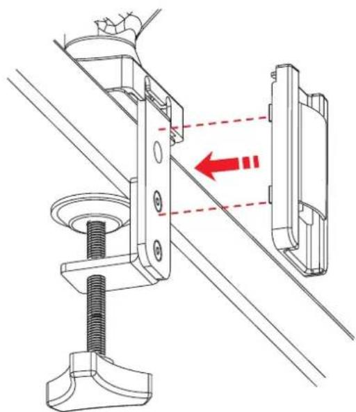
natural_image
Technical diagram of a mechanical clamp assembly with red arrows indicating motion or force direction (no text or symbols present)1.8

1B
1.1
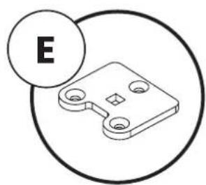
natural_image
Simple line drawing of a mechanical component with circular outline and letter E label (no text or symbols on the object itself)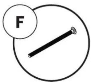
natural_image
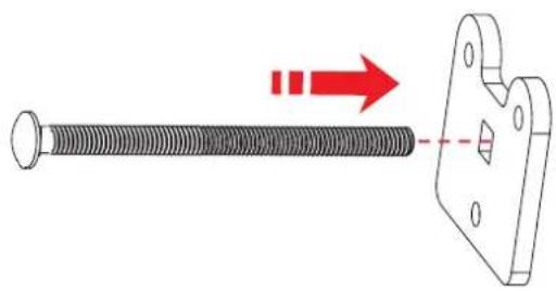
Diagram showing a threaded bolt being inserted into a bracket with a red arrow indicating direction (no text or symbols present)1.2
1.3
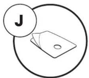
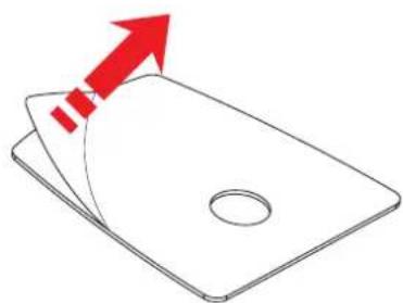
natural_image
Simple line drawing of a folded paper or sheet with a red arrow pointing upward (no text or symbols)1.4
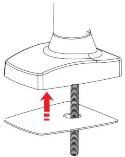
natural_image
Technical diagram of a mechanical press or clamping device with a red upward arrow indicating motion (no text or symbols present)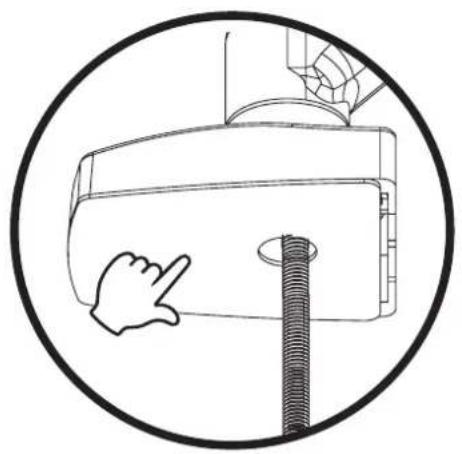
natural_image
Simple line drawing of a hand pointing at a screw and a cylindrical component inside a circular frame (no text or symbols)1.5
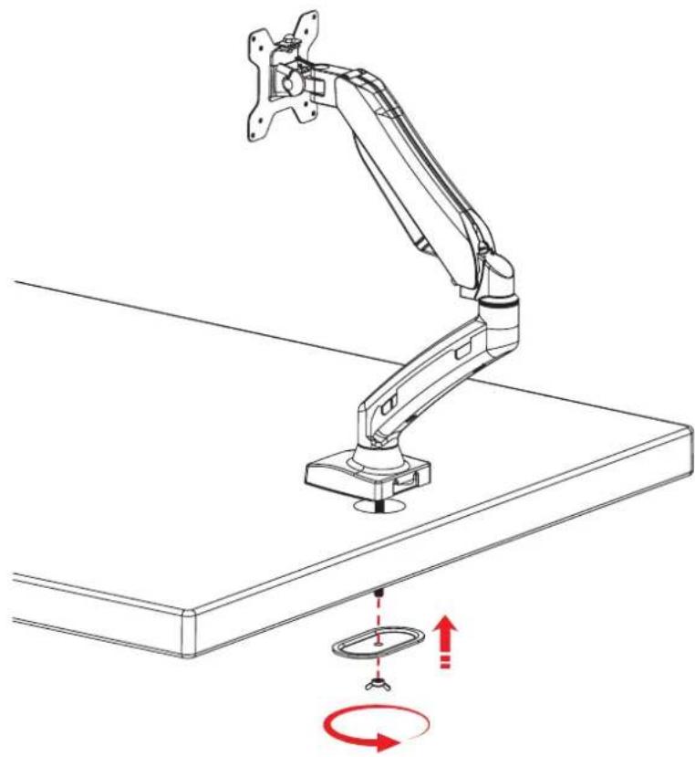
natural_image
Line drawing of a robotic arm mounted on a desk with red motion indicators (no text or symbols)1.6

2
2.1
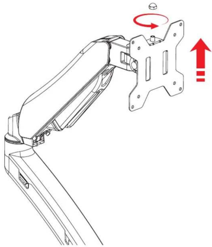
natural_image
Technical line drawing of a robotic arm with rotating components and red directional arrows indicating motion (no text or symbols)2.2
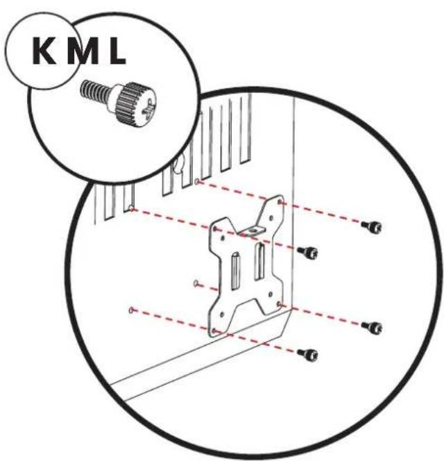
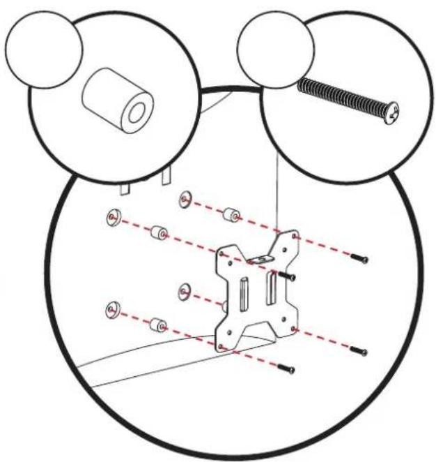
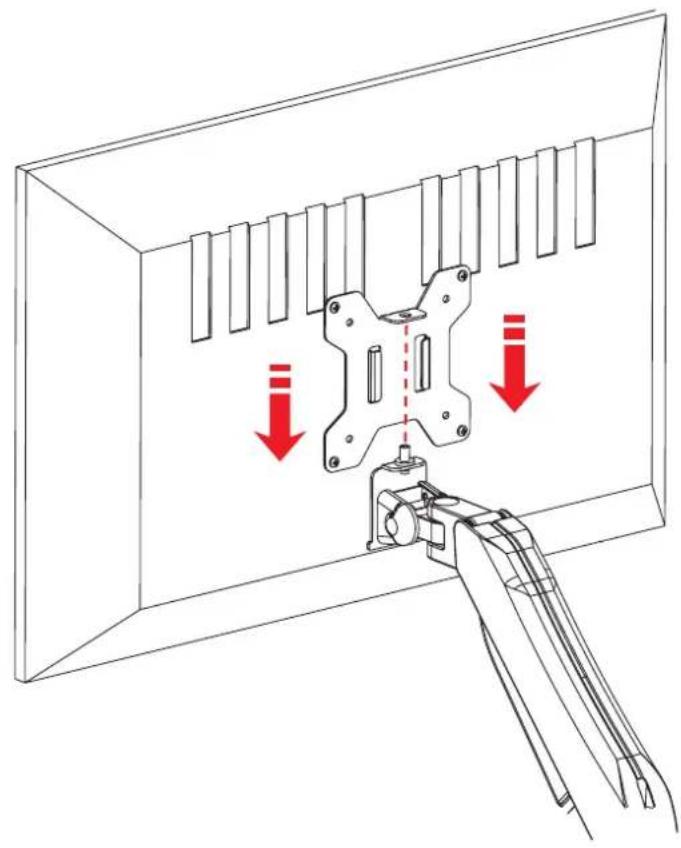
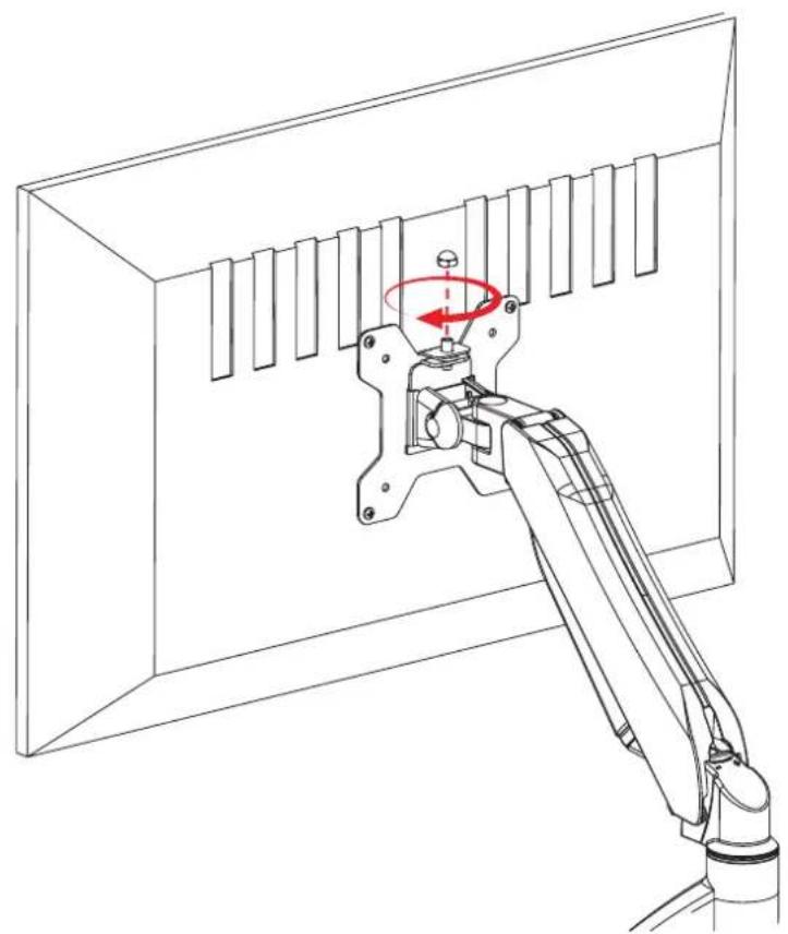
Flat Back Monitor Curved Or Recessed Back
Monitor
2.3
natural_image
Technical line drawing of a mechanical clamp or bracket assembly with red arrows indicating downward motion (no text or symbols present)2.4
natural_image
Technical line drawing of a mechanical assembly with a red rotation arrow indicating rotational motion (no text or symbols)3
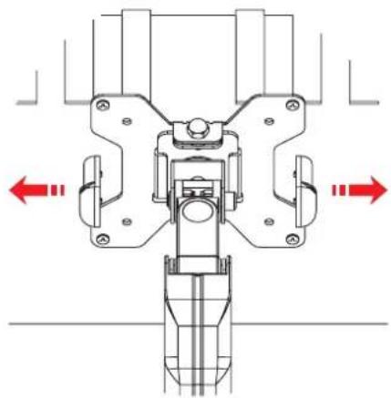
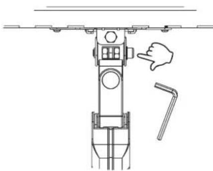
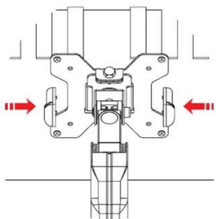
Adjusting the tilt angle position

If your monitor tilts forward, adjust the tilt angle position by tightening the screw under the plastic caps.
3.1
natural_image
Mechanical assembly diagram showing a central component with two red directional arrows indicating movement or force directions (no text or symbols present)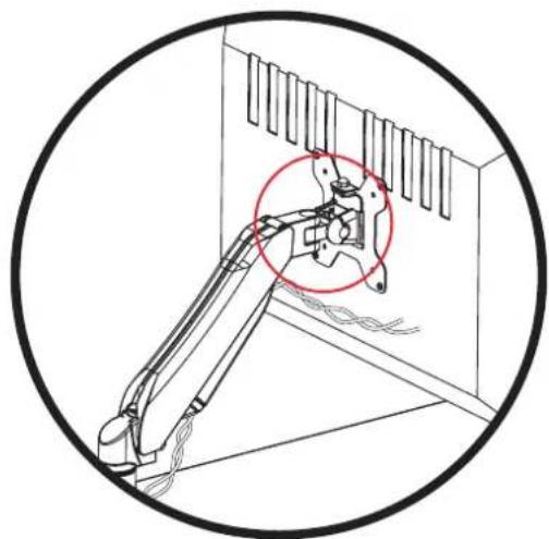
natural_image
Technical line drawing of a mechanical arm assembly inside a room, showing structural components and a red circle highlighting a specific part (no text or symbols present)3.2
natural_image
Technical line drawing of a mechanical device with a hand pointing to a component (no text or symbols)3.3
natural_image
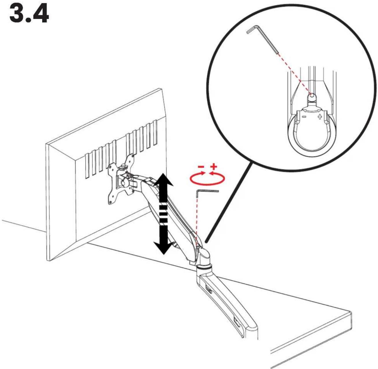
Mechanical assembly diagram showing a valve mechanism with red directional arrows indicating motion (no text or labels)Adjusting the torque of the gas spring
Adjust the torque of the gas spring according to the weight of your monitor.
If your monitor cannot stay in the lower position, turn the screw clockwise (-).
If your monitor cannot stay in the higher position, turn the screw counterclockwise (+).
Keep turning until the monitor can be raised and lowered easily.
3.4
4
4.1
natural_image
Technical line drawing of a mechanical component with a red arrow indicating downward motion (no text or symbols)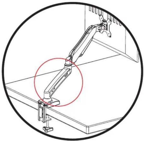
natural_image
Technical line drawing of a mechanical arm assembly inside a circular frame, showing no text or symbols.4.2
natural_image
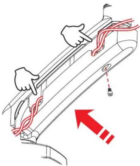
Diagram of hands installing red cables on a device panel, with a red upward arrow indicating motion (no text or symbols present)4.3
natural_image
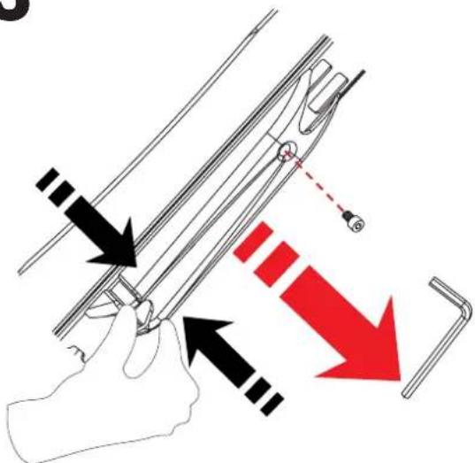
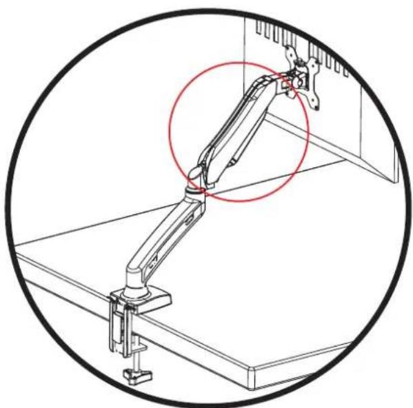
Technical line drawing of a mechanical arm assembly with a red circle highlighting a specific joint (no text or symbols present)4.4
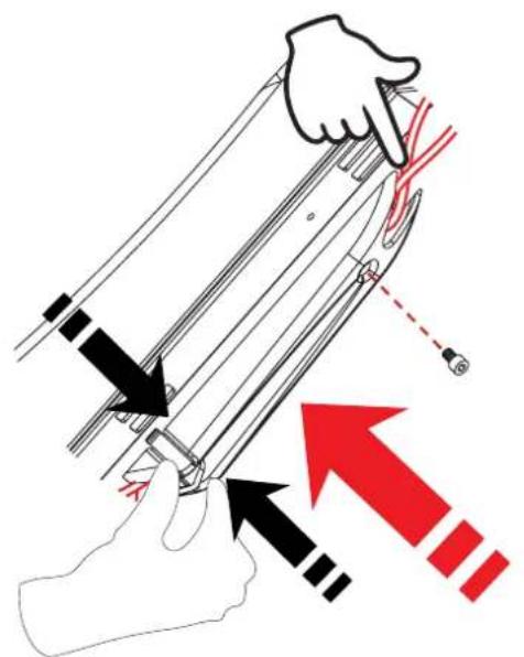
4.5
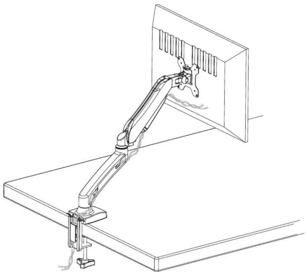
natural_image
Line drawing of a mechanical arm mounted on a desk, showing articulated joints and wiring (no text or symbols)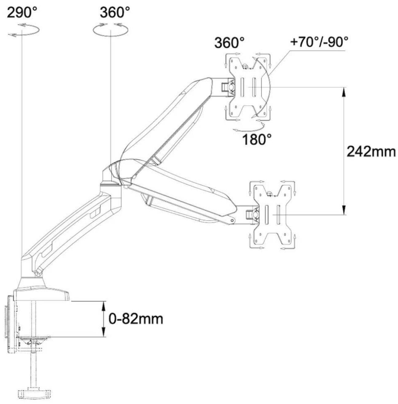
Brand : Arozzi
Model : Alzare Single
Category : Uncategorized