A711 - Uncategorized ACTi - Free user manual and instructions
Find the device manual for free A711 ACTi in PDF.


| Product Type | Network Camera |
| Model | A711 |
| Brand | ACTi |
| Image Sensor | 1/2.8" Progressive Scan CMOS |
| Resolution | 1920x1080 (Full HD) |
| Frame Rate | 30 fps |
| Lens Type | Fixed focal, f=2.8mm |
| Field of View | 95° horizontal |
| Minimum Illumination | 0.05 lux (color) |
| Day/Night | Mechanical IR cut filter |
| Compression | H.264, MJPEG |
| Network Interface | 10/100 Ethernet (RJ-45) |
| Power Supply | PoE (IEEE 802.3af) |
| Power Consumption | 5W max |
| Dimensions (W x H x D) | 70 x 60 x 120 mm |
| Weight | 350 g |
| Housing Material | Aluminum |
| Ingress Protection | IP66 |
| Operating Temperature | -10°C to 50°C |
| Audio | Built-in microphone, one-way audio |
| Storage | MicroSD card slot (up to 128GB) |
| Warranty | 2 years limited |
| Included Accessories | Mounting kit, quick start guide |
Frequently Asked Questions - A711 ACTi
User questions about A711 ACTi
0 question about this device. Answer the ones you know or ask your own.
Ask a new question about this device
Download the instructions for your Uncategorized in PDF format for free! Find your manual A711 - ACTi and take your electronic device back in hand. On this page are published all the documents necessary for the use of your device. A711 by ACTi.
USER MANUAL A711 ACTi
A711 Outdoor Hemispheric Dome Quick Installation Guide
The Quick Guide is for quick installing and connecting the Outdoor Hemispheric Dome Camera. For more details, please refer to the User's Manual of the camera.
Installation Notices
- This camera must be installed by qualified personnel and the installation should conform to all local codes.
- Do not replace batteries of the camera. Risk of explosion may occur if the battery is replaced by an incorrect type.
- Leaving a camera in an extremely high temperature surrounding environment can result in an explosion or the leakage of flammable liquid or gas.
- Camera subjected to extremely low air pressure may result in an explosion or the leakage of flammable liquid or gas.
- Use only power supply and other accessories recommended by the manufacturer.
- The power cord of the adapter should be connected to a socket-outlet with earthing connection.
Camera Overview
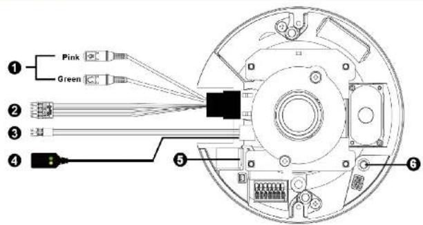
| No. | Connector | Pin | Definition | Remarks |
| 1 | Audio I/O | Pink | Audio In (Line In) | Two-way audio transmission |
| Green | Audio Out (Line Out) | |||
| 2 | Alarm I/O(4-Pin Terminal Block) | 1 | Alarm In – | Alarm connection* Do NOT connect external powersupply to the alarm I/O connector ofthe camera. |
| 2 | Alarm In + | |||
| 3 | Alarm Out – | |||
| 4 | Alarm Out + | |||
| 3 | Power (DC 12V)(2-Pin Terminal Block) | Black | DC 12V – | Power connection |
| Red | DC 12V + | |||
| 4 | RJ-45 | - | For network and PoE connections | |
| 5 | microSD Card Slot | - | Insert the microSD card into the card slot to store videos and snapshots.Do not remove the microSD card when the camera is powered on. | |
| 6 | Reset Button | - | Press the button with a proper tool for at least 20 seconds to restore the system. | |

NOTE: It is not recommended to record with the microSD card for 24/7 continuously, as it may not be able to support long term continuous data read/write. Please contact the manufacturer of the microSD card for information regarding the reliability and the life expectancy.
Camera Cabling
Please follow the instructions below for cable connections.
Power Connection
Please use a DC 12V power adaptor and plug it to the camera and the power outlet. Alternatively, users can use an Ethernet cable and connect it to the RJ-45 connector of the camera and a Power Sourcing Equipment (PSE) switch.

NOTE: If the device is powered over Ethernet, make sure the PSE is connected to the network.
Ethernet Cable Connection
Connect one end of the Ethernet cable to the RJ-45 connector of the camera, and plug the other end of the cable to the network switch or PC.

NOTE: In some cases, Ethernet crossover cable might be needed when connecting the camera directly to the PC.

NOTE: Check the status of the link indicator and activity indicator LEDs. If the LEDs are unlit, please check the LAN connection.
Green Power LED : Lights up when the camera is powered up.
Orange Network LED : (1) flashes when data is being transmitted over network,
(2) lights up for good network connection.

NOTE: The ITE is to be connected only to PoE networks without routing to the outside plant or equivalent description.
Before Login to the Camera
A client program will be automatically installed to the PC when connecting to the camera. Before logging in to the camera, ensure downloading the ActiveX control is allowed by either changing the ActiveX controls and plug-ins or setting Internet's security level to default.
| ActiveX Controls and Plug-ins Settings | Internet Security Level |
| Step 1: Start the Internet Explorer (IE).Step 2: Selectfrom the main menu of the browser, Then click on. | Step 1: Start the Internet Explorer (IE).Step 2: Selectfrom the main menu of the browser, Then click on. |
| Step 3: Click on thetab and select, and click onto change ActiveX settings.Step 4: Set "ActiveX controls and plug-ins" items toor. | Step 3: Click on thetab and select.Step 4: Down the page, clickand click onto confirm the setting. Close the browser window, and open a new one later for accessing the IP camera. |
Camera Login
The default IP address of the camera is: 192.168.0.100 Therefore, to access the camera for the first time, please set the IP address of the PC as: 192.168.0.XXX; for example:
IP Address: 192.168.0.99
Subnet Mask: 255.255.255.0
Login ID and Password
- Type in corresponding camera IP address into the URL field on the web browser and hit "Enter".
- For initial login, use the default username, "admin", and then setup the password. Follow the on-screen instructions to do so. This username and password will be used for succeeding login. Note that the username and password are case sensitive.
Default Username: admin
Password: (user must setup first)
Install the ActiveX Control
• After connecting to the camera, the request for installing the ActiveX control will appear just below the URL bar.
- Right click on the information bar, and then click on
- In the pop-up security warning window, click on
- Click on
Browser-based Viewer
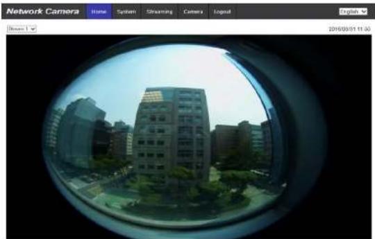
The main page of the IP camera user interface is shown as the figure below. Actual features may vary depending on model.
natural_image
View through a circular window showing an urban residential building, captured in fisheye (no text or symbols visible)Stream 1: H264 bbitrate: \$144 kbps low compression, high quality
Stream 2: H264 bbitrate: 4096 kbps
Stream 3: H264 bbitrate: 3048 kbps miniella compression, miniella quality
Stream 4: H264 bbitrate: 2048 kbps miniella compression, miniella quality.
A711
Outdoor Hemispheric Dome Camera Quick Installation Guide
- A711 Outdoor Hemispheric Dome Quick Installation Guide
- Installation Notices
- Camera Cabling
- Power Connection
- Ethernet Cable Connection
- Before Login to the Camera
- Camera Login
- Login ID and Password
- Install the ActiveX Control
- Browser-based Viewer
- Outdoor Hemispheric Dome Camera Quick Installation Guide
Brand : ACTi
Model : A711
Category : Uncategorized