CA2600 - Audio software Cherry Audio - Free user manual and instructions
Find the device manual for free CA2600 Cherry Audio in PDF.


| Product Type | Software Synthesizer (Virtual Analog Emulation) |
| Brand | Cherry Audio |
| Model | CA2600 |
| Platform Support | Windows (7 or later), macOS (10.9 or later) |
| Plugin Formats | VST2, VST3, AU, AAX (64-bit) |
| Standalone Operation | Yes |
| Minimum RAM | 4 GB |
| Minimum CPU | 2 GHz multi-core |
| Disk Space Required | 500 MB |
| Audio Engine | High-precision virtual analog (zero-delay feedback) |
| Polyphony | Up to 8 voices (CPU dependent) |
| Main Features | Dual VCO, Multi-mode filter, Envelope generators, LFO, Spring reverb, Patch panel emulation |
| Presets | Over 250 factory presets |
| Installation Method | Download installer from manufacturer website |
| License Type | Permanent (no subscription), single user |
| Customer Support | Online knowledge base, email, forum |
| Documentation | PDF manual included (64 pages) |
| Safety | No physical safety concerns; ensure system meets requirements |
| Maintenance | Update to latest version via website; no hardware cleaning needed |
| Spare Parts / Repairability | Not applicable (software); reinstall if damaged |
Frequently Asked Questions - CA2600 Cherry Audio
User questions about CA2600 Cherry Audio
0 question about this device. Answer the ones you know or ask your own.
Ask a new question about this device
Download the instructions for your Audio software in PDF format for free! Find your manual CA2600 - Cherry Audio and take your electronic device back in hand. On this page are published all the documents necessary for the use of your device. CA2600 by Cherry Audio.
USER MANUAL CA2600 Cherry Audio
The Cherry Audio CA2600 is a powerful, self-contained duophonic synthesizer inspired by the classic ARP 2600. Every aspect of the original, from the quirky oscillator waves to the powerful ladder filter was modeled with tremendous precision. And although it features very similar functionality,
we've added numerous updates to increase its flexibility and usefulness. Most notably, we've added distortion, delay, and reverb effects - instead of being "tacked-on" like most softsynth effects, these are fully integrated into the user interface with CV control of almost every parameter - we think you'll enjoy them!
CA2600 features semi-normalled audio and modulation paths for modular synth-style flexibility, but like the original ARP 2600, the normalled connections allow rapid sound creation without the use of patch cables. Incidentally, CA2600 uses the same highly refined and super-fast patching system as its big brother, Voltage Modular, making routing, moving, and multing cables a pleasure.
The number-one design goal was to place everything immediately in front of the user for an unprecedented hands-on, "everything right in front of you, right now!" vintage synthesis experience. We think you'll find CA2600 to be the best 2600 emulation ever created, and hope you enjoy scaring the neighbor's dog with it as much as we have!
Pre-Purchase Demo Mode
If you haven't purchased the full version of CA2600, it will run in demo mode. All functions will work, but inharmonic tones will occasionally sound (the LED next to Demo in the top toolbar will illuminate when the ugly tones are sounding). We've also added a handy button to make purchasing easy, so you've got no excuse! As you might expect, all this demo nonsense disappears once CA2600 is purchased.
Technical Assistance
Cherry Audio's unique online store and automatic updating should make operation a smooth experience, but if you run into any issues or have questions, you can discuss issues online at the Cherry Audio forums at:
https://forums.cherryaudio.com/viewforum.php?f=39
... or you can communicate directly with our surly and grumpy outgoing and friendly tech support staff at:
https://cherryaudio.kayako.com/
About This Manual
Each of CA2600's sections is explained in the following chapters. Instead of going across the panel, we've arranged the chapters in the order of signal flow (more or less). In other words, oscillators>filters>amplifiers, etc. If you're not familiar with modular synthesizers, we strongly recommend
reading the Semi-Normalled Patching section, because it's really important to understand how CA2600 works.
Terminology
The 2600 uses standard analog synthesis building blocks such as oscillators, filters, amplifiers, etc. The full name for an oscillator would be a "voltage controlled oscillator," which often is abbreviated to "VCO," for example. The following table shows full names and abbreviations of CA2600's components:
FULL NAME ABBREVIATION
| voltage-controlled oscillator VCO |
| voltage-controlled filter VCF |
| voltage-controlled amplifier VCA |
| low-frequency oscillator LFO |
| sample & hold S&H |
| envelope generator EG |
| attack, decay, sustain, release ADSR |
| attack, release AR |
| Twisted Sister TS |
| Blue Öyster Cult BOC |
Top Toolbar and Preset Browser

The purple strip at the top of the CA2600 interface is where you'll load, save, and create sound presets. It also contains utility functions such as undo, redo, UI zoom and Focus controls, under-the-hood settings, and more. Let's go over them:
New- Opens a new blank patch preset. By default, if an unsaved patch is currently open or you've modified an existing saved patch, a dialog asks if you'd like to save the patch in its current state. This greatly reduces the possibility of losing an edited unsaved patch. (This can be disabled by disabling the checkbox Settings>Interface>"Ask To Save Presets.")
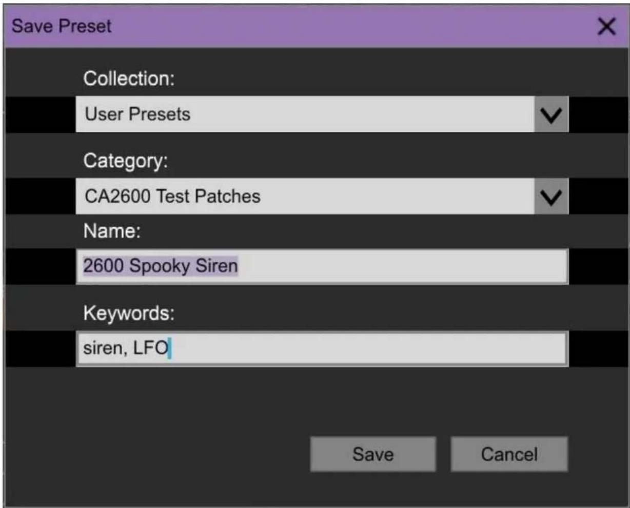
Save- Use this to save patches. There are a couple of levels of hierarchy:
- Collection- This is the top level of organization, and contains entire “sets” of presets. The CA2600 Presets are the main included collection. We also include a User Presets Collection for storing your own presets, but you’re free to create your own collections. To create a new collections, click in the Collection text field (where it says User Presets above) and type a name. User-created sounds can be freely saved to any collection; we like to keep ‘em separated for organizational purposes.
- Categories- Within each Collection are a number of sound categories. As with collections, you're free to create as many categories as you like. To create a category, click in the Category text field of the Save dialog window and type a new category name.
- Patch- A patch is an individual sound. To save a patch, simply type the name in the Name field and click Save.
- Keywords- Descriptive words such as "huge," "noisy," "poly," etc., can be added to patches to make them appear when terms are typed in the Search field. Use commas to separate multiple keywords entries.
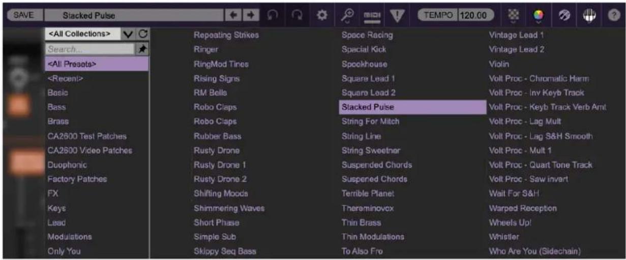
Browsing Patches- Patches can be browsed by clicking the
Clicking on the left-side categories narrows down which patches are displayed.
will show presets from all collections and categories. displays recently used presets.
- Refresh- This is the circular arrow button to the right of the downward arrow; clicking this checks the Cherry Audio server for new or updated presets.
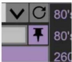
Pin - Clicking the push-pin icon locks the patch selection list open, allowing fast and easy browsing and auditioning of patches. Click the icon again to disable pin mode. when in pin mode, the up and down arrow keys can be used to select patches.
Preset- Step Back/Forward Arrows- These step to the previous or next preset.macOS [⌘+left/right arrow key] or Windows [CTRL+left/right arrow key] will navigate through presets back and forth in the currently selected collection/category.
Undo/Redo- These circular arrows will undo or redo the last action. It remembers many steps, so if you really loused something up, keep on clickin'...
Settings- This is where user preferences for user interface, audio interfaces, user account, and more are configured. See the Settings section for full information.
Importing Presets with drag-and-drop
Presets can be imported singly or en masse (as a single compressed ZIP file) simply by dragging and dropping from the desktop anywhere on the user interface.
If a single .*preset file is dragged and dropped, the sound is immediately loaded and the standard Save Preset dialog appears; this lets you save the sound to the instrument's preset browser. Note that you don't have to save the sound to preset browser; if you just want to hear and play the sound, click the Cancel button in the Save Preset dialog - the sound will still be loaded.
Compressed zip files containing multiple sounds can also be drag and dropped onto the UI. This works the same as with single sounds, but instead of the Save Preset dialog, you'll see the Import Preset Collection dialog. The presets will be added as a new collection and available in the categories for which they were tagged.
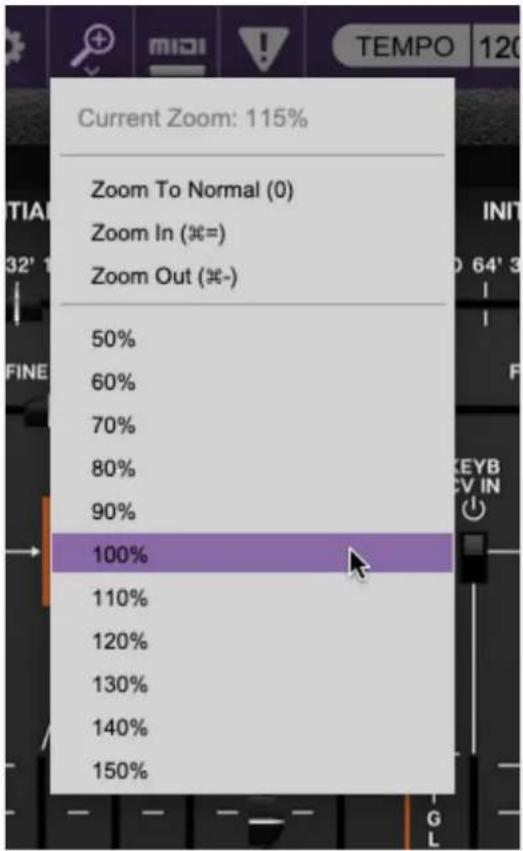
Zoom Magnifying Glass- Click to resize the CA2600 interface. Selecting 100% returns the user interface to native size.
MIDI Tab-Opens the MIDI controllers tab for configuring internal and hardware MIDI controls. See the MIDI Controllers Setup and MIDI Tab
section for full information.
! (MIDI Panic) - Click to send an all-notes-off message in case of, "why won't this thing stop making noise?!?" stuck-note incidents. If that doesn't shut it up, check the Initial Gain slider in the Voltage Controlled Amplifiersection (toward the right, near the top). If that doesn't work, try turning down the Mast Vol at the top right. If THAT doesn't work... try kicking it?
Tempo(Standalone Version Only)- Displays CA2600's current internal tempo setting. CA2600's internal tempo affects the Sample & Hold, Low Frequency Oscillator, and Delay sections when their corresponding Sync buttons are toggled. The tempo setting can be changed by moving the mouse up and down anywhere in the tempo section, or by double-clicking the number and entering the desired BPM value.
The tempo display only appears in the standalone version of CA2600. VST, AU, and AAX plug-in versions receive tempo data from their host DAW app.
Cable Transparency- Clicking the checkerboard icon displays the cable transparency slider. Slide this to the left for more transparent cables, or to the right for more opaque cables.
Cable Color Select- Click this to select the global cable color, i.e. the color of any newly patched cable. Clicking Random randomly chooses a color for each new cable.
Show/Hide Cables- Clicking this hides or shows all cables. It has no effect on sounds, and its status does not save with patches. Cables can also be shown or hidden using the key shortcuts [CONTROL-D] (PC) or [✗-D] (Mac).
Special Cool Cable Color Select Feature- The color of any existing cable can be changed by right-clicking in jack area. Right-clicking on a jack that doesn't have a cable plugged in will change the global cable color (i.e. the same as changing the color with the toolbar button).
natural_image
Abstract geometric pattern with vertical stripes inside a circle on a dark purple background (no text or symbols)QWERTY Musical Typing Keyboard Opens an onscreen keyboard allowing a standard QWERTY computer keyboard to be used for playing music notes. For
more information, see QWERTY Musical Typing Keyboard (MTK) section.

Help - Clicking this launches your web browser and opens the help document you're currently reading. This some serious circular logic when you think about it.
CA2600 logo (lower-right corner, it's huge, how could you miss it?)- This isn't really in the top toolbar, but clicking this displays "about" information, and shows the version number and current registered user ID.
Focus Button
Since the original 2600 is beastly large, and maybe your computer display isn't, the UI can potentially be hard to see. With this in mind, the Focus button conveniently blows up the user interface to roughly twice its normal size within the current window size. Unlike the Zoom "magnifying glass" function, Focus doesn't affect the current window size. By default, the patch panel section fills the current window, but the view can be scrolled vertically and horizontally with a mouse wheel, track pad, or Apple Mighty Mouse finger-scrolling. Or if you're the last person on earth still using a single-button mouse, scroll bars will appear at the window edges when in Focus mode. (Drop us a line from that hotmail.com email account, umkay?)
Using Focus mode couldn't be easier - just click the Focus button the top menu bar. To return to standard view, clickReset. There's also a superfast key shortcut - on Mac, hold the Ⓧ [COMMAND] key and click the mouse; in Windows, hold the [OPTION] key and click the mouse. Focus can be reset with the same key shortcuts.
Preset List Right-Click Functions
| Bad Sp | Show File |
| Band To | Show In Original Category |
| Basic In | Favorite |
| Basic P | Delete |
| Basic P | Restore Factory Preset |
| Basic P | Restore All Factory Presets From Collection 'CA2600 Presets' |
| Basic P | Restore All From Factory |
| Basic Saw | Savonide Rial |
| Basic Saw Filter Sweep | Cello Section |
Show File- This displays the selected preset in the Mac or Windows folder containing it. This is useful for backing up or sending a preset file to another user.
Show In Original Category- Selects the preset within its category, i.e. the category will highlight in the left preset menu. The Show In Original Category command only displays if the preset was selected within the
Favorites- Favorited presets will show in when the
Delete- Deletes the selected preset.
Restore Factory Preset- If one of the factory (i.e. not user) patches is edited and saved, selecting this command restores the patch to its unaltered "factory" setting. This menu will be grayed-out for user bank patches.
Restore All Factory Presets From 'CA2600 Presets'- If any patches from the "factory" CA2600 bank are edited and saved, selecting this command restores all of them to their unaltered "factory" setting.
Restore All From Factory- If any patches from the "factory" banks are edited and saved, selecting this command restores all of them to their unaltered "factory" setting. At the time of writing, the CA2600 bank mentioned above is the only factory bank, so this function and the Restore All Factory Presets From 'CA2600 Presets'above have the same effect.
flowchart
graph TD
    A["FM CONTROL"] --> B["KYBD"]
    A --> C["S/H"]
    A --> D["A/SR"]
    A --> E["VCO 2"]
    F["PWM INITIAL"] --> G["LFO"]
    H["FM CONTROL"] --> I["KYBD"]
    H --> J["S/H"]
    H --> K["A/SR"]
    H --> L["VCO 1"]
    M["PWM INITIAL"] --> N["LFO"]
Semi-Normalled Patching
If you've worked with patch bays in recording studios, you may be familiar with the concept of semi-normalled connections. This means that certain connections are invisibly patched by default if no cable is plugged into a jack, but plugging a cable into the jack interrupts the "normalled" signal flow and replaces it with the patched cable. The adjacent orange boxes indicate the default signal source if nothing is plugged into the the jack. If an audio or control signal is plugged into the jack, the normalled source is overridden and replaced with the the patched cable.
Almost all normalled inputs have an attenuator slider either above or next to them. This adjusts the amount of the normalled signal or currently patched cable.
One notable exception are the Oscillator Kybd FM Control input jacks - the slider above controls controls keyboard glide amount, or adds glide to incoming CV signals plugged into the jack. Losing the input attenuator for this input isn't a big deal, because you can always use any of the three remaining FM control inputs, but we'll further explain this in the Voltage Controlled Oscillators section.
To Cable, or Not to Cable?
Because of its extensive and logically arranged normalled connections, CA2600 is a 100% usable synthesizer without ever using patch cables. But using patch cables reveals a world of flexibility, making it just as flexible as any modular synthesizer. As a result, you truly get the best of both worlds. And even if you're an experienced modular user, the numerous normalled connections make sound creation super fast and fun.
It should go without saying that we're a bunch of hardcore synthesizer nerds around these parts, so we encourage you to take advantage of the power and creativity of patch cables.
Using Cables
Basic use of cables is super easy, but since CA2600 utilizes the same highly developed cabling system used in its big brother, Voltage Modular, it's got a number of tricks up its sleeve that aren't immediately obvious.
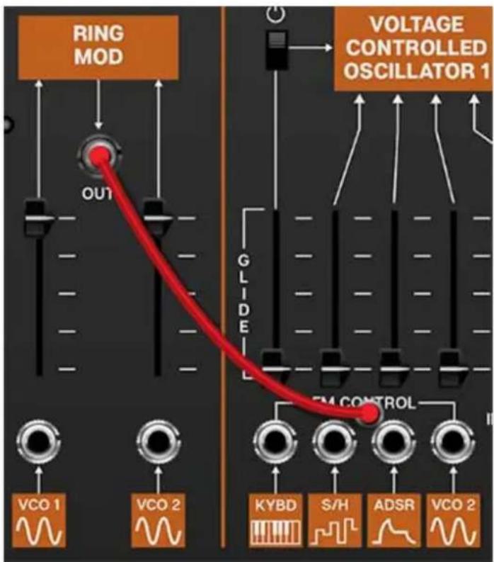
Patching A Cable- Simply click on a jack, drag the cable to the desired destination jack and release the mouse button. Cables can be
Inputs and Output Jacks
Unlike a hardware modular synth, where some jacks can be used as inputs or outputs, all Voltage Modular jacks are exclusively an input or an output. To clarify this, when a jack is clicked and held to patch a cable, jacks not available as destinations are grayed out. For example, if you're patching a cable from an output jack, all other output jacks are temporarily grayed out. The same applies if you're patching a cable from an input jack- all other input jacks are grayed out.
That said, cables can be patched in either direction - in other words, CA2600 doesn't care if the connection is initiated on the input jack or output jack side.
flowchart
graph TD
    subgraph Initial Freq
        A["LO 64' 32' 16' 8' 4' 2'"] --> B["FINE TUNE"]
        B --> C["KYBD CV IN"]
        C --> D["VOLTAGE CONTROLLED OSCILLATOR 1"]
        D --> E["SUB"]
        E --> F["FM CONTROL"]
        F --> G["PW INITIAL PWM"]
        G --> H["KYBD S/H ADIGR VCO 1"]
        H --> I["LFD"]
        I --> J["LFQ"]
    end

    subgraph Initial Freq
        K["LO 64' 32' 16' 8' 4' 2'"] --> L["FINE TUNE"]
        L --> M["KEYB CV IN"]
        M --> N["VOLTAGE CONTROLLED OSCILLATOR 2"]
        N --> O["SYNC"]
        O --> P["LFQ"]
        P --> Q["LFQ"]

    end

    subgraph Initial Freq
        R["KEYB CV IN"] --> S["VOLTAGE CONTROLLED OSCILLATOR 3"]
        S --> T["SYNC"]
        T --> U["LFQ"]
        U --> V["LFQ"]

    end

    subgraph Noise Source
        W["MIDI IN"] --> X["CV OUTS"]
        X --> Y["PITCH GATE VEL MOD BEND"]
        Y --> Z["NOTE PRODINITY"]
        Z --> AA["LAST LOW HIGH DUO"]
        AA --> AB["SECOND VOICE CV SEMA TONES"]
        AB --> AC["OUT"]
        AC --> AD["LOW FREO"]
        AD --> AE["WHITE"]
        AE --> AF["PINK"]
        AF --> AG["LOW FREO"]
        AG --> AH["OUT"]
    end

    subgraph Voltage Processors
        AI["VOLTAGE PROCESSORS"] --> AJ["1/2/3/4 OUT"]
        AJ --> AK["5/8 OUT"]
        AK --> AL["LAD TIME →"]
        AL --> AM["LAM →"]
        AM --> AN["7 OUT"]
        AN --> AO["8 OUT"]
    end

    subgraph Sample & Hold
        AP["SAMPLE & HOLD"] --> AQ["S/H OUT"]
        AQ --> AR["ALN ELECTRONIC SWITCH"]
        AR --> AS["B/N ELEC SWITCH OUT"]
        AS --> AT["INT CLOCK OUT"]
        AT --> AU["LAV/UL RATE INT CLOCK OUT"]
        AU --> AV["LEVEL OUT"]
        AV --> AW["INT CLOCK OUT"]

    end
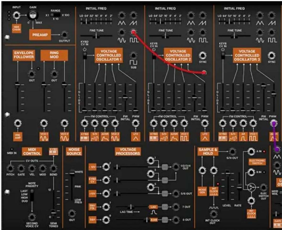
In the screenshot above, Oscillator 1's square wave output is being patched, causing all of other output jacks to temporarily gray out, with all input jacks available as potential destinations.
Disconnecting A Cable- Cables can be disconnected by grabbing one end of a jack and dragging to any area that isn't a jack, or by right-clicking on a jack and selecting Disconnect Cables.
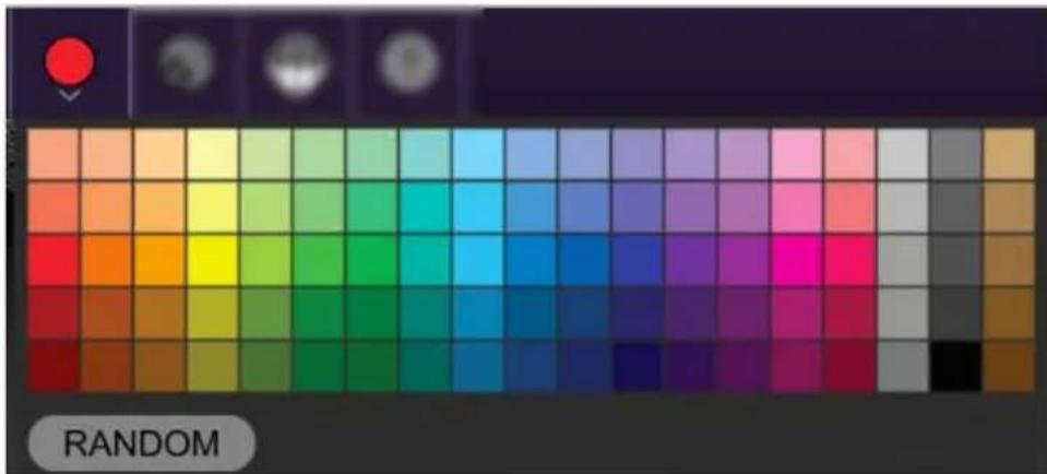
Selecting Cable Colors- There are a couple of ways to select cable colors. The most obvious way is to click the colored dot in the top menu bar to reveal the color picker palette and select a global color. By "global," this means all newly patched cables will appear in the chosen color (or a random color, if Random is selected). Existing cables are not affected.
To change the color of an existing patched cable, right-click on one of the jacks it's connected to, then click a new color. This changes only that cable, and won't affect the global cable color in the top menu bar.
- Super Handy "Pre-Patching" Cable Color Selection- Right-clicking a jack that doesn't have a cable plugged in opens the color palette and changes the global color; the same as clicking the color selector in the top menu bar. This is convenient for specifying a cable color prior to patching a new cable.
natural_image
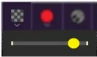
User interface control panel with slider and three colored buttons (red, yellow, gray) on dark background (no text or symbols)Adjust Cable Transparency. Clicking the checkerboard icon in the top toolbar displays the cable transparency horizontal slider. Slide this to the left for more transparent cables, or to the right for more opaque cables.
Show/Hide Cables- Clicking this hides or shows all cables. It has no effect on sounds, and its status does not save with patches. Cables visibility can also be toggled with the key shortcuts [CTRL-D] (PC) or [⌘-D] (Mac).
Advanced Cable Shortcuts and Tricks
Following are some not-so-obvious shortcuts that seriously speed up patching operations.
The Unlimited Mult Hiding Beneath Every Jack
flowchart
graph TD
    A["PWM"] --> B["FM CONTROL"]
    B --> C["S/H"]
    C --> D["ADSR"]
    D --> E["VCO 1"]
    E --> F["LFO"]
    F --> G["AGE SORS"]
    G --> H["1/2/3/4 OUT"]
    H --> I["3"]
    I --> J["Sample & HOLD"]
    J --> K["S/H OUT"]
    K --> L["ELECTRONIC SWITCH"]
    L --> M["B IN"]
    M --> N["ADSR"]
    N --> O["RING MOD"]
    O --> P["VCO 1"]
    P --> Q["5"]
    Q --> R["PGND"]
    R --> S["PGND"]
    S --> T["PGND"]
    T --> U["PGND"]
    U --> V["PGND"]
    V --> W["PGND"]
    W --> X["PGND"]
    X --> Y["PGND"]
    Y --> Z["PGND"]
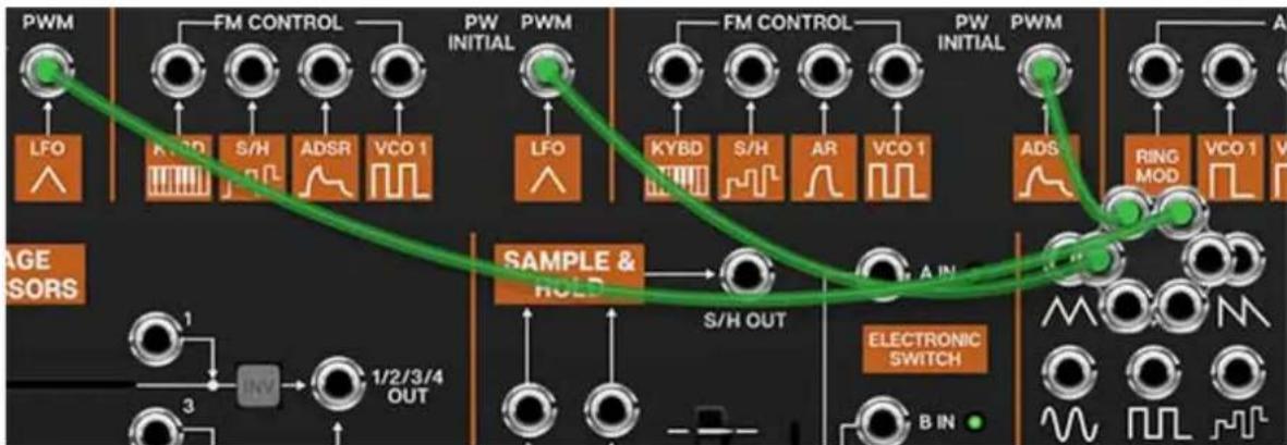
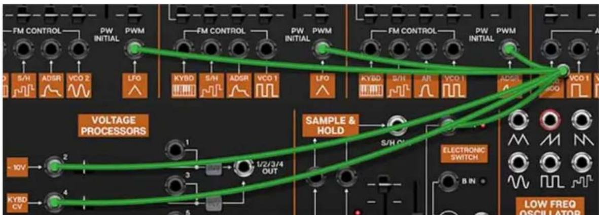
In the image above, we've routed three cables from the LFO ramp wave output to the PWM inputs of each oscillator. Single-clicking on any CA2600 input or output jack reveals a six-way multiple jack (aka, a "mult"), which is super convenient for routing or mixing multiple sources. The mult stays visible while routing or if the mouse is hovering on it, and is hidden when a cable is routed.
Though mults initially display six jacks, if more than six connections are added, the "ring" grows and additional jacks appear. Here't the nifty part: there's no limit to the number of mult jacks that can be added to a connection, so patch like crazy!
Move or Unplug Multiple Cables Plugged Into A Single Jack
Multiple cables plugged into a single jack can be move all at once by holding the [SHIFT] key and clicking and dragging to a new destination. If the mouse button is released in an "empty" area, this is a quick way to unplug all cables into a jack at once.
Rapidly Routing A Cable To Multiple Destinations
This one's not so obvious, but it's really handy. To patch cables from a single jack to multiple destinations, press and hold the [CTRL] key in Windows or
the [✗] key on Mac, click the source jack, then click as many destination jacks as desired and release the modifier key when you're done. This works with input or output jacks, and is particularly useful for patching pitch and gate CV's from the I/O panel to multiple oscillators or envelope generators.
Voltage Controlled Oscillators
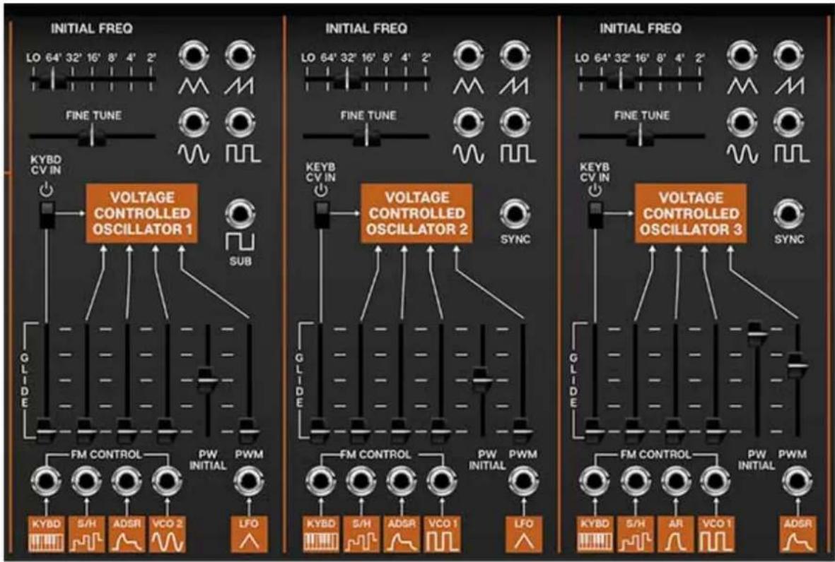
CA2600 includes three super-wide range oscillators that accurately model the imperfect waveforms of vintage ARP synthesizers. Unlike the original ARP 2600, all three have full functionality with all waveforms and pulse-width modulation capabilities. Their controls are almost identical, with a few sensible differences.
Initial Freq- Sets the basic pitch of the oscillator, displayed in traditional organ footage. Unlike the original ARP 2600, with its continuous pitch Initial Freqslider, CA2600 has stepped settings displayed in traditional organ octaves, making it much easier to tune to useful musical intervals. The Lo setting is beneath the audible range and is intended for use as a mod source.
Fine Tune- This can be used to fatten up two-oscillator patches by detuning a small amount, or for "building-in" a set interval. Its range is a smidge over a fifth, up or down.
Like a vintage ARP 2600, the oscillators do not have switches for wave selection. Instead, VCO 1's and 2's pulse wave and VCO 3's ramp wave are normalled to the Voltage Controlled Filter(VCF) audio inputs and gain sliders. To select a different oscillator wave, patch a cable from the
appropriate VCO wave output jack to any of the VCF Audio input jacks to override the normalled routing.
Waveform output jacks- All three oscillators include triangle, ramp, sine, and pulse wave outputs; oscillator 1 adds a Sub out - this is a 50% square wave one octave below the Initial Freq setting. The Sub out is not affected by pulse width settings.
All oscillators have a ramp wave out, but no saw wave out (i.e. reverse ramp). There is no audible difference between ramp and saw waves if you're using the oscillators as audio sources, but you may want saw waves for "falling" mod effects when using the oscillators as low-frequency control sources. This can be accomplished by patching a ramp wave output to one of the inverters in the Voltage Processors section. (more on this in the, you guessed it, Voltage Processors section)
Sync (VCO 2 and VCO 3 only)- Feeding a wave or signal to this force resets the start of the waveform to the beginning of its cycle. Most often used to create the "tearing" sweep sounds made famous in The Cars' "Let's Go," by routing the output of another oscillator to the Hard Sync input and sweeping the pitch of the first oscillator.
Hard Sync is also useful when creating drum and percussion sounds to ensure that the wave starts precisely at the beginning of its cycle.
Keyb CV In- This switch connects or disconnects incoming MIDI pitch control. This defaults to on position, for standard keyboard (or sequencer) playing. Turning it off is useful for drones or sound effects when you don't want oscillator pitch to be affected by keyboard CV. Pitch can still be controlled with Initial Freq and Fine Tunecontrols as well as all FM Control CV inputs.
Glide- Also known as "portamento," glide delays the voltage change between pitches for a sliding effect. Though the Glide slider is situated above the normalled Pitch source and jack, it is not an attenuator for it, but it is in the signal path, so it will affect the normalled pitch CV or any signal plugged into the Kybd FM jack. CA2600 includes separate Glide controls for each oscillator - applying glide to only one oscillator is nice effect.
FM Control inputs and attenuators- These are the normalled and jack frequency modulation inputs for the oscillators. The slider control above each jack is an attenuator, affecting the amount of the normalled source, or if a cable is plugged into the jack, the amount of the signal from the patched source.
PW Initial- This sets the width or "duty-cycle" of the pulse wave. It has no effect on any other waveform. This defaults to 50%, i.e., a perfect square wave. Moving the slider up or down narrows its width as well as the thickness of sound until it almost disappears at its extremes.
PWM Control input and attenuator- Allows CV control of the pulse wave pulse width.
The table below shows the default sources and destinations for all three VCO's:
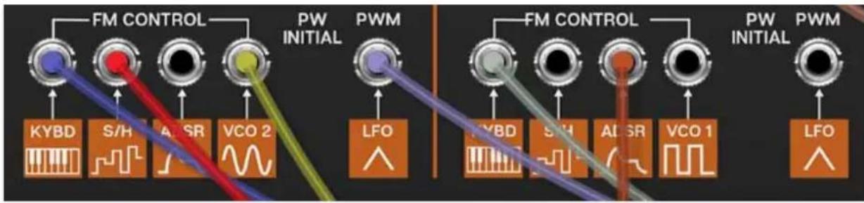
MOD SOURCE NAME NORMALLED SOURCE NORMALLED D
| VCO 1/FM Control - Keyb CV incoming MIDI note data VCO 1 frequen | ||
| VCO 1/FM Control - S/H sample and hold output VCO 1 frequen | ||
| VCO 1/FM Control - ADSR ADSR envelope output VCO 1 frequen | ||
| VCO 1/FM Control - VCO 2 Sine VCO 2 sine wave output VCO 1 frequen | ||
| VCO 1/PWM - LFO Triangle LFO triangle output VCO 1 pulse wi | ||
| VCO 2/FM Control - Keyb CV incoming MIDI note data VCO 2 frequen | ||
| VCO 2/FM Control - S/H sample and hold output VCO 2 frequen | ||
| VCO 2/FM Control - AR AR envelope output VCO 2 frequen | ||
| VCO 2/FM Control - VCO 1 Pulse VCO 1 pulse wave output VCO 2 frequen | ||
| VCO 2/PWM - LFO Triangle LFO triangle output VCO 2 pulse wi | ||
| VCO 3/FM Control - Keyb CV incoming MIDI note data VCO 3 frequen | ||
| VCO 3/FM Control - S/H sample and hold output VCO 3 frequen | ||
| VCO 3/FM Control - AR AR envelope output VCO 3 frequen | ||
| VCO 3/FM Control - VCO 1 Pulse VCO 1 pulse wave output VCO 3 frequen | ||
| VCO 3/PWM - ADSR ADSR envelope output VCO 3 pulse wi |
Voltage Controlled Filter
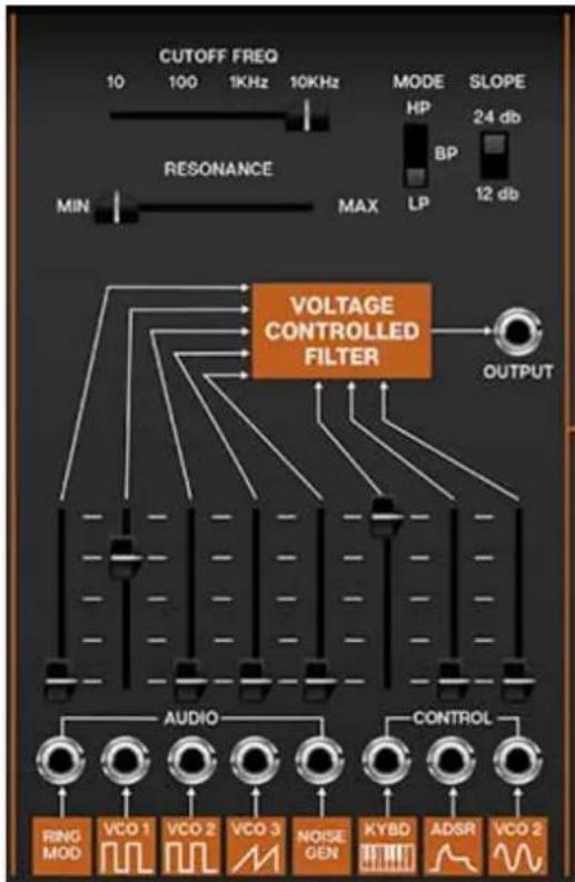
CA2600's filter section models the early ladder-style filter used in early ARP synthesizers, but unlike the original ARP 2600, It can be switched between lowpass, bandpass, and highpass modes, with 12- or 24-db per octave slopes.
If you're not familiar with how filters work, a lowpass filter allows frequencies below the cutoff frequency setting to pass through, but blocks frequencies above the cutoff frequency. A highpass filter does opposite: it allows frequencies above the cutoff frequency setting to pass through, but blocks frequencies below the cutoff frequency. In practice, this means a lowpass filter is useful for removing high frequencies, and a highpass filter is useful for removing low frequencies. A bandpass filter combines both lowpass and highpass filters thus allowing the "in-between" frequencies to pass.
Modulating cutoff frequencies via envelope generators, low-frequency oscillators, and more opens the door to endless tone colors.
Cutoff Freq- Sets the frequency where attenuation begins. Attenuation occurs above (lowpass mode) or below the cutoff frequency (highpass mode). In the case of a bandpass filter, the cutoff setting determines a center freq with a band of frequencies above and below passing through.
Resonance- Emphasizes sound energy at and around the current cutoff frequency by adding feedback from the filter's output back to its input. At lower settings, this can be used to create mild resonances such as those heard in acoustic instruments. At more extreme settings, resonance can create a pure sine wave at its own frequency (you can adjust its pitch with the Cutoff knob). Be careful with this knob as it can get loud at extreme settings.
Mode- Selects highpass, bandpass, or lowpass modes (as described above).
Slope- The nature of how a filter works is that frequencies "fall off" above or below the cutoff frequency. Slope adjusts the steepness of this slope. Set to lowpass mode, a 12db per/octave filter has a shallower slope, whereas a 24db per/octave filter has a steeper slope (as well as more pronounced character with the resonance knob turned up).
Output jack- The direct audio out of the VCF section, routable to any CA2600 input..
Audio inputs and attenuators- These are the filter's audio inputs; these effectively act as a mixer for all audio sources routed through the filter. When the input jacks are used, any CA2600 audio output can be routed through the filter. Although there are "only" five jack inputs, CA-2600's unlimited mult jacks allow an unlimited number of sources to be routed to the filter.
The slider control above each jack is an attenuator, affecting the amount of the normalled source, or if a cable is plugged into the jack, the amount of the signal from the patched source.
Control inputs and attenuators- These are the frequency modulation inputs, affecting cutoff frequency. Because these work additively with the Cutoff Freq slider setting, it's generally a good idea to turn down the initial Cutoff Freq setting when using mod sources. The slider control above each jack is an attenuator, affecting the amount of the normalled source, or if a cable is plugged into the jack, the amount of the signal from the patched source.
When the Resonance control is toward max, the filter will "ring"- used in conjunction with the Keyb Control slider, this allows the filter to act as an additional sine wave oscillator. It's particularly effective when carefully mixed with the noise generator for half-noise/half-tonal "snowflake" tones.
The table below shows the filter's default sources and destinations.
| MOD SOURCE/AUDIO INPUT NAME | NORMALLED SOURCE | NORMALLED DESTINATION |
| VCF/Audio Input - Ring Mod ring mod output VCF audio input | ||
| VCF/Audio Input - VCO 1 Pulse VCO 1 pulse wave output VCF audio input | ||
| VCF/Audio Input - VCO 2 Pulse VCO 2 pulse wave output VCF audio input | ||
| VCF/Audio Input - VCO 3 Ramp VCO 3 ramp wave output VCF audio input | ||
| VCF/Audio Input - Noise noise generator output VCF audio input | ||
| VCF/Control - Keyb CV incoming MIDI note data VCF cutoff frequ | ||
| VCF/Control - ADSR ADSR envelope output VCF cutoff frequ | ||
| VCF/Control - VCO 2 sine VCO 2 sine wave output VCF cutoff frequ | ||
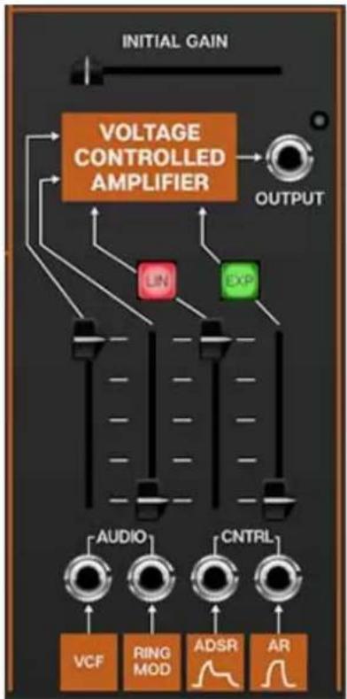
flowchart
graph TD
    A["INITIAL GAIN"] --> B["VOLTAGE CONTROLLED AMPLIFIER"]
    B --> C["OUTPUT"]
    B --> D["UN"]
    B --> E["EXP"]
    D --> F["AUDIO"]
    E --> G["CNTRL"]
    F --> H["VCF"]
    G --> I["RING MOD"]
    G --> J["ADSR"]
    G --> K["AR"]
Voltage Controlled Amplifier
You can think of the Voltage Controlled Amplifier (VCA) as a "gate" to start, stop, and shape the volume of audio or control signals. Applying a simple gate voltage will abruptly open and close the VCA; the CV output of an envelope generator allows shaping of audio and control signals with more finesse.
Initial Gain- Sets the static gain of the amplifier; a good analogy would be opening a faucet. For standard instrument-type sounds, you'll likely leave this set to minimum, and use AR and ADSR envelope generators CV's to control the VCA. Turning up the Initial Gain is useful for "hands-off" droning sounds.
If you're trying to figure out why CA2600 is continuously making noise and won't shut up, the first thing to check is VCA Initial Gain.
Output jack- Audio output of the VCA; this allows routing the signal anywhere desired. The LED next to the jack lights to indicate signal level.
Audio inputs and attenuators- These are the VCA audio input. Although there are only two jack inputs, CA-2600's unlimited mult jacks allow an unlimited number of sources to be routed to the amplifier.
The slider control above each jack is an attenuator, affecting the amount of the normalled source, or if a cable is plugged into the jack, the amount of the signal from the patched source.
Control inputs and attenuators- These are the gain modulation inputs, affecting VCA level. These work additively with the Initial Gain slider setting, it's generally a good idea to turn it down to zero when using mod sources. The slider control above each jack is an attenuator, affecting the amount of the normalled source, or if a cable is plugged into the jack, the amount of the signal from the patched source.
The table below shows the filter's default sources and destinations.
| MOD SOURCE/AUDIO INPUT NAME | NORMALLED SOURCE | NORMALLED DESTINATION |
| VCA/Audio Input - VCF filter output VCA audio input | ||
| VCA/Audio Input - Ring Mod ring mod output VCA audio input | ||
| VCA/Control - ADSR ADSR envelope VCA amplitude | ||
| VCA/Control - AR AR envelope VCA amplitude | ||
ADSR and AR Envelope Generators
The Cat includes two independent envelope generators; one is a standard ADSR (attack, decay, sustain, release), and the other is an ASR (attack, sustain, release). These are generally used to shape VCA amplitude contours and VCF cutoff frequency, but can be used to control other Cat parameters.
ADSR Envelope Generator
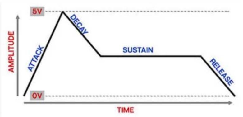
If you're not familiar with how envelope generators work, here's how an ADSR works:
line
| Time | Amplitude | |------|---------| | 0 | 0V | | Peak | 5V | | Sustain | 5V | | Release | 0V |When The Cat sees a gate voltage from a note, the envelope generator outputs a dynamically changing voltage, according to the settings of its four stages. The attack stage defines how long it takes for the output voltage to rise from 0 to 5 volts. Once the attack stage reaches 5V, it moves to the decay phase, which defines how long it takes to fall from 5V to the setting of the Sustain phase. Unlike the attack, decay, and release phases, which define times, sustain simply sets the held voltage level following the attack and decay phases - this equates to the envelope output level while holding down a key. Finally, the release slider defines the length of time it takes for the voltage to fall back to 0V when the gate input voltage is removed, i.e. when the key is released.
Atk (Attack)- Defines the length of time for voltage to rise from 0V to 5V when a key is played.
Dec (Decay)- Defines the length of time for voltage to fall from the attack stage 5V peak to sustain stage setting.
Sus (Sustain)- Sets the voltage level following attack and decay phases while a note is held.
Rel (Release)- Defines the length of time for voltage to fall from sustain level to 0V when a key is released.
Vel- Sets the degree to which keyboard velocity affects overall envelope output. A setting of Min equates to no effect on the envelope voltages; as the slider setting is increased, keyboard velocity has a greater effect on overall envelope generator output. You could think of this control as working "backwards" in the sense that low settings mean the envelope generator outputs its full voltage range regardless of key pressure, whereas cranking it to Max means that playing keys very lightly greatly reduces the overall envelope voltages.
ADSR Repeat- This is a somewhat unique feature that causes the LFO to automatically trigger the ADSR envelope generator.
- Gated- The ADSR envelope is triggered by the LFO when keys are held.
- Off- ADSR Repeat is disabled.
- Auto- The ADSR envelope is triggered by the LFO continuously, i.e., without pressing any keys.
AR Envelope Generator
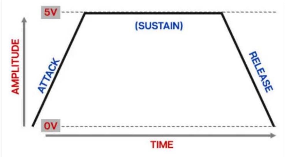
A simple envelope generator with attack and release segments only. The "AR" name is actually a bit of a misnomer - because it sustains at full level when a key is held down, it's actually an attack/sustain/release envelope (ASR).
area
| Time | Amplitude | |------|---------| | 0 | 0V | | 5V | 5V | | 0V | 0V | | 5V | 5V | | 0V | 0V |The AR envelope functions a little differently than the ADSR envelope. When a 5V gate voltage is applied, it moves through the attack segment and remains at maximum as long as the key is held (equivalent to an ADSR envelope with its sustain control set to maximum). The release slider defines the length of time it takes for the voltage to fall back to 0V when the gate input voltage is removed, i.e. when the key is released.
A (Attack)- Defines the length of time for voltage to rise from 0V to 5V when the gate voltage is applied.
R (Release)- Defines the length of time for voltage to fall from 5V sustain level to 0V once a key is released.
Vel- Sets the degree to which keyboard velocity affects overall envelope output. A setting of Min equates to no effect on the envelope voltages; as the slider setting is increased, keyboard velocity has a greater effect on overall envelope generator output. You could think of this control as working "backwards" in the sense that low settings mean the envelope generator outputs its full voltage range regardless of key pressure, whereas cranking it to Max means that playing keys very lightly greatly reduces the overall envelope voltages.
Sample+Hold Controls
Technically the Sample+Hold section isn't really a transient generator parameter, but we suppose this is where panel space was available on the original instrument - in the words of Emperor Joseph II in Amadeus: "...well then, there it is."
Sample+Hold Crash Course
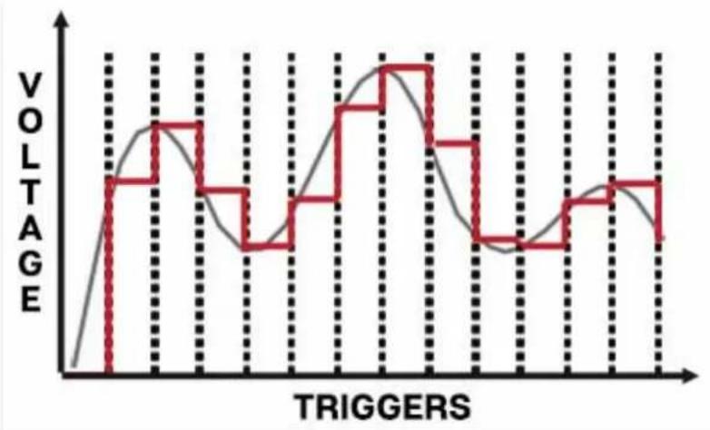
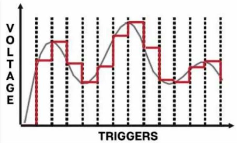
A sample+hold module is an analog-style synthesis tool that repetitively “samples” an input signal (i.e. checks to see what the voltage level is at that instant) and outputs a held voltage until triggered again (i.e. checks the voltage at that instant).
In the image below, the smooth gray line shows a continuous input signal. Each time the module is triggered the current voltage is “sampled” and “held” until the next trigger. The red line shows the held output signal.
line
| TRIGGERS | VOLTAGE | | -------- | ------- | | 0 | 0 | | 1 | 1 | | 2 | 2 | | 3 | 3 | | 4 | 4 | | 5 | 5 | | 6 | 6 | | 7 | 7 | | 8 | 8 | | 9 | 9 | | 10 | 10 | | 11 | 11 | | 12 | 12 | | 13 | 13 | | 14 | 14 | | 15 | 15 | | 16 | 16 | | 17 | 17 | | 18 | 18 | | 19 | 19 | | 20 | 20 | | 21 | 21 | | 22 | 22 | | 23 | 23 | | 24 | 24 | | 25 | 25 | | 26 | 26 | | 27 | 27 | | 28 | 28 | | 29 | 29 | | 30 | 30 | | 31 | 31 | | 32 | 32 | | 33 | 33 | | 34 | 34 | | 35 | 35 | | 36 | 36 | | 37 | 37 | | 38 | 38 | | 39 | 39 | | 40 | 40 | | 41 | 41 | | 42 | 42 | | 43 | 43 | | 44 | 44 | | 45 | 45 | | 46 | 46 | | 47 | 47 | | 48 | 48 | | 49 | 49 | | 50 | 50 | | 51 | 51 | | 52 | 52 | | 53 | 53 | | 54 | 54 | | 55 | 55 | | 56 | 56 | | 57 | 57 | | 58 | 58 | | 59 | 59 | | 60 | 60 | | 61 | 61 | | 62 | 62 | | 63 | 63 | | 64 | 64 | | 65 | 65 | | 66 | 66 | | 67 | 67 | | 68 | 68 | | 69 | 69 | | 70 | 70 | | 71 | 71 | | 72 | 72 | | 73 | 73 | | 74 | 74 | | 75 | 75 | | 76 | 76 | | 77 | 77 | | 78 | 78 | | 79 | 79 | | 80 | 80 | | 81 | 81 | | 82 | 82 | | 83 | 83 | | 84 | 84 | | 85 | 85 | | 86 | 86 | | 87 | 87 | | 88 | 88 | | 89 | 89 | | 90 | 90 | | 91 | 91 | | 92 | 92 | | 93 | 93 | | 94 | 94 | | 95 | 95 | | 96 | 96 | | 97 | 97 | | 98 | 98 | | 99 | 99 | | >100 | <100 |White noise is often used as an input source to generate a random stepped-CV signal. Modulating the pitch of an oscillator with this will create the classic sample and hold sound often heard in sci-fi movies (famously as the voice of R2-D2).
Sample+Hold Controls
S+H Glide- Adds a "slew" to make the S+H voltages glide from voltage to the next. The higher the setting, the slower the glide.
S+H source switch- Selects the input sampling source. Noise uses the noise source; this results in completely random voltages. Using VCO 1 or VCO 2 as a source can result in more predictable stepped pseudo sequencer-like patterns.
Master Section
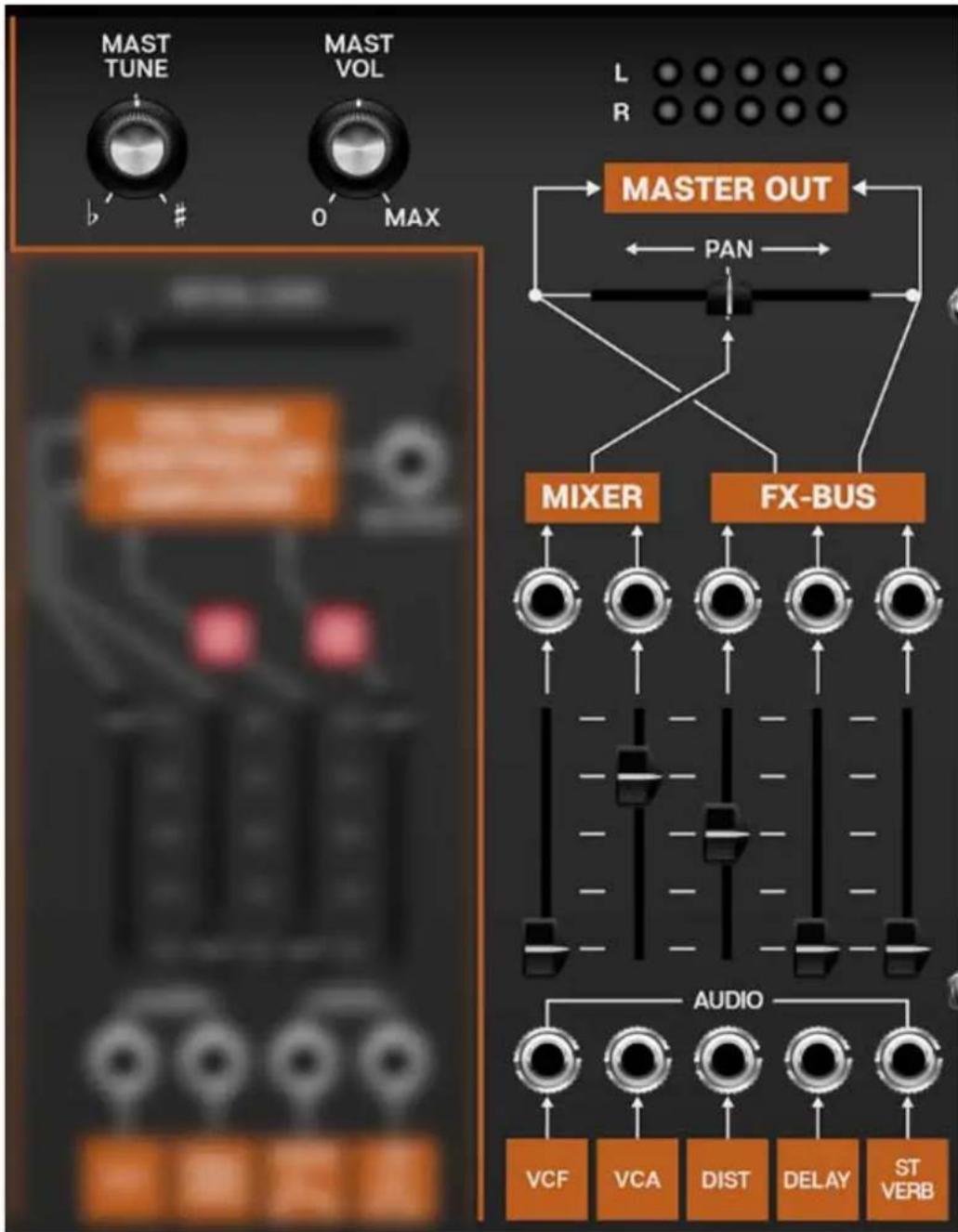
Master Tune- Sets master tuning up or down by a half-step.
Master Volume- Sets CA2600 master volume.
Output Meters- Not really a control, but this displays the master output. Like any other meter, it's best to keep these out of the red.
Pan- Adjusts the position of the dry VCF and VCA outputs between the left and right channels. This is useful if for panning the dry vs. effected signals.
Master Input Mixer
The Master Section's inputs jacks and faders are the final output mixer. As with CA2600's other sections, the orange boxes beneath the faders indicated the normalled input routings, and can be overridden with patch cables by plugging into the jacks above them.
Mixer Upper Output jacks- The jacks above the faders are outputs. Their levels are affected by the fader amount. They do not break the signal flow to the master output bus; think of them as extra points to tap signals for further routing and mangling.
The table below shows the filter's default sources and destinations.
AUDIO INPUT NAME NORMALLED SOURCE NORMALLED DE
Master Out/Audio Input - VCF VCF output master out bus /
Master Out/Audio Input - VCA VCA output master out bus /
Master Out/Audio Input - Dist distortion effect output master out bus /
Master Out/Audio Input - Del delay effect output master out bus /
Master Out/Audio Input - St Verb reverb effect output master out bus /
flowchart
graph TD
    A["INPUT"] --> B["GAIN"]
    B --> C["RANGE X1 100"]
    C --> D["PREAMP"]
    D --> E["OUTPUT"]
    F["SIDE CHAIN"] --> B
    G["0"] --> D
    H["MAX"] --> D
Preamp and Sidechain Input
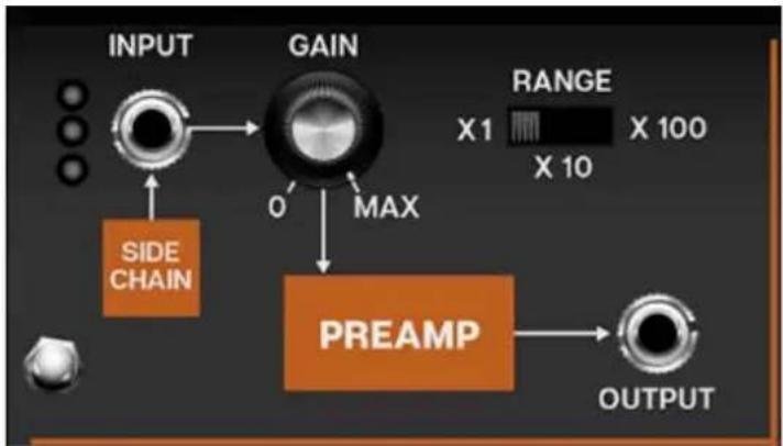
The Preamp and Sidechain input section enables processing of the external audio signals.
Sidechain normalled input and jack- Obviously you won't be able to plug real cables into the front-panel jack (unless you know something we don't), so the default routing is to receive signals from a DAW sidechain signal path. The specifics of sidechain routing vary dependent on DAW software, but once the signal is routed to CA2600, the three-LED meter in the corner will display signal level. You'll ideally want the first two green LED's to illuminate, and avoid the top red LED.
As with other normalled connections, the default sidechain routing can be overridden by plugging any CA2600 output signal into the jack above the orange box.
Using The Sidechain Input in Standalone Mode
If CA2600 is running in standalone mode (i.e. not as a DAW virtual instrument), the sidechain input can still be used, provided your computer system audio hardware has input capabilities.
To select the input source, click the Settings gear in the top tool bar, and click the Audio/MIDI icon. The sidechain input source can be selected via the Input pop-up menu.
Gain- Sets the incoming signal input level. The gain amount is affected a great deal by the Range switch.
Range- Allows three different amplification levels. Note that CA2600 includes a very analog-style overdrive at high Gain and Range settings. This really useful when processing electric guitar signals (and exactly what Pete Townshend was known to do on Who classics such as "Who Are You," and "Going Mobile.")
Output- The preamp section output; allows routing to any other section for processing.
Tuning- Sets master tuning up or down by a half-step.
Output Meters- Not really a control, but this displays the master output. Like any other meter, it's best to keep these out of the red.
MIDI Control
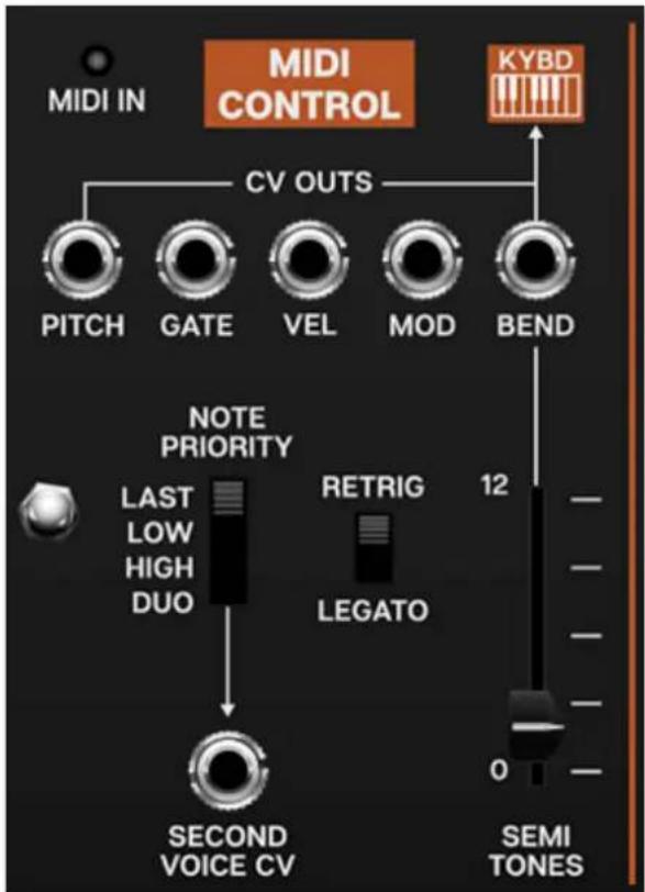
The MIDI Control section selects whether CA2600 plays in mono (single-note) or duophonic modes (two-note polyphony) and contains individual CV outputs, as well as a pitch bend depth control. It's basically the incoming "traffic director" of CA2600.
MIDI In- Illuminates to indicate incoming MIDI note data. Betcha never would've guessed that?
CV Outs
- Pitch- Pitch CV. This is normalled to the oscillators (Kybd) as well as one of the filter control inputs.
- Gate- This is an "on/off" voltage typically used for engaging envelope generators. The gate out is normalled to both the ADSR and AR envelope generators, but can be useful for other purposes.
- Velocity- Outputs a voltage upon keydown that varies from 0-5V, dependent on how hard the key is struck. Amongst other things, this is useful for controlling filter cutoff amount and amplitude envelope intensity.
- Mod Wheel- Outputs a constant voltage dependent on mod wheel position.
- Bend / Semi Tones slider- Outputs a negative or positive voltage as the pitch wheel is moved from its center position. Its maximum output level (i.e., bend depth) is controlled with the Semi Tonesslider. At max position, pitch bend range is one octave, up or down.
As shown by the orange Kybd box, pitch bend is normalled to the oscillator FM Control Kybd CV inputs. This means pitch bend will work without plugging in any cables (provided the Semi Tonescontrol is set above 0). Plugging a patch cable into one of the oscillator Kybd inputs will disable the pitch bend connection, but you can always mult another patch cable from the Bend output to the oscillator Kybd CV input(s) to regain pitch bend.
Note Priority- CA2600 will usually be played as a monophonic (i.e. one-note-at-a-time) synthesizer, but it includes ARP's model 3620 keyboard controller "duophonic" (dual-voice) mode.
- Last- This is the default voice mode. If more than one key is pressed, the most recently struck note will always take priority.
- Low- If more than key is pressed, the lowest note will always sound. This how the original ARP 2600 works (as well as most vintage monophonic synths).
- High- If more than key is pressed, the highest note will always sound.
- Duo (Duophonic) / Second Voice CV- Duophonic mode is based on the original ARP 2600's primitive duophonic circuit. The primary pitch output is always the lowest key pressed. The Second Voice CV pitch output is always the highest key pressed. When a new key is pressed, the highest and lowest key voltages are sampled and held by the two outputs. If only one key is pressed, the highest and lowest key voltages will be identical. However, as soon as a second key is pressed, the highest key voltage is sampled and sent to the Second Voice output, and the lowest key voltage is sampled and sent to the Pitch output. In this mode, legato playing often gives undesirable results, as any time two keys overlap, even for a moment, their voltages are split between the two outputs.
Duo mode is also the most desirable note priority mode when performing covers of songs by The Captain and Tennille, Donny and Marie, and Peaches & Herb.
Retrigger/Legato- If Retrigger is selected, CA2600's envelopes will retrigger from the start every time a new key is pressed. If Legato is selected, the envelopes will only retrigger if no other notes are currently held. Legato mode is useful for emulating the sounds of some acoustic instruments - for example, the sound of plucking a note on a guitar, then sliding on the string to different notes without plucking again. Retrigger mode generally feels more responsive to play and is useful for more aggressive passages.
Incidentally, almost all vintage monophonic analog synths are legato-mode only (including the original ARP 2600), as this was a technological limitation.
Noise Source
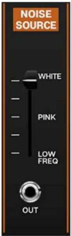
CA2600 includes a noise source capable of generating a spectrum of noise tones with a continuously variable control.
- White Noise- Random noise containing all frequencies at relatively equal amplitude.
- Pink Noise- Random noise with equal energy per octave. This has audibly more low-frequency content than white noise.
- Low Frequency Noise- Random noise with an even stronger low-frequency bias than pink noise.
Out jack- The Noise Generator's output is normalled to one of the filter inputs, but the jack can be used to route noise wherever desired. Keep in mind that in addition to audio applications, noise can be used as a modulation source.
flowchart
graph LR
    A["AR"] --> B["VCA 2 CTRL"]
    C["-10V"] --> D["ATTENUATOR #1"]
    E["KYBD CV"] --> F["ATTENUATOR #2"]
    G["+10V"] --> H["ATTENUATOR #3"]
    I["ENV FOL"] --> J["LAG TIME"]
    K["S&H"] --> L["QUANTIZE IN LEVEL"]
    B --> M["+"]
    D --> N["3"]
    F --> O["5"]
    H --> P["5/6 OUT"]
    J --> Q["LAG"]
    L --> R["QUAN"]
    M --> S["INV"]
    N --> T["INV"]
    O --> U["INV"]
    P --> V["INV"]
    Q --> W["7 OUT"]
    R --> X["8 OUT"]
    style A fill:#f9f,stroke:#333
    style C fill:#f9f,stroke:#333
    style E fill:#f9f,stroke:#333
    style G fill:#f9f,stroke:#333
    style I fill:#f9f,stroke:#333
    style K fill:#f9f,stroke:#333
    style M fill:#ccf,stroke:#333
    style N fill:#ccf,stroke:#333
    style O fill:#ccf,stroke:#333
    style P fill:#ccf,stroke:#333
    style Q fill:#ccf,stroke:#333
    style R fill:#ccf,stroke:#333
    style S fill:#ccf,stroke:#333
    style T fill:#ccf,stroke:#333
    style U fill:#ccf,stroke:#333
    style V fill:#ccf,stroke:#333
    style W fill:#ccf,stroke:#333
Voltage Processors
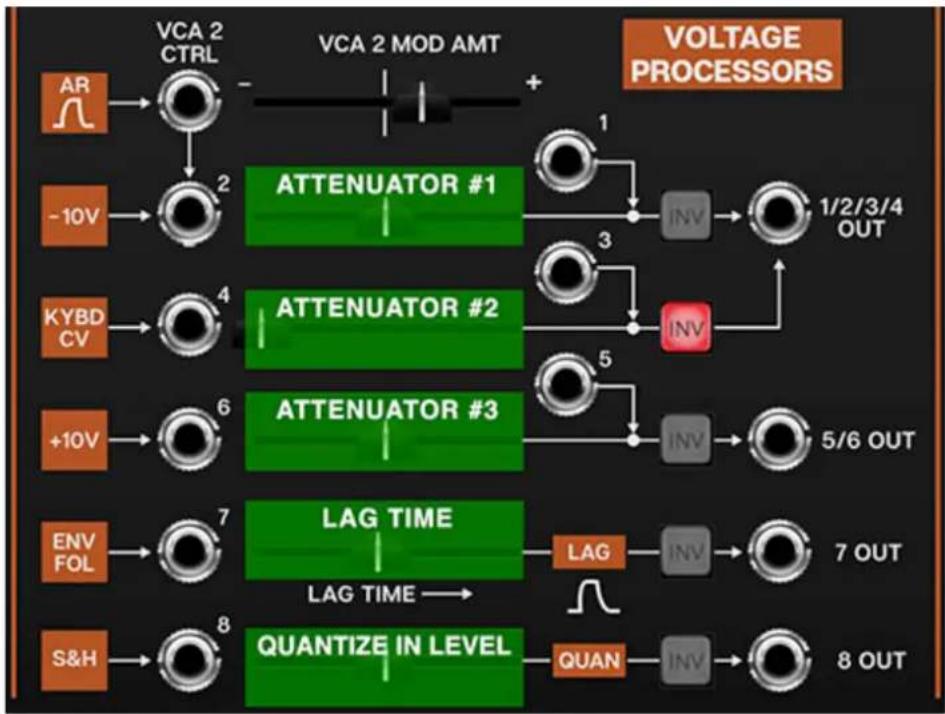
The Voltage Processors section is perhaps the most misunderstood section of the original ARP 2600, but it's actually easy to use, and very useful. It essentially consists of three invertible signal attenuators (the first one with an integrated VCA), a lag generator (aka, glide), and a 1/2 step voltage quantizer. As with other 2600 inputs, the input jacks include normalled signal paths for ease of use.
Since the horizontal sliders aren't labeled on the panel, we've Photoshopped in the green boxes and extra labels in the screenshot above to make it easier to understand the following descriptions:
Voltage Processor Attenuator 1/2 and VCA 2 (Input jacks #1 and #2)-This is a signal attenuator with an integrated VCA. If you're not familiar with attenuators, it's just a fancy word for "amount" control. The attenuator #1 slider acts as a static level control for signals plugged into the #2 jack. If the slider is set fully left, it's at zero; sliding to the right increases the amount. The level can be CV controlled if a cable is patched to the VCA 2 Ctrl input. The top VCA 2 Mod Amt slider determines the amount of CV controlling slider attenuator #1's amount. The VCA 2 Mod Amt slider is bipolar; that is, it can reduce or increase the amount of of slider 2 depending on its position from the middle (and whether the incoming CV is positive or negative). The VCA 2 Mod Amt slider is at zero in center position.
To attenuate an external signal, override the normalled source by plugging a cable into the #2 jack. The attenuated output will be on the 1/2/3/4 Out jack. If nothing is plugged into the #2 input, a constant -10V signal is normalled to the #2 jack. This can be used to "bias" any CA2600 CV control input. The slider will control the voltage amount from zero, down to -10 volts.
Jack #1 directly feeds the 1/2/3/4 Out jack - it bypasses the attenuator #1 slider. This is useful if you want to invert a signal without altering its level. On the original 2600, this jack also acted as an additional mix input; but since you can stack as many inputs as you like on a single jack in CA2600, it's not really necessary.
- Invert (Inv) button- This inverts the polarity of any signals traveling through, and has many uses. If the -10V source is being used, enabling the Inv button will make the voltage range 0 to +10V. The Inv button is also useful for "reversing" oscillators waveforms, particularly for transforming the ramp wave to a saw wave. All five voltage processor amount sliders include an invert button.
Voltage Processor Attenuator 2- Almost identical to attenuator #1, but the normalled source is the keyboard MIDI pitch CV. In conjunction with the Inv button, this can be used to recreate the jazz legend Joe Zawinul's famous "reverse keyboard" trick (where low keys play highest notes and vice-versa). Simply hit attenuator #2's Inv button, then patch the 1/2/3/4 Out jack to the oscillator FM Control Kybd input jacks. The normalled input can be overridden by patching to jack #4. Jack #3 directly feeds the 1/2/3/4 Out jack - it bypasses the attenuator #2 slider.
Voltage Processor Attenuator 3- Attenuator #3 is also almost identical to attenuator #1, but the normalled constant voltage source is +10V instead of -10V (but it can be changed to -10V by engaging the Inv button). The normalled input can be overridden by patching to jack #6. Jack #5 directly feeds the 5/6 Out jack - it bypasses the attenuator #3 slider.
Voltage Processor Lag Time (Lag)- The Lag Time slider looks like the others, but it's not - it's not an attenuator, it's a lag (aka glide or slew) generator. Lag generators are most commonly used to create sliding effects by slowing down the stepped changes in pitch from a keyboard, but they're useful for other things, such as smoothing the changing the stepped voltages from random/sample & hold voltages.
Note that CA2600 has an individual lag generator built into each oscillator, so you won't need to use the Voltage Processors lag generator for keyboard
glide.
Voltage Processor Quantize In Level (Quantizer)- Control voltages fed through the quantizer voltage processor will be rounded to the nearest 1/12V step, i.e., the nearest half-step. This is useful for transforming constantly changing (ramp, saw, triangle, or sine waves) or randomly stepped (sample & hold) waves into musically useful melodies. Note that quantizing occurs after the attenuator slider, so adjusting it alters the amount of signal going to the quantizer, which effectively changes the pitch range.
In order to properly hear 1/2 step pitches, make sure to set the mod destination attenuator (usually one of the oscillator FM Control inputs) all they way up. Use the horizontal slider and the speed of whatever you're feeding into the quantizer to fine-tune the note range and speed.
Since we love making tables, here's one illustrating all inputs, outputs, and processing of the Voltage Processors section:
| SLIDER NORMALLED SOURCE | SECONDARY INPUT? | OUTPU JACK |
| VCA 2 Mod Amount VCA 2 CTRL jack only N/A N/A | ||
| Attenuator #1 -10 volt source yes 1/2/3/4 | ||
| Attenuator #2 keyboard pitch CV yes 1/2/3/4 | ||
| Attenuator #3 +10 volt source yes 5/6 Ou | ||
| Lag Time envelope follower output no 7 Out | ||
| Quantize Input Level sample & hold output | no 8 Out |
Sample & Hold and Electronic Switch
flowchart
graph TD
    A["SAMPLE & HOLD"] --> B["S/H OUT"]
    C["NOISE GEN"] --> D["INT CLOCK OUT"]
    D --> E["LEVEL RATE"]
    F["A IN"] --> G["ELECTRONIC SWITCH"]
    H["B IN"] --> I["ELEC SWITCH OUT"]
    I --> J["INT CLOCK OUT"]
    J --> K["LEVEL RATE"]
    L["LEVEL RATE"] --> M["NOT"]
    N["S/H OUT"] --> O["NOT"]
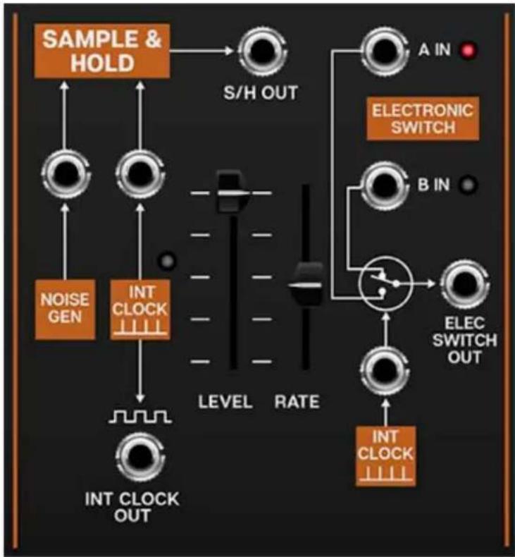
The sample and hold section repeatedly "samples" a varying input signal voltage, and outputs the "snapshot" voltage (i.e. a constant voltage) until it is triggered to sample again. Note that when we say "sample," we're referring to a simple incoming voltage - this isn't an audio sampler that you can sample and playback beats with. (Though this is the basic principle of how digital audio samplers operate).
Therefore a sample and hold has two inputs - the sample input, i.e. where it's grabbing the voltage samples from, and a clock input, which determines the duration between sample.
The Electronic Switch is alternates two input sources feeding a single output jack. By default, its normalled to the Sample & Hold clock, but it has a jack allowing switching from any CV source.
Sample & Hold
line
| TRIGGERS | VOLTAGE | | -------- | ------- | | 0 | 0 | | 1 | 0.5 | | 2 | 0.7 | | 3 | 0.6 | | 4 | 0.4 | | 5 | 0.3 | | 6 | 0.5 | | 7 | 0.8 | | 8 | 0.9 | | 9 | 0.7 | | 10 | 0.5 | | 11 | 0.4 | | 12 | 0.6 | | 13 | 0.7 | | 14 | 0.8 | | 15 | 0.6 | | 16 | 0.5 | | 17 | 0.7 | | 18 | 0.8 | | 19 | 0.6 | | 20 | 0.5 |Sample Source (Noise Gen) input and jack- The noise generator is the default sample signal source. Because a noise source has all possible frequencies distributed in a random fashion, it makes an excellent source for "grabbing" completely random voltages. This signal can then be used to modulate oscillator pitch or filter frequency.
Alternate sample signals can be substituted by patching to the jack above the orange Noise Gen box. When modulating oscillator pitch, constantly moving low frequency waveforms such as triangle, sine, ramp, and saw work particularly well. Differing sample Rate slider and low-frequency oscillator rates yield endless melodic permutations.
Clock Source (Int Clock) input, jack, and rate LED- By default, the Sample & Hold uses its internal clock source to determine the rate at which the sample source is sampled. The LED above the orange box flashes to indicate the current clock rate.
Internal Clock Out jack- This output allows the Sample & Hold clock to be routed to any CA2600 input.
Level- Overall amount control for the S/H Out jack.
Rate- Sets the speed of the Sample & Hold's internal clock.
Sync button- Engaging the Sync button locks the Sample & Hold clock to master tempo. When engaged, the Rate slider snaps to note values ranging from 1/64th note triplet to 8 beats. Sync mode locks to the tempo in the top toolbar when using the CA2600 standalone version or the current project tempo when the plug-in version is used in a DAW.
Electronic Switch
The electronic switch alternates between two patched inputs sources at rate specified by the Sample & Hold clock or an alternate clock/switching source.
A and B input jacks and LEDs- These are the two inputs and can be CA2600 audio or control signals. The red and green LEDs will glow to show which input is currently active.
Clock Source (Int Clock) input and jack- By default, the Electronic Switch uses the Sample & Hold internal clock source to determine the rate at which the A and B inputs alternate. The Sample & Hold internal clock can be overridden by plugging any signal source into the jack above the Int Clock orange box. The Electronic Switch alternates any time it sees a 5V spike, so the "clock" source doesn't need to change at regular intervals - a keyboard gate signal could be used, for example.
Electronic Switch Out- Output jack for the alternating signal.
Low Frequency Oscillator
A low frequency oscillator or "LFO," is similar to an audio oscillator, but it typically runs at frequencies below the range of human hearing, and it isn't used an audio source. Instead, its cycling waveforms are used as a control source to add modulation to oscillators, filters, and amplifiers.
A typical application would be to slightly modulate an oscillator's frequency to create vibrato (pitch modulation), or to modulate a VCA's amplitude to create a tremolo effect (amplitude modulation). Modulating the cutoff frequency of a filter can create a dubstep-style wobble, or if modulated very slowly, long sweeping tonal shifts.
Unlike the original ARP 2600, we've added an "extra" low frequency oscillator (LFO) - on the original, it was necessary to use one of the voltage controlled oscillators for modulation. The extra LFO leaves all three oscillators available for audio (or extended mod purposes).
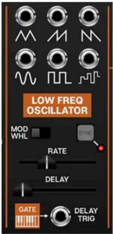
Waveform output jacks- Available waveforms include triangle, ramp, sawtooth, sine, square, and random.
Mod Wheel switch and LED- Sliding this to the right normals incoming MIDI mod wheel data to control overall LFO depth; the LED to the right will light. This simplifies setting up CA-2600 for vibrato, pulse-width mod, or filter wah wah with a mod wheel - turn the switch on, patch a cable from the LFO
Out to one or multiple oscillator FM mod jacks, and push up the corresponding FM slider.
Important Note: If the Mod Wheel switch is on and your controller's mod wheel is at zero, the LFO won't have any signal output, so... if the LFO doesn't seem to be working, make sure the Mod Wheel switch is in the off position (or push up your controller's mod wheel).
Sync- Engaging the Sync button locks the LFO master tempo. When engaged, the Rate slider snaps to note values ranging from 1/64th note triplet to 8 beats. Sync mode locks to the tempo in the top toolbar when using the CA2600 standalone version or the current project tempo when the plug-in version is used in a DAW.
Rate- Sets the rate of the LFO from 0.01 Hz-20 Hz.
Delay- Moving this slider up gradually delays the onset of LFO depth - think of it like an attack control for LFO depth. By default, the delay is triggered by the keyboard gate (i.e. playing MIDI notes), but can be overridden by plugging a cable into the adjacent jack (try this with a slow clock, for example). The delay range is 0 to 3000 ms.
Note about the Mod Wheel switch and LFO Delay: If the Mod Wheel switch is in the on position (LED lit), the Delay slider grays out and is disabled (because you wouldn't want the onset of LFO mod delayed when controlling mod amount with a mod wheel).
Effects
CA2600's effect implementation is somewhat unique in the sense that, instead of being "tacked on" and hidden behind menus, they're integrated into the main interface, and have CV inputs for almost all of their controls. Applying CV's to the effects parameters can range from subtle (reverb mix) to total insanity (delay time mod with high feedback settings).
Keep in mind that all three effects have separate level sliders in the Master Out section (beneath the orange FX-Bus block); in addition to enabling the effects with the red buttons, you'll need to turn up the sliders in the Master Out section to hear them.
Note that the effects have no wet/dry controls - they are always 100% wet in the Master Out faders. Wet/dry signal mix is achieved by blending in the Master Out VCF and/or VCA signals. This arrangement is useful, because it allows a great deal of flexibility if, for example, you'd like totally wet reverb signals (incidentally, "all-wet" reverb signals aren't possible with the original ARP 2600 master mixer).
Distortion
flowchart
graph LR
    A["VCA"] --> B["AUDIO"]
    C["LFO"] --> D["CTRL"]
    B --> E["DIST AMT"]
    D --> F["DIST CTRL"]
    E --> G["+"]
    F --> G
    G --> H["OUTPUT"]
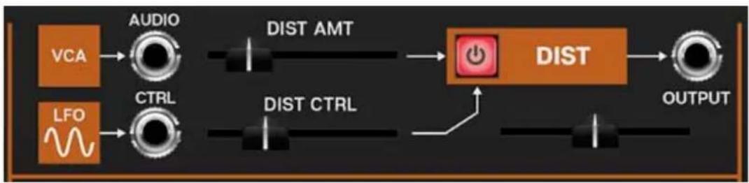
On/Off- The red button in the orange box enables and disables the distortion effect.
FM Control inputs and attenuators- These are the normalled and jack parameter modulation inputs. The slider control to the right of each jack is an attenuator, affecting the amount of the normalled source, or if a cable is plugged into the jack, the amount of the signal from the patched source. This is the same as bulk of parameters in the top section of the control panel; we just turned them sideways to save space. See table below for control details.
| MOD SOURCE NAME | NORMALLED SOURCE | NORMALLED DESTINATION |
Distortion/Audio Input - VCA VCA output distortion input amount
Distortion/Control - LFO LFO output amount of distortion
Output level slider and jack- The slider beneath the orange DIST block sets the output level. The output jack allows the distorted signal to be routed to any CA2600 input. You don't necessarily need to use the output jack, as the signal it normalled to the Master Out FX-Bus/Audio section.
Delay
flowchart
graph LR
    A["VCA"] --> B["AUDIO"]
    B --> C["INPUT LEVEL"]
    C --> D["OUTPUT"]
    E["LFO"] --> F["CTRL"]
    F --> G["INPUT CTRL"]
    G --> H["TIME CTRL"]
    H --> I["FDBCK CTRL"]
    I --> J["MOD WHL"]
    J --> K["DAMPING"]
    K --> L["DAMPING"]
    M["DELAY"] --> N["OUTPUT"]
    O["INV"] --> P["SYNC"]
    Q["TIME"] --> R["TIME"]
    S["FEEDBACK"] --> T["Feedback"]
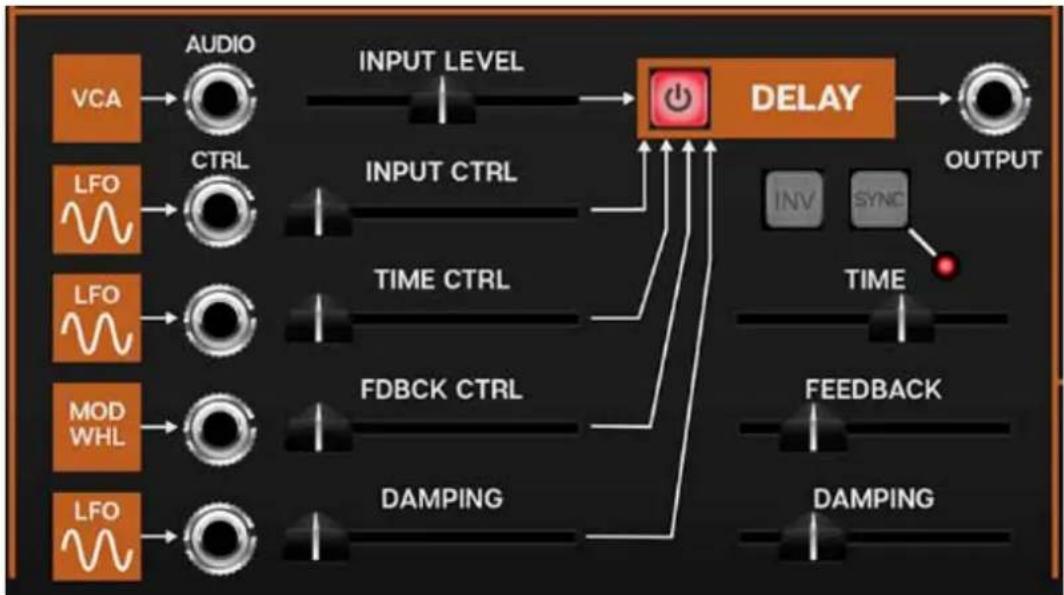
On/Off- The red button in the orange box enables and disables the delay effect.
FM Control inputs and attenuators- These are the normalled and jack parameter modulation inputs. The slider control to the right of each jack is an attenuator, affecting the amount of the normalled source, or if a cable is plugged into the jack, the amount of the signal from the patched source. See table below for control details.
| MOD SOURCE NAME | NORMALLED SOURCE | NORMALLED DESTINATION |
| Delay/Audio Input - VCA VCA output delay input amount | ||
| Delay/Control - LFO LFO output delay input | ||
| Delay/Control - LFO LFO output delay time | ||
| Delay/Control - Mod Whl mod wheel delay feedback amount | ||
| Delay/Control - LFO LFO output damping amount | ||
Invert (Inv)- Inverts the delayed signal from the incoming dry signal. Along with the Damping slider, this can be useful if repeats are stacking up and audibly "cancelling out." It's also useful for achieving different tones when using the delay at short times for flanging and chorus effects (in the 1-20 ms range).
Sync- Engaging the Sync button locks the delays time to master tempo. When engaged, the Rate slider snaps to note values ranging from 1/64th-note triplet to 8 beats. Sync mode locks to the tempo in the top toolbar when using the CA-2600 standalone version or the current project tempo when the plug-in version is used in a DAW.
Time- Sets delay time, from 1 to 2000 ms. If the Sync button is enabled, time settings snap to synchronized note values. The LED number display shows the current time.
Feedback- Routes the output to the input for additional repeats. Be careful at high settings as this can result in runaway feedback madness.
Damping- Attenuates high-frequencies as the slider amount is increased. Not only does this create more natural sounding decays, it also reduces the "stacking" effect that occurs with high feedback levels.
Output jack- The output jack allows the fully wet delay signal to be routed to any CA2600 input. You don't necessarily need to use the output jack, as the signal it normalled to the Master Out FX-Bus/Audio section.
Reverb
flowchart
graph LR
    A["VCA"] --> B["AUDIO"]
    B --> C["INPUT LEVEL"]
    C --> D["REVERB"]
    E["LFO"] --> F["CTRL"]
    F --> G["INPUT CTRL"]
    G --> D
    H["LFO"] --> I["CTRL"]
    I --> J["DECAY CTRL"]
    J --> D
    K["MOD WHL"] --> L["CTRL"]
    L --> M["DAMPING CTRL"]
    M --> N["DECAY"]
    N --> O["DAMPING"]
    O --> P["L+R SUM OUTPUT"]
    Q["SPRING"] --> R["TYPE PLATE"]
    S["PLATE"] --> T["TYPE PLATE"]
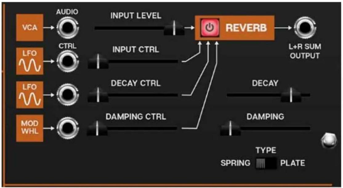
On/Off- The red button in the orange box enables and disables the reverb effect.
FM Control inputs and attenuators- These are the normalled and jack parameter modulation inputs. The slider control to the right of each jack is an attenuator, affecting the amount of the normalled source, or if a cable is plugged into the jack, the amount of the signal from the patched source. See table below for control details.
| MOD SOURCE NAME | NORMALLED SOURCE | NORMALLED DESTINATION |
| Reverb/Audio Input - VCA VCA output reverb input amount | ||
| Reverb/Control - LFO LFO output reverb input | ||
| Reverb/Control - LFO LFO output reverb decay time | ||
| Delay/Control - Mod Whl mod wheel reverb damping | ||
L+R Output jack- The output jack allows the fully wet reverb signal to be routed to any CA2600 input. You don't necessarily need to use the output jack, as the signal it normalled to the Master Out FX-Bus/Audio section.
About CA2600's stereo reverb- The reverb section is takes CA2600's mono output and converts it to a wide-sounding stereo signal. The single
Master Out/FX-Bux St Verb fader affects the level of both channels to the master output bus, however both channels are summed to a mono signal at the output jack in the Reverb effect section. This was done to simplify patching, because CA2600 doesn't have any stereo input destinations.
Decay- Sets the overall length of reverb; the actual time varies dependent on the reverb type.
Type - Spring/Plate- Allows selection of two different types of reverb. Spring sounds like the crude spring-type reverb found in the original ARP 2600; plate is has more hifi and refined sound, as well as longer decay times.
Damp- Attenuates high-frequencies as the slider amount is increased for more natural reverb sounds.
Settings
Clicking the settings gear opens a window with multiple tabs for configuring various "under-the-hood" settings. These are mostly set-and-forget kind of parameters - all the stuff you'll want to tweak is on the front panel, because that's how we do things around here!
General
- Add Undo For Control Changes With The Mouse- Enabling this allows undo of control adjustments and cable patching. You'll want this on if you want the ability to undo all aspects of patch editing and programming.
- Load Last Preset On Startup (Standalone Only)- Automatically loads the last preset used when CA2600 standalone version is started.
- Create A Log File For Usage- This creates a text document of CA2600's internal routines during use. Our tech support may request these docs should you encounter any issues. Clicking Show Log Folder opens the folder containing CA2600 log file docs.
natural_image
Sketch of a person using a power saw to cut through a tree in a wooded area (no text or symbols)Cherry Audio strictly adheres to safe forestry practices when creating log files.
- Preset Folder- Displays the current location of CA2600's sound presets. This can be changed by clicking and typing in the field.
- Browse... - Displays the current location of preset folder in the file manager.
- Set Default- Sets the current displayed Preset Folder path as the default location
- Clear Cache Files- Deletes all log files, temporary sounds, and the image cache.
Interface
Allows customization ofCA2600's user interface settings.
- Reset To Default Window Size- Resets the CA2600 workspace to 1817x800 pixels (i.e. 100% zoom). Use this to reset the window size if CA2600's workspace somehow becomes too large for your display and can't be resized.
- Theme- Select from three color schemes, "Blue Marvin," (earliest ARP 2600's), Gray (1971-1976), or Orange and Black (1977-1980). This only changes the color, sound is not altered in any way.
- Tooltip Delay- Tooltips are those informative bits of text that pop up when hovering over a control (go ahead and try it, we'll wait...). The Tooltip Delaysetting defines how long you must hover before the tooltip pops up.
- Knob Movement- Defines which how mouse movements related to turning onscreen knobs. It defaults to Vertical Drag, but can be changed to Horizontal Drag, or Rotary Drag.
- On Control Double-Click- Defines what happens when the mouse is double-clicked on a control. If Edit Value is selected, an exact number can be entered by typing the number and hitting [ENTER] or [RETURN]. If Sets Default Value is selected, double-clicking a control resets it to its default value.
- Mouse Wheel Adjusts Control Value- Enabling this lets you adjust knob, slider, and switch values by moving the mouse wheel. This works great with a standard mouse wheel, but you'll want to disable it if you're using an Apple Magic Mouse (which will move the control AND scroll the window).
- Show Tooltips On Any Control Change- Displays parameter tooltips/values next to controls any time a control is changed, i.e. if a control is moved via an assigned MIDI controller.
- Show Control Tooltips Under Mouse- Displays parameter tooltips/values when the mouse is hovered over a control or as a control is moved with mouse clicked.
- MIDI Program Changes Should Change Current Preset- Allows MIDI program change messages to change CA2600 patches.
- Ask To Save Presets- This opens a dialog window asking if you'd like to save changes if a patch has been edited and a new patch is selected. If you're the type that likes to click through presets and tweak a control here and there, it can be annoying to have a window pop-up asking if you'd like to save every time you switch presets - if you're that person, keep this off.
- Use Open GL Hardware Acceleration- If your computer has Open GL graphics capabilities, this can increase graphic performance.

Account
Settings for your personal login information and account.
- Email- Displays the email address of the current login.
- Update Login Info- Not a place for news about yacht-rock superstar, Kenny Loggins. Clicking this opens the same email and password login screen you’ll see when initially launching CA2600
- View Account Settings- This opens your personal account page on the Cherry Audio Store website containing information about purchases and more.
Software Update
- We often fix bugs and make improvements; below are options defining how CA2600 handles updates.
- Check For Update- Click this to see if an updated version of CA2600 is available.
Status-
- Automatically Install Updates- Updates are automatically downloaded and installed.
- Ask Before Installing Updates- By default, CA2600 automatically downloads new versions of modules when available. Checking this box defeats automatic updates and will ask if you'd like to install updates when they become available.
We'll never make changes that can potentially "break" existing patches but we recommend enabling Ask Before Installing Updates if you're using CA2600 for live performances or other "mission critical" situations.
- Never Install Updates- CA2600 never automatically installs updates.
- Show Updates On Toolbar- Checking this will display an icon in the toolbar letting you know there's an update available.
Show Notifications From Cherry Audio- We occasionally will fire off in-app advertisements; disabling this checkbox will hide them. We hate repetitive, annoying ads as much as you do, so we won't use this feature too often. When we do, we promise it'll be something super cool that'll you'll like, so we recommend leaving it on.
Cables
These preferences define how CA2600's virtual patch cables behave.
- Animate Cables- When checked, CA2600 cables will bend and dangle like real cables. This makes everything sound better (not really, but it looks cool).
- Move Cables Away- When checked, hovering over a cable (or multiple cable spaghetti) will temporarily shift them out of the way to make it easier to see modules beneath.
- 3D Cables- Checking this shades cables to appear more well, three-dimensional, No silly red and green glasses required.
- Draw Shadow- Causes cables to cast a shadow upon modules.
- Cable Thickness- Adjusts the thickness of all cables.
- Transparent Cables This works in conjunction with the Cable Transparency button discussed previously.
All Cables- Cable Transparencyslider affects all cables.
All But Current Jack - Hovering over a jack will make its cables opaque. If the Cable Transparency control is set to its maximum setting, Transparent Cables will have no effect.
- Show Signal Animation- Enabling this superimposes a stream of "marching ants" over cables displaying signal flow and direction. (They're
easier to see at wider cable width settings.) The Speed slider adjusts the speed of display, but has no effect on signals.
- Enable Animations For Jacks- Selecting this shows a nifty little animation when a jack is clicked to use its built-in mult. If you're a super impatient weirdo (like the guy typing this), unchecking this box disables the animation, which will make the mult pop up more quickly.
Audio/MIDI
Settings for audio and MIDI hardware input and output. This tab is only visible in the standalone version of CA2600.
- Output- Use this drop-down menu to choose a physical audio output source. This defaults to Built-In Line Output, i.e. your computer's onboard system audio, but you'll get better fidelity with an external professional audio interface. The biggest audible difference is usually reduced background noise or hum, but external audio hardware also offers greater flexibility in terms of number of inputs and outputs and built-in mic or low-level instruments pres (i.e. electric guitars). These are especially useful if you're using CA2600's external inputs to process sound.
The Test button will produce a sine wave when clicked; this will help with troubleshooting, aka, "WHY THE HECK ISN'T THIS MAKING ANY NOISE?!?"
- Input- Clicking the drop-down menu lets you select which physical input(s) feed CA2600's sidechain input (in the upper-left corner of the main panel). The small horizontal input meter to the right illuminates when the selected input is receiving an audio signal. And just to be super clear, this only applies to the standalone version of CA2600 - if you're using it as a virtual instrument, your DAW software will have a sidechain input routing menu.
- Sample Rate- This sets CA2600's global sample rate. Lower sample rates offer better performance, but if you have a fast computer, high sample rates may offer slightly improved fidelity.
- Audio Buffer Size- As with any digital audio app, this defines performance vs. note latency, and will largely depend upon computer CPU speed. A professional external audio interface will almost always exhibit better performance than “built-in” system audio. Lower settings will result in less latency (in the form of faster response to notes played), but will increase the chances of audio gapping or crackling noise.
- Active MIDI Inputs- Displays all available MIDI input sources, i.e. keyboards, pad controls, MIDI knob/fader control surfaces, etc. Check boxes to enable one or more devices.
MIDI Controllers Setup and The MIDI Tab
Assigning internal and external hardware controls adds a whole new dimension of control and musicality to patches, and it's really easy to do. The MIDI Tab is where all controller assignments can be viewed and tweaked. First we'll show how to assign an external hardware controller to a CA-2600 control, then we'll go over all parameters in the MIDI Tab.
Basic External Hardware Control Assignment
This is the quick, "I just want to assign a hardware control right now!," section. We recommend reading this whole section to best take advantage of CA-2600's swift MIDI control assignments.
In this example, we'll assign a hardware slider control to the filter cutoff frequency.
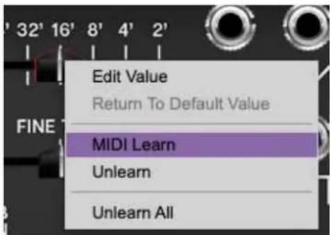
Begin by right-clicking on the Cutoff Freq slider in the Voltage Controlled Filter section and selecting MIDI Learn. A transparent blue overlay appears over the slider indicating that it's in learn mode. Now move the desired hardware control device. The blue overlay disappears and the hardware control will move the onscreen slider. If you get cold feet (or accidentally put the wrong control into learn mode), learn mode can be aborted by right-clicking and selecting Stop Learning.
This is the basic procedure for assigning hardware controllers to almost any CA-2600 control.
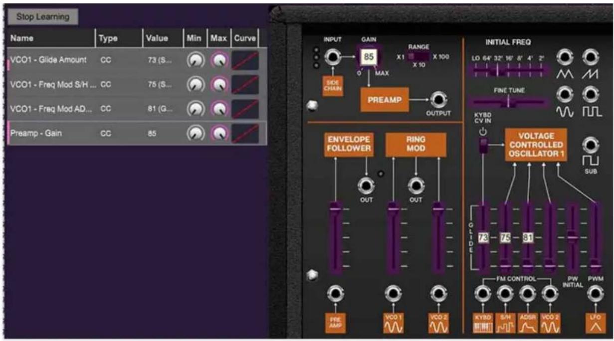
When in MIDI learn mode, any previously assigned controller numbers will show in squares. These indicate the MIDI continuous controller number of the assigned hardware control (these are also displayed in the MIDI library tab).
Once a MIDI controller has been assigned, in addition to real-time control of a CA-2600 parameter, you'll also be able to record and play back controller data from a DAW.
The MIDI Tab
This is command central for all MIDI controller assignments. Here you'll be able to see information about all currently assigned controllers and adjust control ranges.
To view or hide the MIDI Tab, click the MIDI button in the top toolbar.
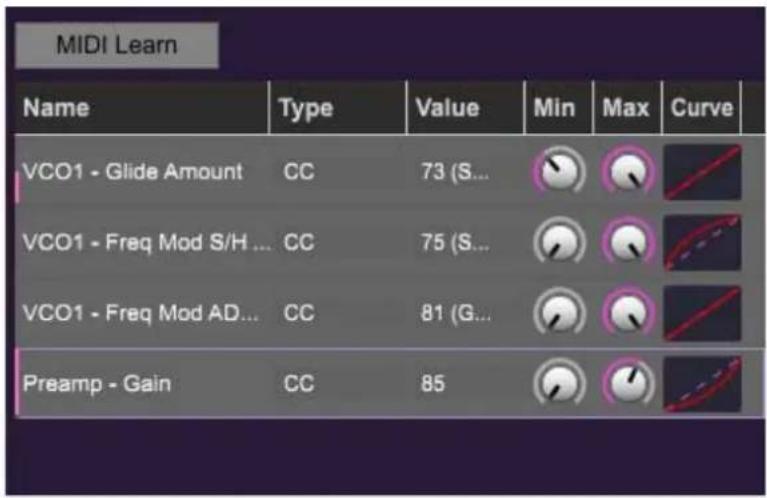
MIDI Learn button- This is almost exactly the same as enabling MIDI learn mode by right-clicking a control. Click the MIDI Learn button to enter learn mode (all controls turn blue). Unlike right-clicking on specific knobs, where CA-2600 automatically exits controller assignment mode, clicking the MIDI Learn knob "stays on" to enable assignment of multiple hardware controls. This is handy for quickly assigning a bunch of sliders or the buttons of a grid-style controller.
To assign controls, click MIDI Learn, click an on-screen control, move the desired hardware knob or slider, continue clicking and assigning on-screen controllers until all desired controls are assigned, then click Stop Learning to exit learn mode.
Remember that a single hardware knob和社会按钮 isn't limited to controlling just one parameter - a single hardware controller can simultaneously operate as many controls as you'd like. This "macro" control feature combined with customized ranges and curves for each assigned parameter is really powerful (see next section for a full explanation).
MIDI Tab Columns
Name- Displays the name of the parameter being controlled.
Type- There are five possible types of controller automation in CA-2600:
- Note- Notes played on a MIDI keyboard controller, expressed as C-1 to G9
- CC (MIDI Continuous Controller)- The standard 128 MIDI controller numbers as defined in the MIDI spec. More specifically, these are the controllers transmitted by hardware knob and slider controls. MIDI CC's can be used to control parameters in real-time or recorded and played back within DAW software.
- MMC (MIDI Machine Control)- The MIDI control protocol for tape machine-style transport controls. Back in the dark ages, this was used to control wonky old Tascam and Fostex reel-to-reel monsters, but it's useful if your MIDI controller has tape-style transport control buttons.
- Aftertouch- Besides sounding like a 1979 Neil Diamond record, some keyboard controllers transmit controller data when keys are pressed and released as they're held down. The vast majority of keyboard controllers with aftertouch transmit "mono" aftertouch only; in other words, aftertouch data is the sum of all keys to one single data stream.
- Key- This allows keys of the computer QWERTY keyboard to at as button controls for CA-2600's onscreen controls.
Value- Displays the specific automation controller. In the case of a Note this would show a MIDI note number (C-1 to G9, for a MIDI CC, this would be the MIDI CC controller number, etc. Clicking on the value opens a pop-up menu where all values are displayed and can be selected.
Min- Sets a limit on the lowest value any automation control can set a mapped controller to. This actually recalibrates the range of the automation controller to the remaining parameter range.
Max- Sets a limit on the highest value any automation control can set a mapped controller to. This actually recalibrates the range of the automation controller to the remaining parameter range.
- Super Tricky Min-Max Tricks Not only can parameter ranges be limited via the Min and Max knobs, mapped control destinations can be completely inverted by setting the Min knob all the way up and the Max knob all the way down (or anywhere in between).
Limiting and inverting parameter ranges with the Min/Max controls is particularly useful when multiplexing a single hardware control to operate multiple parameters. Along with the Curve control, the customization possibilities are super flexible.
Curve- These allow the customization of how incoming MIDI CC controls affect the movement of CA-2600's onscreen controls, ranging from exponential to linear to logarithmic curves.
MIDI Tab Column Configuration Right-Click Menus
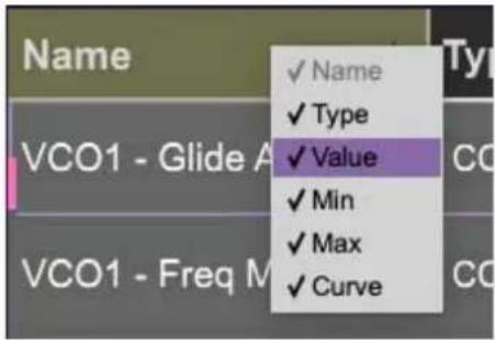
Right-clicking anywhere in the top row (Name, Type, Value, etc.) displays the column configuration menu. Checking/unchecking these allows hiding and display of each column. This has no effect on assignments.
MIDI Tab Parameters Right-Click
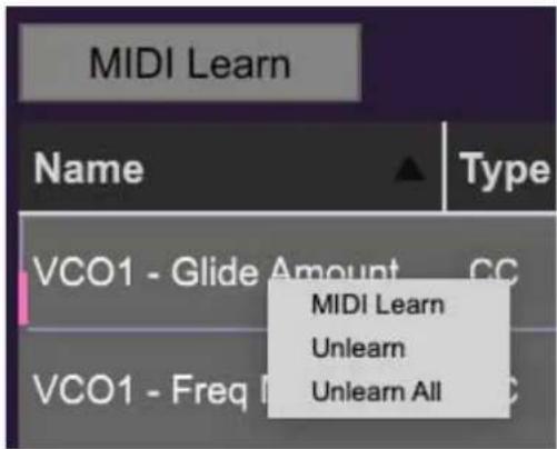
Right-clicking on an assigned parameter opens the menu above.
MIDI Learn- This is used to change the controller assigned to a particular parameter.
Unlearn- Deletes the selected automation parameter.
Unlearn All- Deletes all controller assignments for the patch. CA-2600 will display a warning dialog prior to deletion in order to thwart potential unlearn-related disasters.
![QWERTY Keyboard CONTROL VELOCITY: 90 BEND - / + MOD [0-9] SUSTAIN RESET C4 C5 OCT- OCT- STEP- W E T Y U O P A S D F G H J K L :](/content/2026/05/997507/images/c8e6d5320d8e568b318825c1ec7fe345d07c02ccf6c578365768cb1a866d9a38.jpg)
QWERTY Musical Typing Keyboard (MTK)
If you don't have a MIDI keyboard attached to your computer, the standard QWERTY computer keyboard can be used to play notes - we're pretty sure you've got one of those! We'll refer to this as the "MTK." Following is a list of MTK keyboard modifiers and functions:
natural_image
Abstract geometric logo with piano keys inside a circle on a dark purple background (no text or symbols)Opening and Closing the MTK - click the the circular keyboard icon in the top toolbar. To close the MTK, click the keyboard icon in the top toolbar, or click the X in the top right corner.
Play Notes- To trigger notes, simply press the corresponding computer keyboard key or mouse click the onscreen keys.
Adjust Currently Visible MTK Range- Slide the purple scroll bar horizontally to adjust the currently visible keyboard range.
Adjust Overall Visible Keyboard Range- Clicking and dragging the right edge of the MTL window allows the overall size of the window to be adjusted. This lets you view more or less of the onscreen keyboard. Note that the MTK window's borders cannot exceed the overall outside dimensions of the CA2600 window.
Shift Range Up/Down Octave- Click the OCT-and OCT+ buttons at the top left and right of the onscreen MTK. The current range is displayed above the
keyboard.
Shift Range Up/Down Semitone- Click the STEP- and STEP+ buttons at the bottom left and right of the onscreen MTK. The current range is displayed above the keyboard.
Hide/View Controllers- Clicking CONTROL at the far left hides and displays velocity, bender, mod, and sustain control parameters. Hiding the control view makes more space available for the keyboard.
Set Note Velocity- Move the purple VELOCITY bar to adjust the output velocity of notes.
Pitch Bend- To pitch a note or notes, press the + or - computer keyboard keys while playing a note. Notes will bend up to an octave. Notes can also be pitchbent by clicking the mouse in the Bendarea.
Mod Wheel- To add mod wheel modulation, press the number keys from 0-9 (above the character keys) while playing a note. The modulation amount will vary from none (0) to full modulation (9). Note that modulation will "stick" at the selected number; to disable modulation, click the 0 key. Mod can also be engaged by clicking the mouse in the mod bar area.
Sustain- The Sustain button mimics the functionality of a standard sustain pedal. Click the [TAB] key to engage sustain, or [SHIFT]+[TAB] to lock it. The Sustain button can also be engaged by mouse clicking it.
Reset- Initializes all MTK parameters including keyboard range and control parameters.
- Pre-Purchase Demo Mode
- Technical Assistance
- About This Manual
- Terminology
- Top Toolbar and Preset Browser
- Importing Presets with drag-and-drop
- The tempo display only appears in the standalone version of CA2600. VST, AU, and AAX plug-in versions receive tempo data from their host DAW app.
- Focus Button
- Preset List Right-Click Functions
- Semi-Normalled Patching
- To Cable, or Not to Cable?
- Using Cables
- Inputs and Output Jacks
- Advanced Cable Shortcuts and Tricks
- Move or Unplug Multiple Cables Plugged Into A Single Jack
- Rapidly Routing A Cable To Multiple Destinations
- Voltage Controlled Oscillators
- Voltage Controlled Filter
- Voltage Controlled Amplifier
- ADSR and AR Envelope Generators
- ADSR Envelope Generator
- AR Envelope Generator
- Sample+Hold Controls
- Sample+Hold Crash Course
- Master Section
- Master Input Mixer
- AUDIO INPUT NAME NORMALLED SOURCE NORMALLED DE
- Preamp and Sidechain Input
- Using The Sidechain Input in Standalone Mode
- MIDI Control
- CV Outs
- Noise Source
- Voltage Processors
- Sample & Hold and Electronic Switch
- Sample & Hold
- Electronic Switch
- Low Frequency Oscillator
- Effects
- Distortion
- Delay
- Reverb
- Settings
- General
- Interface
- Account
- Software Update
- Status-
- Cables
- Audio/MIDI
- MIDI Controllers Setup and The MIDI Tab
- Basic External Hardware Control Assignment
- The MIDI Tab
- MIDI Tab Columns
- MIDI Tab Column Configuration Right-Click Menus
- MIDI Tab Parameters Right-Click
- QWERTY Musical Typing Keyboard (MTK)
Brand : Cherry Audio
Model : CA2600
Category : Audio software