
ISC-M100100 - Machine de contrôle de sécurité Dahua Technology - Free user manual and instructions
Find the device manual for free ISC-M100100 Dahua Technology in PDF.


| Product Type | IP Network Camera |
| Model | ISC-M100100 |
| Brand | Dahua Technology |
| Resolution | 2 Megapixels (1920 x 1080) |
| Lens | 2.8 mm fixed |
| Night Vision | IR LED, up to 30 meters |
| Video Compression | H.265 / H.264 |
| Power Supply | DC 12V / PoE (802.3af) |
| Power Consumption | < 5.5W |
| Dimensions | 70 mm x 70 mm x 150 mm |
| Weight | 0.45 kg |
| Connectivity | Ethernet (RJ45), Built-in microphone |
| Storage | MicroSD slot (up to 256 GB) |
| AI Features | Motion detection, Face detection |
| Weather Rating | IP67 (outdoor use) |
| Operating Temperature | -30°C to 60°C |
| Mounting | Wall or ceiling mount |
| Included Accessories | Quick start guide, mounting screws, DC adapter |
| Certifications | CE, FCC, RoHS |
Frequently Asked Questions - ISC-M100100 Dahua Technology
User questions about ISC-M100100 Dahua Technology
0 question about this device. Answer the ones you know or ask your own.
Ask a new question about this device
Download the instructions for your Machine de contrôle de sécurité in PDF format for free! Find your manual ISC-M100100 - Dahua Technology and take your electronic device back in hand. On this page are published all the documents necessary for the use of your device. ISC-M100100 by Dahua Technology.
USER MANUAL ISC-M100100 Dahua Technology
AI Dual-energy Security Screening Machine User's Manual

natural_image
Abstract geometric composition with gray and red shapes (no text or symbols)Foreword
General
This manual introduces the installation, functions, and operations of the AI Dual-Energy Security Screening Machine (hereinafter referred to as the "Device"). Read carefully before using the device, and keep the manual safe for future reference.
Application Scope
This manual is mainly applicable to the following persons:
Administrator and operator of ISC series AI dual-energy X-ray security screening machine.
Models
ISC-M100100D
ISC-M100100
ISC-M6550D
ISC-M6550
ISC-M6040
ISC-M5030
Safety Instructions
The following categorized signal words with defined meaning might appear in the manual.
| Signal Words Meaning | |
 DANGER DANGER | Indicates a high potential hazard which, if not avoided, will result in death or serious injury. |
 WARNING WARNING | Indicates a medium or low potential hazard which, if not avoided, could result in slight or moderate injury. |
 CAUTION CAUTION | Indicates a potential risk which, if not avoided, could result in property damage, data loss, reductions in performance, or unpredictable results. |
 IPS IPS | Provides methods to help you solve a problem or save time. |
 TE TE | Provides additional information as a supplement to the text. |
UI Icon/Button
| Icon/Button Description | |
 | Add: Click it to unfold the hidden application interface. You can view or activate the application. |
| [BYYC] | Help: Point to it, and the interface shows guiding information. |
| [T880] | Expand: Click it and the hidden menu items are displayed. |
| [DSKW] | Check box that allows for selecting multiple menu items simultaneously.√means the item is selected. |
| [000] | Radio button that allows for selecting a menu item.○means the item is selected. |
| [001] | Drop-down list: Click it, and the drop-down menu items are displayed. |
| indicates the corresponding function is disabled. | |
| indicates the corresponding function is enabled. | |
| [CTZS]Search | Search bar: Enter the keyword, and then click .QMatching information is displayed. |
| TextBox: Allows for entering numbers, letters, Chinese characters, symbols, and more. | |
 | Refresh: Click it to get the latest saved settings. |
| [26AT] | Cancel: Click it to cancel unsaved settings and return to the previous menu interface. |
| Close: Click it to close the window. |
Privacy Protection Notice
As the device user or data controller, you might collect the personal data of others such as their face, fingerprints, and license plate number. You need to be in compliance with your local privacy protection laws and regulations to protect the legitimate rights and interests of other people by implementing measures which include but are not limited: Providing clear and visible identification to inform people of the existence of the surveillance area and provide required contact information.
Revision History
| Version | Revision Content | Release Time |
| V1.0.0 | First release. | January 2022 |
About the Manual
- The manual is for reference only. If there is inconsistency between the manual and the actual product, the actual product shall prevail.
• We are not liable for any loss caused by the operations that do not comply with the manual. - The manual would be updated according to the latest laws and regulations of related regions. For detailed information, see the paper manual, CD-ROM, QR code or our official website. If there is inconsistency between paper manual and the electronic version, the electronic version shall prevail.
- All the designs and software are subject to change without prior written notice. The product updates might cause some differences between the actual product and the manual. Please contact the customer service for the latest program and supplementary documentation.
- There still might be deviation in technical data, functions and operations description, or errors in print. If there is any doubt or dispute, please refer to our final explanation.
- Upgrade the reader software or try other mainstream reader software if the manual (in PDF format) cannot be opened.
- All trademarks, registered trademarks and the company names in the manual are the properties of their respective owners.
- Please visit our website, contact the supplier or customer service if there is any problem occurred when using the Device.
- If there is any uncertainty or controversy, please refer to our final explanation.
Important Safeguards and Warnings
This section introduces content covering the proper handling of the Device, hazard prevention, and prevention of property damage. Read carefully before using the Device, comply with the guidelines when using it.
Operation Requirements

WARNING
Before operating the Security Screening Machine, receive relevant training in radiation protection according to the requirements of local laws and regulations. If necessary, report the installation and operation of the Device to the local authority and conduct a radiation safety inspection. The dose rate of the Device outer surface needs to be checked regularly.

WARNING
Before operating the Security Screening Machine, know the relevant regulations and requirements for radiation protection.

WARNING
Do not drop or splash liquid onto the Device, and make sure there is no object filled with liquid on the Device to prevent liquid from flowing into the Device.

WARNING
Operate the Device within the rated range of power input and output.

WARNING
Do not use the Device and contact the local after-sales service department when the external cables, conveyor, lead curtains or indicator of the Device are damaged.

WARNING
Do not open the enclosure to operate the internal components. If the components need to be installed or changed, contact the local after-sales service department according to the information on the front page of this manual.

WARNING
Do not make any part of the human body (or other living bodies) enter the tunnel when the Device starts to work.

WARNING
Disconnect the power supply to ensure safety during daily cleaning and maintenance of the Device.
CAUTION
Only after receiving Device operation training can the user operates the Device.
CAUTION
Do not place or install the Device in a place exposed to sunlight or near the heat source.
CAUTION
Keep the Device away from dampness, dust or soot.
CAUTION
Use the Device Indoor use only.
CAUTION
Keep the Device installed horizontally in a stable place to prevent it from falling.
CAUTION
Do not place the Device at places difficult to operate the disconnection device.
CAUTION
Install the Device in a well-ventilated place, and do not block the ventilation of the Device.
CAUTION
Do not disassemble the Device.
CAUTION
Transport, use and store the Device under the allowed humidity and temperature conditions.
CAUTION
Arrange a person on duty when the Device starts to work.
CAUTION
Place the inspected items on the conveyor or the roller table according to the requirements of the prompt signs at the entrance of the Device tunnel.
CAUTION
Watch the position of the inspected items after the conveyor starts to avoid blocking the tunnel or falling of the inspected items.
Electrical Safety
WARNING
Use the power adapter provided with the Device; otherwise, it might result in people injury and device damage.

WARNING
Connect the device (type-I structure) to the power socket with protective grounding.

WARNING
Connect the Device to the power socket with protective grounding: otherwise, the user is responsible for all the results.

CAUTION
Use the battery according to the requirements; otherwise, there might result in explosion. When replacing the battery, make sure the same type is used. Improper battery use might result in fire, explosion, or inflammation.

CAUTION
Follow the instructions to dispose of the used battery.

CAUTION
Use the recommended power cables in the region and conform to the rated power specification.

CAUTION
The power source shall conform to the requirement of the Safety Extra Low Voltage (SELV) standard, and supply power with rated voltage which conforms to Limited power Source requirement according to IEC60950-1. Please note that the power supply requirements are subject to the device label.

CAUTION
The circuit breaker is a disconnection device. When using the circuit breaker, keep the angle for easy operation.
Warning Labels on the Device
| Description | Label | Label Position |
| Danger electric shock |  | External surface of the Device |
| Danger warningCaution exercise |  | External surface of the X-ray generator and X-ray controller |
| Danger radiation |  | Entrance&Exit of the Device inspection tunnel |
| Film safety |  | Entrance&Exit of the Device inspection tunnel |
| Requirements of package placement. | 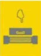 | Entrance&Exit of the Device inspection tunnel |
 | ||
| Forklift |  | Forklift entry point on the Device enclosure. |
| Watch your hand. |  | Surface of the conveyor cover |
 | ||
| This product and - if applicable - the supplied accessories too are marked with "CE" and comply therefore with the applicable harmonized European standards. |  | Outer box label and nameplate. |
| 2012/19/EU (WEEE directive): Products marked with this symbol cannot be disposed of as unsorted municipal waste in the European Union. For proper recycling, return this product to your local supplier upon the purchase of equivalent new equipment, or dispose of it at designated collection points. |  | Outer box label and nameplate. |
| For more information see: http://www.recyclethis.info. |
Table of Contents
Foreword.... I
Important Safeguards and Warnings.... III
Part1: Product Introduction .... 1
1 Overview.... 1
1.1 Introduction....1
1.2 Functions....1
1.3 Packing List....2
2 Dimensions and Structure .... 3
2.1 Dimensions....3
2.2 Cable Ports 4
2.3 Indicators....5
Part2: Operator....6
3 Display and Control....6
3.1 Emergency Stop Button and Indicator 6
3.1.1 Emergency Stop Button 6
3.1.2 Power Indicators....6
3.1.3 X-Ray Indicator....6
3.1.4 Power Input....7
3.2 Operation Keyboard....8
3.2.1 Control Keys....8
3.2.2 Function Keys....10
3.2.3 Image Processing Keys....12
3.3 Simple Operation Keyboard....13
3.3.1 Control Keys....14
3.3.2 Function Keys....14
3.3.3 Image Processing Keys....17
4 Basic Operations.... 20
4.1 Power on....20
4.2 Login and Logout....20
4.2.1 Logging in....21
4.2.2 Logging out 22
4.3 Warming up....22
4.4 Object Placement....24
4.5 Object Scanning 24
4.6 Shut down 25
4.7 Basic Information Search....25
4.7.1 Baggage Search....25
4.7.2 Report Search....28
5 Image Processing and Live view.... 30
5.1 Live view....30
5.2 Security Screening Mode....30
5.3 Image Processing....34
5.3.1 Image Enhancement .... 34
5.3.2 Image Correction 44
5.3.3 Force Scan....45
5.4 Monitoring Mode....45
6 Maintenance 47
6.1 Cleaning External Surface of the Device 47
6.2 Cleaning IR sensor on conveyor side 47
6.3 Cleaning Display Screen....48
6.4 Inspecting Conveyor....48
6.5 Inspecting Lead Curtain at the Tunnel Inlet and Outlet 48
6.6 Inspecting X-ray and Power Indicator 48
6.7 Emergency Stop Button 48
7 FAQ 49
7.1 When the key switch is turned on and the power button is pressed, the indicator doesn't work and the Device cannot be powered on....49
7.2 No generated images on the display screen 50
7.3 Conveyor doesn't work....50
7.4 Device automatically power off during running....51
Part3: Administrator 52
8 Daily Operations.... 52
8.1 Basic Settings....52
8.1.1 Initialization Device....52
8.1.2 Quick Configuration....55
8.2 Login and Logout....56
8.2.1 Logging in to Local Interface....57
8.2.2 Logging in to Web Interface ....58
8.2.3 Logging out ....59
8.3 Baggage Statistics....59
8.3.1 Baggage Search....59
8.3.2 Report Search....61
8.3.3 Voice Broadcast....62
8.3.4 Configuring Detection Parameters....65
8.3.5 Configuring Suspect Item....66
8.3.6 Security Screening....68
8.4 Video Playback....70
8.4.1 Playback ....70
8.4.2 Clipping Recording ....74
8.4.3 Image Playback....74
8.4.4 Exporting Files ....77
9 Settings 79
9.1 Device Management....79
9.1.1 Managing the Device....79
9.1.2 Managing Camera....81
9.2 Network Management....107
9.2.1 Modifying IP Address....107
9.2.2 Setting Port Number 109
9.2.3 Configuring Email....110
9.2.4 Setting SWITCH....112
9.2.5 Configuring Auto Register....113
9.2.6 Configuring UPnP 114
9.3 Storage Management....115
9.3.1 HDD....115
9.3.2 RAID Management....119
9.4 Event 124
9.5 System....126
9.5.1 Setting System Parameters 127
9.5.2 Setting Time....128
9.5.3 Display Output....129
9.5.4 Setting Schedule....131
9.6 Account Management 132
9.6.1 User Group 133
9.6.2 User Permission 135
9.6.3 User 137
9.6.4 ONVIF User 141
9.7 Security Management....144
9.7.1 Setting IP Access Authority 144
9.7.2 Setting Safety Protection 146
9.7.3 Setting System Service 147
9.7.4 Setting Firewall....148
9.7.5 HTTPS....148
10 Operation and Maintenance Management 154
10.1 Log Search....154
10.1.1 System Log....154
10.1.2 User Operation Log....155
10.1.3 Event Log.... 155
10.1.4 Link Log....156
10.2 Online User....157
10.3 Maintaining Device....158
10.3.1 Upgrade 158
10.3.2 Factory Default....160
10.3.3 Configure and Backup....160
10.4 Notification Center....161
10.5 Device Diagnosis....162
10.5.1 X-ray System Diagnosis....162
10.5.2 IR Sensor Diagnosis 163
10.5.3 Special Keyboard Diagnosis....164
10.5.4 One-Click Diagnosis.... 165
10.6 Logout/Rebooting/Shutting 166
11 FAQ2.... 168
11.1 The conveyor works normally, but the baggage image is not generated.... 168
11.2 The conveyor suddenly stops during the working process.... 169
11.3 No AI overlay after scanning baggage....170
Appendix 1 Dimension Diagram of Applicable Models.... 172
Appendix 2 RAID 175
Appendix 3 Total HDD Capacity Calculation .... 177
Appendix 4 Cybersecurity Recommendations....178
Part1: Product Introduction
1 Overview
1.1 Introduction
The intelligent AI dual-energy security screening machine is a new security screening device that uses X-ray to quickly inspect baggage and goods without opening the packages. The Device adopts advanced X-ray image detection system, with efficient semiconductor detector, digital image processing technology, and computer image display technology, to provide users with an efficient, reliable and high-quality image processing system with service functions. The Device has a large HDD capacity that can store no less than 1 million high-definition images, with reliable intelligent recognition and alarm against prohibited goods, person-package linkage, image enhancement, network expansion and interconnection, automatic detection and maintenance, and other functions. In addition, its simple and user-friendly operation design makes the user operation more convenient and efficient.
It is mainly used in the security screening in various scenes such as airports, railway stations, bus stations, subway rail transit, government office buildings, convention and exhibition centers, and large-scale events.
1.2 Functions
● Support using X-ray to generate images of packaged items passing the conveyor, and check
- Support displaying images of the packages with enhanced effects, such as penetration enhancement, super enhancement and high density alert.
● Support dual-screen display. Security screening mode and monitoring mode are selectable.
- Support analyzing the scanned image, AI recognize the prohibited objects such as knife, liquid, spray-can, gun, lighter.
- Support setting danger level for prohibited objects and can be linked with voice prompts, sound and light alarms, conveyor stop, and more.
● Support AI overlay on suspect objects. The AI overlay square moves with the package.
- Support storage of all test results and statistics into reports, which can be queried and exported through different categories and time periods.
● Support adding IP camera and PoE camera to monitor the entire security screening process.
- Support system abnormal alarm (including no HDD, storage failure, IP conflict, MAC conflict, and more).
● Support HDD storage space management, RAID creation, and more.
● Support management of individual users and user groups.
- Support system operation and maintenance management, such as searching log and online user search, and upgrading device.
1.3 Packing List
Refer to the following checklist to check the package. If you find device damage or component loss, contact the after-sales service.
Table 1-1 Checking list
| No. Item Description | |||
| 1 | Overall packing | Appearance Obvious damage | |
| Packaging Accidental impact | |||
| Accessories (see packing list) | Complete or not | ||
| 2 | Main body | Appearance Obvious damage | |
| Model | Whether consistent with the order contract | ||
| Labels on the Device | Whether the labels are torn off.Do not tear off and discard the labels. Or the warranty to this Device will be compromised. You might be asked to provide the serial number of this Device when you call the after-sales service. | ||
2 Dimensions and Structure
2.1 Dimensions
Figure 2-1 AI dual-energy security screening machine (mm [inch])
![4420.0[174.02°] 2319.0[91.30°] 1420.0[58.66°] 1294.0750.94° 955.0[37.60°] 654.0[25.75°] 1423.0750.24° 455.0[19.88°] 453.0[26.10°]](/content/2026/05/996920/images/d2b8c0d4591a46a8fd0d5de8fcbfbe98865c757acd27b2e0fdc0b244a9ace7f0.jpg)
Figure 2-2 Console (mm [inch])


This section takes ISC-M6550D as an example. For the details of other models, see Appendix 1.
2.2 Cable Ports
Figure 2-3 Cable ports
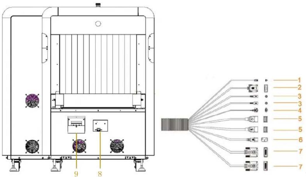
Table 2-1 Description of External Cable Connection
| NO. | Port Name | Description | Model |
| 1 | Network cable | Connect the Device to the Internet. | ALL |
| 2 | Serial port cable | Connect the operation keyboard. | ALL |
| 3 | Audio cable | Connect the audio output device. | ALL |
| 4 | Alarm indicator cable | Connect the alarm indicator device. | ALL |
| 5 USB | cable | Connect to mouse, keyboard, USB storage devices, and more. | ALL |
| 6 | Console power supply cable | Connect the terminal board of the console to supply power for it. | ALL |
| 7 | DVI video output cable | Connect the output display. | Security screening machine 6040/5030 only has 1 DVI video output cable. |
| 8 | Power port | Connect the power cable. | The position of the power port varies from different security screening machines, which prevails the real equipment. |
| 9 Fuse | The fuse and circuit breaker is on when it is in up position. The Device can be normally powered on only when the circuit breaker is turned on. | The position of the fuse varies from different security screening machines, which prevails the real equipment. |

In Figure 2-1, applicable model series are as follows: ISC-M100100D/ISC-M100100/ISC-M6550-V/ISC-M6550/ISC-M6040/ISC-M5030.
ALL means all models are applicable.
2.3 Indicators
See Figure 2-4, indicators on one side of the Device body as follows. And the other side is the same.
Figure 2-4 Indicators (One side)

There are four X-ray indicators (red) on the upper part of the Device. In working status, the red indicators are on when X-ray is triggered; the indicator lights are off when X-ray is turned off.
There are four power indicators (green) on the lower part of the Device. When the Device is started, the green indicators are on; when the Device is upgraded or fails, the green indicators flash.

Figure 2-4 takes Model ISC-M6550D as an example. The height of the indicators varies from models, but all are above the conveyor and around the Device main body.
Part2: Operator
3 Display and Control
3.1 Emergency Stop Button and Indicator
3.1.1 Emergency Stop Button
Figure 3-1 Emergency stop button


3.1.2 Power Indicators
The power indicator shows whether the power of the Device is turned on. If the POWER green indicator is on, it indicates the power of the Device is connected.
Figure 3-2 Power indicator

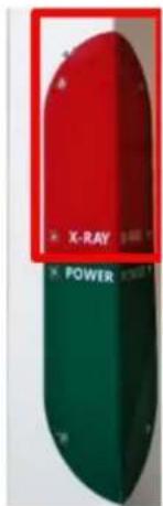
3.1.3 X-Ray Indicator
X-Ray Indicator is used for warning and displaying the X-Ray emission. If the X-Ray red indicator is on, it indicates X-Ray is emitting.
Figure 3-3 X-ray indicator
3.1.4 Power Input
After the Device is connected to the power supply, dial the circuit breaker upwards to power on the Device.
Figure 3-4 Power input

natural_image
Interior view of a black-framed room with a blue industrial machine display (no visible text or symbols)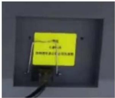
3.2 Operation Keyboard
Figure 3-5 Keyboard
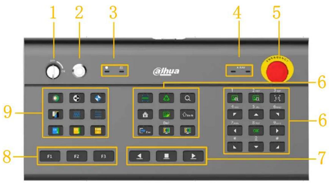
3.2.1 Control Keys
Table 3-1 Special Keyboard Description
| NO. Name | Description | |
| 1 | Key switch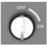 | It is used to power on the device control system, and prevent anyone other than the operator from operating the Device.Turn the switch clockwise to the "ON" state to power on the control system. At this time, the green power indicator (the left indicator of 3 in the picture) is on, but the industrial PC and X-ray generator are not powered on.Turn the key switch counterclockwise to the "OFF" state, the software exits, industrial PC powers off and the system power supply is disconnected.The key cannot be removed unless it is in the "OFF" position. |
| 2 | Start key | When the key switch is in the "ON" position, press this key to power on and start the system, and the green light is on. |
| 3 | Status indicator | It is used to indicate the keyboard working status after the system is started, including working status indicator and button indicator.Working status indicator (left): When the indicator is on, it indicates that the key has been turned on and the Device has been powered.Button indicator (right): When a key on the keyboard is pressed, a command is sent to the main control. The indicator flashes green once in normal operation; the blue indicator keeps on when the keyboard communication is abnormal. |
| 4 | X-ray indicators (2)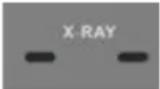 | When X-ray is triggered, two red X-ray indicators are on at the same time, which means that the X-ray is being emitted.For a dual-view device, the first indicator (left) indicates the main view X-ray generator, and the second indicator (right) indicates the profile view X-ray generator. |
| 5 | Emergency stop button | After pressing this button, the X-ray generator on the Device and the conveyor are stopped and powered off immediately.After releasing the button, you need to manually restart the conveyor. |
| 6 Function keys | For details of function keys on the special keyboard, see 3.2.2 Function Keys. | |
| 7 Conveyor control keys | :  rollers left . When the rollers are rotating forward, press the reverse rotation key to stop the conveyor. rollers left . When the rollers are rotating forward, press the reverse rotation key to stop the conveyor. the rollers. the rollers. : Rotate the rollers right. When the rollers are reversely rotating, press the forward rotation key to stop the conveyor. : Rotate the rollers right. When the rollers are reversely rotating, press the forward rotation key to stop the conveyor. | |
| 8 Custom function keys | Default function shortcutsF1: LightF2: DarkF3: High penetration You can set different functions for F1, F2, and F3 as required.See 3.2.3 Image Processing Keys for operation bar configuration.In the live view pop-up window, F1 is OK, and F2 is Cancel. You can set different functions for F1, F2, and F3 as required.See 3.2.3 Image Processing Keys for operation bar configuration.In the live view pop-up window, F1 is OK, and F2 is Cancel. | |
| 9 | Image processing keys | For details of function keys on the special keyboard, see 3.2.3Image Processing Keys. |
3.2.2 Function Keys
For details of function keys, see Table 3-2.
Table 3-2 Description of function keys
| Keys Function Description | ||
 | Force scan | Disabled by default.● Force scan is for detection of ultra-thin objects. After force scan is enabled, the X-ray works continuously once the conveyor is started.● After force scan is disabled, the X-ray is triggered only when the conveyor is started and an object passes the IR sensor. |
 | Power saving (optional) | Disabled by default.● When the system is ready, press this key, and the prompt of Power saving mode is enabled will pop up at the upper-right corner of the screen.◇ When the baggage blocks the power saving sensor, the system starts normal scan, and the real-time image is displayed.◇ If no passing object is detected by the model of power saving sensor within 15s, the conveyor will automatically stop to avoid idling without baggage, thus saving power.● Then press this key again, the prompt of Power saving mode is disabled will pop up at the upper-right corner of the screen, and the Device returns to normal.● When the power saving mode is enabled and the conveyor stops, Press the conveyor control button to start it. If no passing object is detected within 15s, the conveyor will stop again. |
 | Digital Zoom | If there are relatively thin or small objects that are not easy to recognize in the scanned image, you can use this function to zoom in a local region of the scanned image. There is a fixed square area, move the square to the image, the image inside the square will be enlarged for operators to further confirm the details.● Press this key for the first time to enable digital zoom with 2x zoom times.● Press this key for the second time to enable digital zoom with 4x zoom times.● Press this key for the third time to disable digital zoom. |
 | Menu | Press this key on any menu interface to switch to the main menu interface. |
 | Image management | Press this key on any menu interface to switch to the baggage search interface. |
 | Function switch | Numeric keyboard is for number by default. Press this key to switch among numbers, lowercase letters, and uppercase letters in sequence.[IMAGE]Shift does not affect the input state of the local virtual keyboard of the server. |
 | Exit | Press this key on any menu interface to switch to the live view interface. Exit all image enhancement states and effects of zooming in and zooming out (the default state is a color image with 1x zoom multiple) |
 | Previous Bag | The previous image playback ends once the conveyor is restarted.● Click the key to see the previous image with fixed speed.● Click and hold for continuous playback. |
 | Next Bag | The next image playback ends once the conveyor is restarted.● Press this key to play back the next image.● Press and hold this key to quickly play back next images. |
 / / | Zoom in/out | Zoom in and out on the image with the default max zoom times of 8x, which can be modified to 64x.● After zooming in, the zoom times are displayed in the status bar, at the same time, the focus of the current zoomed-in region (the red square circled area) is displayed on the small map in the lower left corner.● After zooming in, you can move the focus position by pressing the direction keys on the keyboard, dragging the red square circled area on the small map, or dragging the image of real-time baggage area. The image of real-time baggage area can only be dragged when the conveyor stops.● You can drag the image border with the mouse or scroll the wheel to zoom in or out on the image. |
 | Normal (screen adaptation) | If the image display is not 1x, press this key to change the image display scale to the original scale 1:1. |
1 2ABC 3DEF  | Direction keyboard / numeric keyboard | After zooming in, you can use these buttons to adjust the position of the zoomed-in region, including eight directions: Top left, bottom left, top right, bottom right, up, down, left, right.In text box, you can enter the corresponding numbers, uppercase and lowercase English letters by pressing 0–9 keys on the corresponding numeric keyboard. As is shown in the left picture.In text box, after enter shift, 0 key on the numeric keyboard can be used as a space.OK key: When F1 is used as the OK key, the function is the same as F1. |
3.2.3 Image Processing Keys
After an image processing key is triggered, the corresponding processing result of the current image is displayed in the status bar. For details of image processing keys, see Table 3-3.
Table 3-3 Description of image processing keys
| Keys Function Description | ||
 | Color/Black & white | Switch between color display and black & white display. Press this key once to display the image in black & white; Press it again to display the image in color. |
 | Inverse Color | Enable/disable image inverse color. Press this key once to achieve inverse color; press it again to exit the inverse color. |
 | Super Enhancement | Enable/disable super image enhancement. Press this key once to start super enhancement; press it again to exit super enhancement. |
 | Image Scan | It's used for displaying the result of scanned images under different absorption rate.Press this key for the first time, and the absorption rate starts to decrease to the minimum value, and then starts to increase to the maximum value, for cycle display.Press this key for the second time to stop the image transformation effect.Press this key for the third time to exit the image scan state. |
 | High Penetration | Enable/disable high penetration. Press this key to enable high energy image processing. |
 | Low Penetration | Enable/disable low energy enhancement. Press this key to enable high energy image processing. |
 | Organic Stripping | Enable/disable the image function of organic stripping. Press this key to enable the image processing function of organic stripping; press it again to exit the function. |
 | Inorganic Stripping | Enable/disable the image function of inorganic stripping; press this key to enable the image processing function of inorganic stripping; press it again to exit the function. |
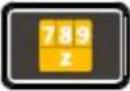 | Density Threat Alert | Press this key for the first time, substance with effective atomic number Z_eff = 7 highlights in red.Press this key for the second time, substance with effective atomic number Z_eff = 8 highlights in red.Press this key for the third time, substance with effective atomic number Z_eff = 9 highlights in red.Press this key for the fourth time to exit Density Threat Alert.If you press ESC during this process, it is restored to the default color image effect. |
3.3 Simple Operation Keyboard

3.3.1 Control Keys
Table 3-4 Simple Operation Keyboard Description
| NO. Name Description | ||
| 1 Function keys | For details of function keys of special keyboard, see 3.2.2Function Keys. | |
| 2 | Conveyor control button |  Rotate the rollers left. When the rollers are rotating forward, press the reverse rotation key to stop the conveyor. Rotate the rollers left. When the rollers are rotating forward, press the reverse rotation key to stop the conveyor. : Stop rotating the rollers.: : Stop rotating the rollers.:  Rotate the rollers right. When the rollers are reversely rotating, press the forward rotation key to stop the conveyor. Rotate the rollers right. When the rollers are reversely rotating, press the forward rotation key to stop the conveyor. |
| 3 Custom function keys | Default function shortcutsF1: LightF2: DarkF3: High penetration You can set different functions for F1, F2, and F3 as required.See 9.5.3Display Output for operation bar configuration.In the live view pop-up window, F1 is OK, and F2 is Cancel. You can set different functions for F1, F2, and F3 as required.See 9.5.3Display Output for operation bar configuration.In the live view pop-up window, F1 is OK, and F2 is Cancel. | |
| 4 | Image processing keys | For details of function keys on the special keyboard, see 3.3.3Image Processing Keys. |
3.3.2 Function Keys
For details of function keys, see Table 3-5.
Table 3-5 Description of function keys
| Keys Function Description | |||
 | Digital zoom | If there are relatively thin or small objects that are not easy to recognize in the scanned image, you can use this function to zoom in a local region of the scanned image.There is a fixed square area, move the square to the image, the image inside the square will be enlarged for operators to further confirm the details.Press this key for the first time to enable digital zoom with 2x zoom times.Press this key for the second time to enable digital zoom with 4x zoom times.Press this key for the third time to disable digital zoom. | |
 | Menu | Press this key on any menu interface to switch to the main menu interface. | |
 | Image management | Press this key on any menu interface to switch to the baggage search interface. | |
 | Function switch | Numeric keyboard is for number by default. Press this key to switch among numbers, lowercase letters, and uppercase letters in sequence.Shift does not affect the input state of the local virtual keyboard of the server. | |
 | Exit | Press this key on any menu interface to switch to the live view interface. Exit all image enhancement states and effects of zooming in and zooming out (the default state is a color image with 1x zoom multiple) | |
 | New line | In the live view interface, press this key to jump to a new line. (In the web logging in interface, after enter the username, pressTabto jump to password line). | |
 | Delete | In the input interface, press the key to delete the input content. | |
 | Previous bag | The previous image playback ends once the conveyor is restarted.Press this key to see the previous image with fixed speed.Press and hold for continuous playback. | |
 | Next bag | The next image playback ends once the conveyor is restarted.·Press this key to play back the next image.·Press and hold this key to quickly play back next images. | |
 | Vertical flip | Press this key to flipped upside down the image on the screen. | |
 | Image correction | Press this key to correct the image. | |
 /_/ /_/ | Zoom in/out | Zoom in and out on the image with the default max zoom times of 8x, which can be modified to 64x.·After zooming in, the zoom times are displayed in the status bar, at the same time, the focus of the current zoomed-in region (the red square circled area) is displayed on the small map in the lower left corner.·After zooming in, you can move the focus position by pressing the direction keys on the keyboard, dragging the red square circled area on the small map, or dragging the image of real-time baggage area. The image of real-time baggage area can only be dragged when the conveyor stops.·You can drag the image border with the mouse or scroll the wheel to zoom in or out on the image. | |
 | Normal (screen adaptation) | If the image display is not 1x, press this key to change the image display scale to the original scale 1:1. | |
 | Direction keyboard | After zooming in, you can use these buttons to adjust the position of the zoomed-in region, including four directions: up, down, left, right. | |
 | Numeric keyboard | In text box, you can enter the corresponding numbers, uppercase and lowercase English letters by pressing 0–9 keys on the corresponding numeric keyboard. As is shown in the left picture.In text box, after enter shift, 0 key on the numeric keyboard can be used as a space.Enter: When F1 is used as the OK key, the function is the same as F1. | |
3.3.3 Image Processing Keys
After an image processing key is triggered, the corresponding processing result of the current image is displayed in the status bar. For details of image processing keys, see Table 3-6.
Table 3-6 Description of image processing keys
| Keys Function | Description | |
 | Color/Black & white | Switch between color display and black & white display.Press this key once to display the image in black & white;Press it again to display the image in color. |
 | Inverse color | Enable/disable image inverse color. Press this key once to achieve inverse color; press it again to exit the inverse color. |
 | Super enhancement | Enable/disable super image enhancement. Press this key once to start super enhancement; press it again to exit super enhancement. |
 | Image scan | It's used for displaying the result of scanned images under different absorption rate.Press this key for the first time, and the absorption rate starts to decrease to the minimum value, and then starts to increase to the maximum value, for cycle display.Press this key for the second time to stop the image transformation effect.Press this key for the third time to exit the image scan state. |
 | High Penetration | Enable/disable high penetration. Press this key to enable high penetration. |
 | Low Penetration | Enable/disable low penetration. Press this key to enable low penetration. |
 | High density alert | Enable/disable high density alert. Press this key to enable high density alert. |
 | Pseudo color | Enable/disable image pseudo color.Press this key to enable pseudo color; press it again to exit the function. |
 | Edge enhancement | Enable/disable the image function of edge enhancement.Press this key to enable edge enhancement; press it again to exit the function. |
 | Light | Enable/disable light.Press this key to enable light; press it again to exit the function. |
 | Dark | Enable/disable dark.Press this key to enable dark; press it again to exit the function. |
 | Organic Stripping | Enable/disable the image function of organic stripping.Press this key to enable the image processing function of organic stripping; press it again to exit the function. |
 | Inorganic Stripping | Enable/disable the image function of inorganic stripping; press this key to enable the image processing function of inorganic stripping; press it again to exit the function. |
 | Mixture Stripping | Enable/disable mixture stripping. Press this key to enable mixture stripping. |
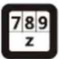 | Density Threat Alert | ● Press this key for the first time, substance with effective atomic number Z_eff = 7 highlights in red.● Press this key for the second time, substance with effective atomic number Z_eff = 8 highlights in red.● Press this key for the third time, substance with effective atomic number Z_eff = 9 highlights in red.● Press this key for the fourth time to exit Density Threat Alert.If you press ESC during this process, it is restored to the default color image effect. |

M5030/M6040 uses Simple Operation Keyboard.
4 Basic Operations
You must initialize the Device for first-time use, and do some basic settings such as data collection, display, and inspection.
4.1 Power on
Before powering on this Device, finish the connection of all cables. For details, see 2.1.2 Cable Ports.
Insert the plug of the power cable of the Device into the power supply socket to ensure that the power supply is normal.
After connecting the power cable, turn on the power switch (turn the circuit breaker upwards) to supply power for the Device.
Insert the key into the key socket in the upper left corner of the operation keyboard, (model 5030 and 6040 have their key socket on their machine upper enclosures) Turn the key clockwise to the position "ON", and the indicator on the right side of the key switch will light up.
When the key switch is ON, press the start key on the right side of the key switch to power on and start the system, the green indicator will be on and the Device will be powered on. The login in interface displays after the system startup animation ends.
After turning off the Device through soft shutdown (the key switch on the operation keyboard is "ON"), press the start button on the operation keyboard to turn on the Device.
WARNING
- Please make sure that the power cable has been connected to a power output socket with a protective grounding connection.

- Before starting the Device, make sure that the supply voltage input meets the power supply requirements.
- In order to ensure the stable operation of the equipment and prolong the service life of the hard disk drive (HDD), we recommend you to refer to international standards and provide a power input with stable voltage value and low ripple interference; if the power supply is unstable, it is recommended to add a UPS.
- To ensure the safety of the Device, connect the other cables of the device before turning on the power.
4.2 Login and Logout
This section introduces how to log in and log out in the case of one or two display monitors:
- Logging in to Local Interface: For first-time login or switching to a new user account, login in on one monitor, and then the other monitor logs in simultaneously. The settings interface can only be entered on monitor1.
- Log out: Log out on one monitor and the other monitor logs out simultaneously.
4.2.1 Logging in

By default, live view is only allowed after login in. If Live View Control is enabled in System
Settings > System Settings, the Live View interface can be displayed without login in.
This manual uses the default setting as the example.
Step 1 Power on the Device.
Figure 4-1 Local login

Step 2 Enter the username and password.

The operator enters operator's username and password.
Step 3 Click Login. The live view interface is displayed by default.
Figure 4-2 Local security screening interface

4.2.2 Logging out
At the lower-left corner of the live view interface admin, select the username in the login status, select Log out, and then the system returns to the login interface.
4.3 Warming up
The device will perform self-test to automatically determine whether warm-up is required every time when it is started. X-ray generator warm-up can gradually increase the operating voltage, thus ensuring normal operation of the generator and extending its service life.
Step 1 Log in to the system to perform self-test. If the Device is not used for a long time, the warm-up of the X-ray generator will be started.
Figure 4-3 Device warmup

Step 2 Clear the tunnel
- Click ▶/▶ or press ▶/▶ on the operation keyboard, and the conveyor moves to the left or right to convey the items in the tunnel.
- When all items are cleared from the tunnel, click □ or press □ on the operation keyboard to stop the conveyor.
Step 3 Click OK. Warm-up of the X-ray generator starts.
Warm-up time varies from the intervals between power off last time and power on this time. For more details, see Table 4-1.
Figure 4-4 Clear the tunnel

Table 4-1 Description of warm-up time
| Interval | Warm-up time |
| 0 Day < Y < 3 Days 0 minutes | |
| 3 Day < Y < 30 Days 5 minutes | |
| 30 Day < Y < 90 Days | 10 minutes |
| Y≥ 90 days | 50 minutes |
Step 4 The Image Correction interface is displayed after the warm-up ends.
Figure 4-5 Image correction

Step 5 Click Correction, the live view interface is displayed after image correction ends.

When the device is in normal use and the power-on interval does not exceed 3 days, the device is turned on normally. After the clear tunnel is displayed, directly enter the image correction interface in Figure 4-5. After the correction is completed, the live view interface is displayed (will not enter the warm-up process).
4.4 Object Placement
Inspected objects should be put stably on the conveyor or the roller table according to the object
placement sign

Figure 4-6 Object placement


Light and thin objects, dirty objects, or objects with damaged packaging need to be placed in a suitable plastic container for scanning.

WARNING
The inspected objects must be placed outside the lead curtain! It is strictly forbidden to reach into the detection tunnel!

Avoid falling or accumulating the inspected objects at the exit of the Device. Once it happens, stop the conveyor immediately.
4.5 Object Scanning
Step 1 After logging in, Device finishes the warm-up process. Start to scan the objects when it displays READY in the system status bar.
Step 2 After pressing or, conveyor starts to work. Place the inspected objects in the center of the conveyor and it will pass through the tunnel along the conveyor.
Step 3 According to the image of the inspected object, click the corresponding image function button on the operation keyboard to recognize image.
Step 4 After the inspected object is moved out of the tunnel along the conveyor, click on the keyboard to stop the conveyor. When inspection is done, the scanned objects can be taken out or further inspected.
4.6 Shut down

Before shutting, confirm that scanning is done and no objects in the tunnel.
Step 1 Click on the operation keyboard to confirm the conveyor has been stopped.
Step 2 When turning the key switch counterclockwise to the "OFF" state, the indicator on the right side of the key hole turns off, and the Device starts to shut down.

After step 1, you can use the lower-left corner of the live view interface to select the logged-in username, and select Shut to perform a soft shutdown of the Device. After the soft shutdown ends, you still need to go back to step 2.

As the Device needs to save scanned data and exit the operating system, do not immediately disconnect the external power supply of the Device.
Step 3 Disconnect the external power supply only after the indicators on the keyboard and on the body of the security screening machine are off and the shutdown is complete.
Step 4 Remove the key from the operation keyboard and keep it in a safe place.
4.7 Basic Information Search
4.7.1 Baggage Search
Search and count all scanned baggage, and view relevant videos.
Procedures
Step 1
Click

on the homepage.
The homepage is displayed.
Figure 4-7 Homepage

Step 2 Select BAGGAGE MANAGEMENT > BAGGAGE SEARCH.
Figure 4-8 Baggage search
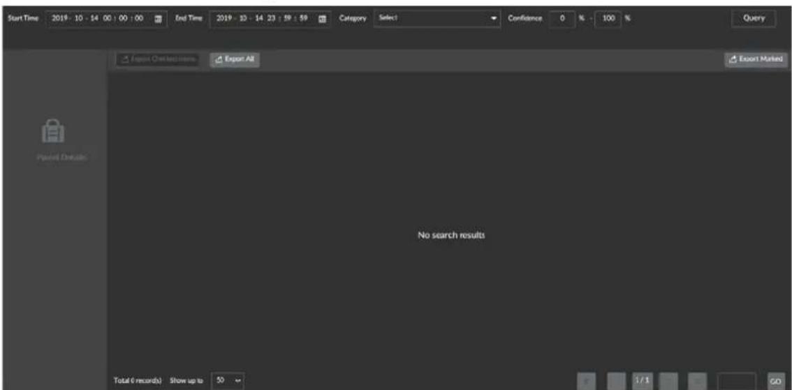
Step 3 Set the query period, select the Category, enter Confidence, and then click Query.

- The End Time must be later than the Start Time. The longest period for query is 30 days.
- The default category is All. Types of item include guns, explosives, knives, lighter, spray cans, liquid, electronic products, umbrellas, brass knuckles, handcuffs, nightsticks and uncategorized items.
Figure 4-9 Baggage search results: single view

Figure 4-10 Baggage search results: dual view


• Dual-view security screening machine: 2 channels display
- Single-view security screening machine: only single picture display
Step 4 View recordings: Select queried pictures and click ▶ on the left to play the recordings linked with the baggage 10s before and after the package passes the screening machine.

Prerequisite: The associated recording channel has been configured. For more details, see 8.3.6 Security Screening. The first installation is completed by administrator.
Step 5 View details: Click a queried picture and the system displays the baggage details.
Figure 4-11 Baggage details


Operator only has the access to Query and cannot Export. Once enter Export, it will display a prompt No access.
4.7.2 Report Search
Step 1 Select BAGGAGE MANAGEMENT > REPORT SEARCH
Figure 4-12 Report Search

Step 2 Set the query period, select the category of item, and then click Query.
Figure 4-13 Line chart

radar
| Category | Value | | -------------- | ----- | | Total Scissors | 300 | | Paints | 50 | | Handcoils | 50 | | Fireworks Plants | 50 | | Nightsticks | 50 | | Spray cans | 50 | | Brands/Crackies | 50 | | Grains | 50 | | Lighter | 50 | | Aero | 50 | | Tool | 50 | | Scissors | 50 | | Electronics | 50 | | Ignition oil | 50 | | Cell Phone | 50 | | Nut Polymers | 50 | | Power Bars | 50 | | Liquide | 50 | | Laptop | 50 | | Litter | 50 | | Umbrella | 50 | | Thermal Gas | 50 | | Undecaltered | 50 |Step 3 Click Data and the system displays data in the form of report.
Figure 4-14 Report
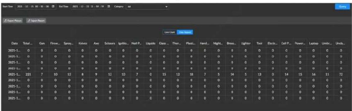

Operators only have the access to Query and cannot Export. Once enter Export, it will display a prompt No access.
5 Image Processing and Live view
5.1 Live view
The live view interface can be set as Security Screening Mode or Monitoring Mode as needed. For more details, see 9.5.3 Display Output. The mode is set by the administrator before the Device leaving the factory.
5.2 Security Screening Mode
After setting the prohibited items recognition strategy, you can view the detection images and snapshots of suspect items on the live view interface. The software interface has the same image and operation function icons as the operation keyboard, which achieves same functions. For more details, see 3.2.2 Function Keys and 3.2.3 Image Processing Keys.
Figure 5-1 Security Screening Mode

Table 5-1 Security screening mode interface description
| NO. | Name Description | |
| 1 | Scanned baggage record | Scroll display the scanned baggage, and the scan direction is from left to right regardless of baggage direction. Up to 100 records can be displayed.If there are multiple hazardous goods in the baggage, they will be displayed in red, purple or gray depending on the danger level. For more details abou danger level, see 8.3.4.2Configuring Suspect Item.Single-view device, one image per group. Dual-view device, two images per group.(display in main view + profile view)If there are duplicate contraban d in the baggage, the title name automatically cover the same item name. For example, if there are 2 knives, its name will only be displayed once, and only the serial number will be superimposed, such as suspect knife2 (89%). |
| 2 | Real-time baggage area | Scroll display the live scanning image from the Device. For more details, see Table 5-2. |
| 3 | Baggage thumbnail | The baggage thumbnail displays the position of the current preview screen in the overall screen.After overall zoom, the tracking square is used to display the position of the current screen in the overall area. The tracking square is red in the playback state, and blue in the real-time package scanning state. |
| 4 | Login user | Click this icon and you can modify user password, lock down user, log out, reboot or turn off the Device. |
| 5 | Baggage statistics | Display the number of temporary baggages(the statistics starts from the Device is powered on) or the number of cumulative baggages (the statistics starts from the Device leaves the factory). |
| 6 | Zoom in times | Display zoom in times. The default maximum zoom-in is 8 times, and the maximum zoom-in is 64 times. |
| 7 | Scan direction: | Display scan direction on the screen. It can be displayed by single direction or double direction. |
| 8 | Conveyor status | Display the current movement direction of the Device conveyor. |
| 9 | Device working status | It displays the working status of the Device (normal/fault).Preparation: Device powering on and warm upCorrection: Device correctionDiagnosis: Device diagnosingReady: When the software is running and the conveyor is not started,Readyis displayed. Meanwhile, if force scan is enabled,Ready[C] is displayed.Waiting for scanning: The rollers rotates, no baggage on the conveyor.Scanning: The rollers rotates and X-ray starts to scan the baggage.Continuous scanning: Force scan starts and the roller rotates.Stop: Stop the conveyor. |
| 10 | Image enhancement status bar | Display image enhancement status. When there is an fault of the Device function, the fault information prompt will be displayed. |
| NO. Name Description | ||
| 11 | System time | Display the current time of the operating system. |
| 12 Menu | Click this icon to enter the setting interface.Enter the setting interface, network, alarm, storage, user and basic system setting can be set.Enter the setting interface, click LIVE in the upper left corner to return to the live view interface. | |
| 13 Notification bar | Display the number of the notification. Click to see all the notifications.The button displays the total number of the current notifications. If the number is 0, the window is hidden.Click the notification bar to view all the notifications. You can also view three types of messages by classification (system error),(system warning),(system notification).After the notification bar is unfolded, it will retract if the cursor leaves for 3 s. Click the lock button to prevent the message bar from automatically retracting. You can manually close it by clickingClick to delete an alarm message. Click to clear all the notifications. | |
| 14 | Custom functions(F1/F2/F3custom function keys) | Click this icon to enhance the configured images. For details, see 9.5.3Display Output.This icon corresponds to the functions of F1, F2, and F3 keys on the keyboard. |
| 15 Previous and Next | You can view the last 30 baggage images after startup. Click the previous icon to see the previous image with fixed speed; Click the next icon to see the next image with fixed speed; Click and hold for continuous playback.This function can also be used by clicking keys on the operation keyboard. | |
| 16 AI overlay switch | Click this icon to enable/disable the AI overlay square of the prohibited objects, and configure whether to display item name, text background, and similarity. Click this icon to turn on/ turn off this function. | |
| 17 | Image enhancement button | Up to 12 image enhancement buttons are displayed on the interface by default. You can modify the display of buttons in the display output configuration. Default configurations: high penetration, light,dark, low energy enhancement, scanning, edge enhancement, super enhancement, color/ black & white, inverse color, organic stripping, vertical flip, image correction. For details, see 5.2Image Processing.Place the mouse cursor over the icon to display the corresponding function name. See 3.2.3Image Processing Keys.The display of image enhancement buttons is related to the screen resolution.1080P: 12 function icons are displayed in the same row on the interface.1280*1024: 12 function icons are displayed in two rows. The first six functions are displayed in order on the interface. Clickto pop up the list of the other six functions. |
| 18 | Conveyor control buttons | ● :  , rotates backward● : , rotates backward● :  . conveyor● : . conveyor● :  , rotates forward , rotates forward |
Figure 5-2 Notification bar

Figure 5-3 Image enhancement button(1080P)

natural_image
Row of ten application icons including camera, folder, lock, MS, and waveform display (no text or labels visible)Figure 5-4 Image enhancement button (1280*1024)

Table 5-2 Description of the real-time baggage area display
| Type Description | |
| Displayed content | For every suspect item, its type and confidence level are displayed by default.You can set whether to display the type and confidence level in AI Overlay. Clickto configure whether to display item name, text background and similarity,disabled by default. |
| Danger level | If several prohibited items exist in the same bag, the danger level is judgedaccording to the item with the highest danger level. For example, if a bag has bothhigh risk items and safe items, the bag image is displayed on the high risk area onthe left of the scanned baggage records.The background color of prohibited item images means the danger level:Red: High riskOrange: WarningDark gray: SafeLight gray: Uncategorized |
5.3 Image Processing
Image processing function area interface Image processing functions can be operated not only on the software interface, but also directly through the special keyboard of the Device.
Figure 5-5 Image enhancement

natural_image
Row of ten application icons including camera, folder, lock, MS, and weather symbols on a dark background (no text or labels)- Click an icon for the first time, the image is highlighted; click the icon again, the image is not highlighted. The image is colored by default.
- Image enhancement takes effects on the whole baggage area. All image enhancement functions take effects in the real-time baggage area whether the baggage normally passes or not.
- Image enhancement only takes effects for security screening mode. If the security screening mode is an auto mode, the image enhancement key takes effect. If it is custom mode (such as
black & white mode; custom mode can be set in the display output configuration), the image enhancement key does not take effect.
- Click to select image enhancement function, and click again to cancel the corresponding image enhancement functions. Image enhancement functions can also be canceled by ESC

on the operation keyboard.
5.3.1.1 Color/Black & white
The color images not only show the absorption of X-ray by substances, but also show the material composition of the substances. To better identify dangerous items, scanned objects will be categorized into organic substance, mixture and inorganic substance, and marked in orange, green and blue respectively according to their composition for easier recognition to operators.
The color image is a four-color image. The scanned objects are divided into four categories:
• Orange: Organic substance
• Blue: Inorganic substance
- Green: Mixture
- Black/Red: Object with uncertain material properties and generally impenetrable.

- The brightness of each color corresponds to the thickness and density of the substances. The thicker the substances and the greater the density, the darker the colors.
- Based on the effective atomic number, the objects are divided into organic substance (lower than 10), mixture (between 10 and 18), and inorganic substance (higher than 18).
The image is displayed in color by default. Click Color/Black & White icon or press 📄 on the special keyboard to switch between color image and gray image.
Figure 5-6 Comparison of color image and black & white image

natural_image
Illustration of a device's internal components with colored sections (no text or symbols)
natural_image
Cross-sectional diagram of a device showing internal components like battery, motor, and housing (no text or labels)Partial enhancement can brighten darker areas in the image, so that the objects hidden behind thick objects can be clearly displayed without affecting normal image areas.
In normal image display, click

to switch the image to partial enhancement state; click the
icon again to return the image to normal display state.
Figure 5-7 Color image/image partial enhancement (partial enhancement)

natural_image
Illustration of a multi-layered electronic device with colored components and connectors (no text or symbols)
natural_image
Illustration of a multi-layered electronic device with colored components and connectors (no text or symbols)Through super enhancement, the images of penetrable objects (such as clothing and silk threads) and impenetrable objects (such as thick metal plates and frozen products) can be clearly displayed on the screen at the same time. Even low-density materials (such as clothing) hidden between the metal plates are clearly visible.
As a comprehensive image processing function, super enhancement obtains the best contrast of each point in the image, the best image details and edge information through the calculation and statistics of the contrast of each small image area.
During image display, click the Super Enhancement icon or press on the special keyboard to enhance details of the image, so that the objects hidden behind thick objects can be clearly displayed. Click the icon or press the key to display the image in super enhancement state. Click the icon or press the key again (or press ESC) to end super enhancement.
Figure 5-8 Color image/image super enhancement (super enhancement)

natural_image
Exploded view diagram of a mechanical assembly with colored components (no text or labels)
natural_image
Diagram of a device's internal components with colored sections and tool bodies (no text or labels)Compared with the default original image effect, the edge enhancement function enhances the edges display in the image, especially the display of weak edges, making the structure and contour information in the image more prominent and clear.
During image display, click 📄 to enable edge enhancement. Click the icon or press the key again (or press ESC) to end edge enhancement.
Figure 5-9 Color image/Image edge enhancement

natural_image
Illustration of a mechanical assembly with colored components and labeled parts (no readable text or symbols)
natural_image
Illustration of a mechanical device with colored components and measurement markings (no readable text or symbols)5.3.1.5 Image Scan
Image scan function separately displays the details of objects with different material thicknesses in the image. After enabled, the function periodically changes the absorption rate of the object image to observe details of each part of the image, with a certain contrast reserved outside the range of absorption rate. You can observe the whole image of the scanned object at any level.

During image display, click the Image Scan icon or press image automatically changes among different absorption part of the image. The set level is 50 (cycle change within t
on the special keyboard, the
- Click the icon or press the key for the first time to start cycle change.
- Click the icon or press the key for the second time to stop cycle change.
- Click the icon or press the key for the third time to exit the image effect.
Figure 5-10 Color image/image scan

natural_image
Exploded view diagram of a mechanical assembly with colored components (no text or labels)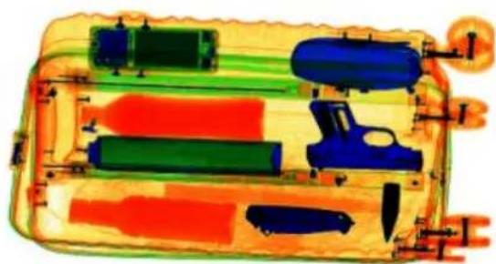
natural_image
Diagram of a device with colored components and connectors, no visible text or symbols5.3.1.6 Organic Stripping
Organic Stripping is often used for key inspections of inorganic substances and mixtures. Usually, prohibited metal tools such as knives and daggers are inorganic matters, while the mixing of such prohibited goods and daily necessities such as clothing and foods affects the judgment of the operator.
The organic substances' color is stripped and displayed in in black and white, while other substances (inorganic substances and mixtures) are displayed in colors that represent their material properties, so that inorganic substances and mixtures are clearly visible.
During image display, click the Organic Stripping icon or press on the special keyboard to highlight the blue parts (inorganic substances), without displaying the orange parts (organic substances), thus helping the operator to judge objects such as knives, guns, and gas cans.
Figure 5-11 Color image/Image organic Stripping

natural_image
Exploded view diagram of a mechanical assembly with colored components (no text or labels)
natural_image
Exploded view diagram of a mechanical device showing internal components like gears, cylinders, and housing (no text or labels)5.3.1.7 Mixture Stripping
This function is used for key inspections of organic substances and inorganic substances. The areas corresponding to mixtures in the color image are displayed in light gray, while other substances (organic substances and inorganic substances) are displayed in colors that represent their material properties, so that organic substances and inorganic substances are clearly visible.
During image display, click to highlight the blue parts (inorganic substances) and the orange parts (organic substances), without displaying the green parts (mixtures), thus helping the operator to judge objects.
Figure 5-12 Color image/Image mixture stripping

natural_image
Illustration of a multi-layered mechanical or electronic component with colored parts and connectors (no text or symbols visible)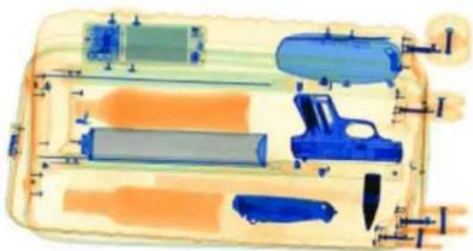
natural_image
Exploded view diagram of a mechanical assembly with components like rollers, gun, and tools (no text or labels)
The picture is for reference only. In actual mixture stripping, the green parts are stripped.
5.3.1.8 Inorganic Stripping
This function is often used for key inspections of organic substances and mixtures. Usually, hazardous goods such as drugs and explosives and daily necessities such as clothing and food belong to organic substances, while the inspected objects mixing such organic substances and thick knives or metal electrical products can be considered as mixtures.
The inorganic substances' color is stripped and displayed in black and white, while other substances (organic substances and mixtures) are displayed in colors that represent their material properties, so that organic substances and mixtures are clearly visible.
During image display, click the Inorganic Stripping icon or press on the special keyboard to highlight the orange parts (organic substances), without displaying the blue parts (inorganic substances), thus helping the operator to judge objects such as flammable materials such as explosives, drugs, and gasoline.
Figure 5-13 Color image/Image organic stripping

natural_image
Two technical diagrams showing internal components of a device, with no visible text or symbols.5.3.1.9 Inverse Color
Inverse color function is used to check thin high-density objects (such as metal wires) with an effect similar to the negative film. The function displays objects with high absorption rate in bright colors and objects with low absorption rate in dark colors without changing the current color tone.
During image display, click the Inverse color icon or press 📋 on the special keyboard, to display objects with high X-ray absorption rate in bright white and objects with low X-ray absorption rate in dark black, making small or thin high-density objects (such as metal wires) more clearly visible. It is the opposite in white inverse display.
Figure 5-14 Color image /Image inverse color

natural_image
Illustration of a multi-layered electronic device with colored components and connectors (no text or symbols)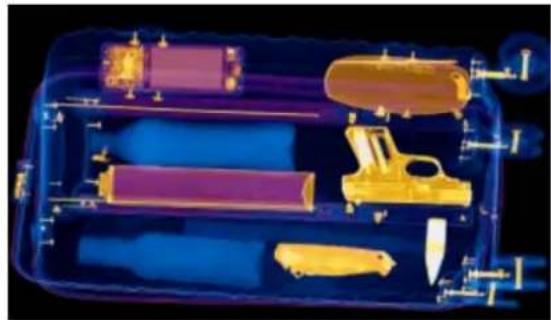
natural_image
Cross-sectional diagram of a mechanical device with labeled parts (no text or symbols visible)5.3.1.10 High Penetration
The function of high penetration is used to highlight details in the dark areas of the image. These dark areas correspond to impenetrable substances with high X-ray absorption rate, which usually have high density (such as lead and steel) or large thickness.
This function helps to analyze details in the dark areas of the image, so that hazardous goods hidden inside impenetrable objects can be inspected, while penetrable objects are hidden or faintly displayed.
During image display, click the High Penetration icon or press 📄 on the special keyboard to enable this function.
Figure 5-15 Color image/high penetration

natural_image
Two technical diagrams showing internal components of a device with colored sections and labeled parts (no readable text or symbols)5.3.1.11 Low Penetration
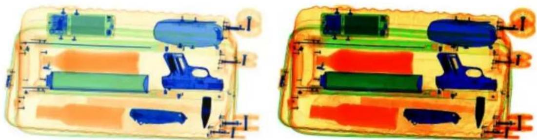
The function of low energy enhancement is used to highlight details in the bright areas of the image. These bright areas correspond to penetrable substances with low X-ray absorption rate, which usually have low density or small thickness, such as clothing and papers.
The function of low energy enhancement helps to analyze details in the bright areas of the image, so that penetrable objects are clearer and easy to recognize, while objects with high absorption rate are displayed in black.
During image display, click the Low Penetration icon or press on the special keyboard to enable this function. However, the normal areas are affected with reduced contrast.
Figure 5-16 Color image/low energy enhancement
natural_image
Two technical diagrams showing internal components of a device, with no visible text or symbols.5.3.1.12 Light/Dark
During image display, click + or - to lighten or darken the entire image. Click the icon again to restore normal image display.
Figure 5-17 Color image/light

Figure 5-18 Color image/dark

natural_image
Illustration of a multi-layered cylindrical device with internal components and mounting holes (no text or symbols)
natural_image
Diagram of a mechanical device with colored components and labeled parts (no readable text or symbols)5.3.1.13 Density Threat Alert Z7/Z8/Z9
The effective atomic number Zeff of explosives and drugs is relatively concentrated in the interval [7, 9]. For details, see Table 5-3.
Table 5-3 Description of effective atomic number of explosives and drugs
| Effective Atomic Number | Description |
| 7 Water and plastic explosives | |
| 8 Impure drugs or explosives. | |
| 9 Pure drugs | |
The function of density threat alert is used to further highlight organic substances with the effective atomic number Zeff = 7, 8 or 9. You can inspect organic substances with the effective atomic number Zeff = 7, 8 or 9 in turn. Other areas of the image are displayed in gray, and only the areas where the organic substances with the specified effective atomic number are located are displayed in bright red, for easy inspection of suspect explosives and drugs.
During image display, click the Density Threat AlertZ7/Z8/Z9 icon or press on the special keyboard to enable this function. Take Z7 effect as an example; for the image display effect, see Figure 5-19.
- Click the icon or press the key for the first time to display organic substances with the effective atomic number Zeff = 7 in red.
- Click the icon or press the key for the second time to display organic substances with the effective atomic number Zeff = 8 in red.
- Click the icon or press the key for the third time to display organic substances with the effective atomic number Zeff = 9 in red.
- Click the icon or press the key for the fourth time to disable the image enhancement effect.

Z7/Z8/Z9 state respectively corresponds to the highlighted number 7, 8, and 9 in the icon.
Figure 5-19 Color image/ density threat alertZ7/Z8/Z9

natural_image
Transparent plastic container with a textured circular pattern and small accessories (no visible text or symbols)5.3.1.14 High Density Alert
During image display, click the High Density Alert icon to display the impenetrable areas in the images of inspected objects in red.
Figure 5-20 Color image/high density alert for suspect image
natural_image
Illustration of a multi-layered electronic device with colored components and connectors (no text or symbols)
natural_image
Illustration of a mechanical assembly with colored components and labeled parts (no readable text or symbols)5.3.1.15 Zoom in/out
To display the image more clearly, you can use the global zoom function. This function can zoom in on the scanned image as a whole, so that the operator can carefully recognize every detail of the image.
During image display, click the Zoom in or Zoom out icon or press 📄/ 📃 on the special keyboard to zoom in or zoom out. For zoom-in display, see Figure 5-21.
After zooming in by using the global zoom function, use the mouse or press the direction keys on the special keyboard to drag the image for recognition. At the same time, there is a thumbnail of the zoomed image at the lower right corner. When zooming in, there is a black square that marks the image area currently displayed in full screen.
- You can scroll the mouse wheel to zoom in or out on the image.
- Smooth zoom in for each zoom-in, with up to 64x.
- Smooth zoom in for each zoom-in, with at least 1x.
- Press 📄 on the special keyboard for adapted screen display.
- When zooming in, press the direction keys of up ▲, down ▼, left ◀, right ▶, upper left ▶, lower left ▶, upper right ▼, and lower right ▶ on the special keyboard, and the image will automatically zoom in by 2x and move to the corresponding direction.
Figure 5-21 Zoom In

natural_image
Illustration of a vehicle's internal components and fuel system, showing battery, fuel tank, and gun (no text or labels)5.3.1.16 Pseudo Color
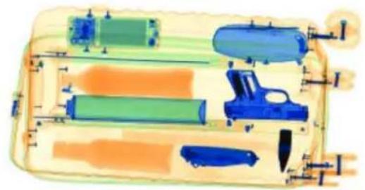
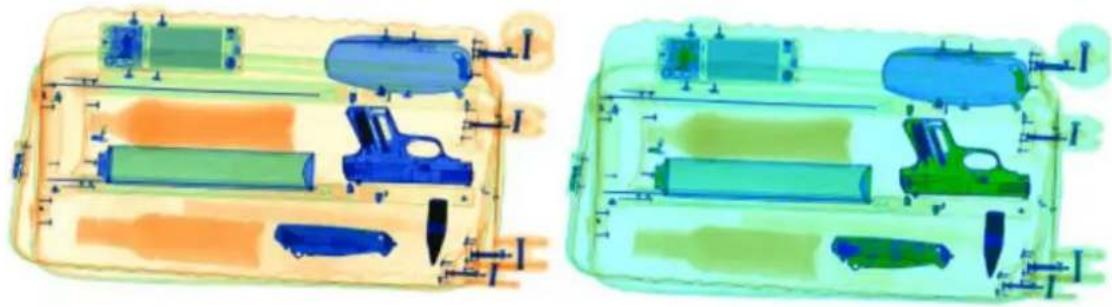
During image display, click 📄, and the image on the screen will change accordingly. The pseudo color image displays rich details, thus helping the operator to recognize details of the image. For the comparison of original image display and pseudo color display, see Figure 5-22.
Figure 5-22 Color image/pseudo color processing
natural_image
Two technical diagrams showing internal components of a device, with no visible text or symbols.5.3.1.17 Vertical Flip
During image display, click 📄, and the image on the screen is flipped upside down, thus helping the operator to recognize objects of different shapes. The vertical flip of screen 1 and screen 2 takes effect at the same time and cannot be separately set. That is, when you set flip on screen 1 or screen 2, it will take effect on both screens. For the comparison of original image display and vertical flipped display, see Figure 5-23.
Figure 5-23 Vertical flip

natural_image
Two identical technical diagrams showing internal components with colored blocks and labeled parts (no text or symbols present)5.3.1.18 AI Overlay
Click 📋 on the right side of the AI Overlay icon, and then select information to be displayed on the live view interface, including object name, text background, similarity, and package box. After selection, the corresponding information is displayed on the live view interface.
Figure 5-24 AI overlay setting
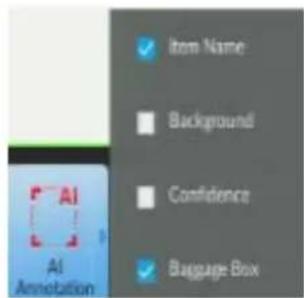
During image display, click the AI Overlay icon to enable this function to close the package box, object name, text background, and similarity on the live view interface. Click the icon again to disable this function and open information display on the live view interface.
Figure 5-25 AI overlay

5.3.2 Image Correction
During long-term and continuous scanning of scanned objects, the interval of which is too small (smaller than 20 cm), the image quality becomes poor due to minor changes in the parameters of the X-ray generator. Enable image correction to improve image quality.
During image display, click 📄 to correct the image. Click the icon again, and then select Continue Correction or Cancel in the prompt box.

- The correction process cannot be canceled upon the first startup, but can be canceled during normal use after startup.
- During correction, click the conveyor control button or the corresponding control key on the special keyboard to control the conveyor, ensuring that the tunnel is cleared.

During image correction, the system will automatically determine whether there are packages left in the tunnel. If yes, check the tunnel and ensure it is cleared before connection.
5.3.3 Force Scan

Disabled by default.
The function of force scan is used to detect and recognize ultra-thin objects.
Click Force Scan icon or press 📄 on the special keyboard to enable this function, the X-ray works continuously once the conveyor is started. Click the icon or press the key again to disable force scan. After the function is disabled, the X-ray is triggered only when the conveyor is started and an object passes the IR sensor.
5.4 Monitoring Mode
According to the settings of monitoring mode, live views of the linked channels are displayed.
Figure 5-26 Monitoring Mode

natural_image
Four-panel image showing a person in a lab setting, with film reel icons on the bottom panel (no text or symbols)- Manual snapshot: Point to the video window, and click 📄 to capture pictures.
- Manual recording: Point to the video window, click 📄 and the system starts recording. The length of the recording is displayed at the upper-left corner of the video window; click again and the recording stops.
6 Maintenance
Routine maintenance must be carried out during system operation in a prevention-oriented principle. It is one of the important links to use and operate the system in a reasonable manner.
6.1 Cleaning External Surface of the Device
During long-term operation of the Device, there will be dust and dirt on its external surface. To ensure normal operation, the external surface of the Device shall be regularly cleaned.
Use a slightly damp towel to clean the external surface of the Device.
Clean the enclosure and pole of the Device.

Before cleaning the external surface of the Device, you need to turn off the power and disconnect the Device from the external power supply.
6.2 Cleaning IR sensor on conveyor side
The IR sensor on conveyor side is blocked or clogged. After the conveyor ^③ is started, the Device immediately generates X-ray for scanning. Check the system settings, if Force Scan is not enabled, the IR sensor on conveyor side might be blocked or clogged.
Turn off the Device, and then remove the special keyboard key and carry it with you. Check the status of the IR sensor on conveyor side. The IR sensor is located on the inner wall① of the tunnel inside the lead curtain. Check whether the IR sensor is blocked, which affects its signal accuracy. You can gently clean the IR sensor surface with slightly damp cotton balls.
Figure 6-1 Clean IR sensor on conveyor side
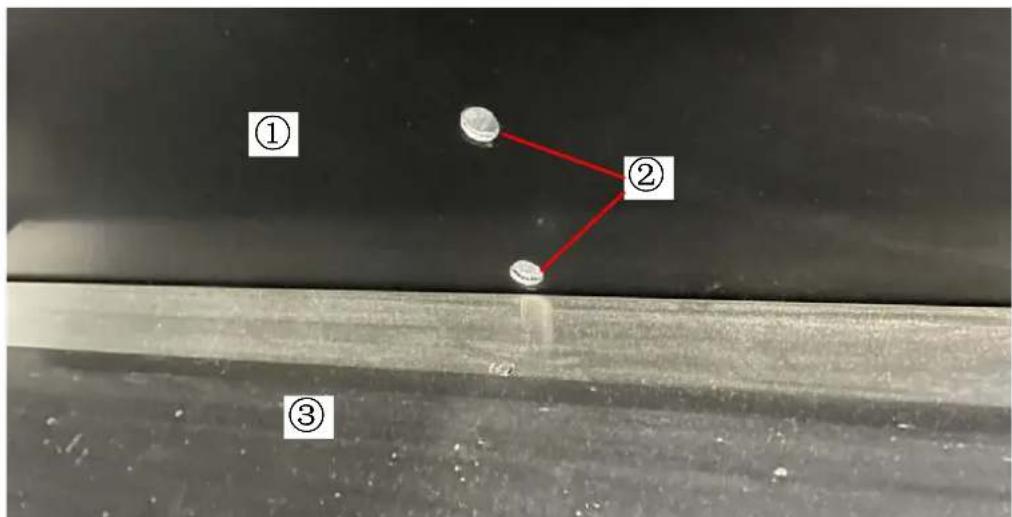
6.3 Cleaning Display Screen
During long-term operation of the Device, there will be dust or fingerprints on the display surface, affecting the resolution of the object image to be judged by the operator. You can use special detergent for display to clean the screen when the display is powered off and then adjust its brightness.
6.4 Inspecting Conveyor
During long-term inspection, the conveyor might deviate from the tunnel center. If the motor side is exposed due to the left or right deviation of the conveyor, the conveyor needs to be adjusted. Contact professional maintenance personnel to adjust the operation status of the conveyor, or carefully read the maintenance manual.
6.5 Inspecting Lead Curtain at the Tunnel Inlet and Outlet
If the lead curtain has large gaps, falls off or is damaged, contact professional maintenance personnel to replace or repair it.

The operator must wear gloves when adjusting the lead curtain.
6.6 Inspecting X-ray and Power Indicator
The system administrator and maintenance personnel can inspect the X-ray indicator status through corresponding operations in the diagnosis and maintenance program.
6.7 Emergency Stop Button
The emergency stop buttons on the Device enclosure and console are key safety Devices. If the switch is loose or the enclosure is damaged, immediately stop the Device, and contact professional maintenance personnel to maintain or replace the corresponding emergency stop button. The Device cannot be used until the button is repaired.

After repairing, press the emergency stop button. At this point, if the motor inside the system stops rotating and the X-ray generator stops generating X-ray, and a prompt showing that an emergency stop button is pressed is displayed, it means that the button works normally.
7 FAQ
7.1 When the key switch is turned on and the power button is pressed, the indicator doesn't work and the Device cannot be powered on.
Possible Cause
• The power cable plug of the Device is loose.
• The keyboard control cable plug is loose.
● The circuit breaker at the power input end is not closed or the fuse (circuit breaker) is open.
Troubleshooting Procedures
- Please first check whether the power cable plug of the Device has been inserted into the power socket normally or not. If the plug is loose, please reinsert it.
- Please check whether the keyboard control cable plug is loose or not. If there is a problem, please reinsert it and rotate the screws on both sides of the plug to make it firm.
- Rotate the key switch on the operation keyboard. If the indicator on the right lights up and the Device can be started, the fault is eliminated. If the fault is still not eliminated, follow the procedures below to settle it again.
- Use tools to open the enclosure where the circuit breaker and fuse are installed on the equipment, check whether the circuit breaker is off and whether the fuse is on. If the fuse is burned out, replace the Device with components of the same specification.
- Rotate the key switch on the operation keyboard again, if the indicator on the right is on, the Device can be started, and the fault is eliminated.
Figure 7-1 Troubleshooting


The position of the power supply and the circuit breaker vary from models. If the errors cannot be eliminated according to the above procedures, please contact professional maintenance personnel.
7.2 No generated images on the display screen
Possible Cause
● Power switch of the display screen is off;
- Cable plug is loose of the display screen;
- HDMI connection cable loose of the display screen.
Troubleshooting Procedures
- Please check the power switch of the display screen to confirm the switch is on and the indicator lights up at this time.
- Please check whether the display screen cable plug is loose or not. If there is a problem, please reinsert it and rotate the screws on both sides of the plug to make it firm.
- Observe the display screen, if the image is generated, the fault is eliminated.

If the errors cannot be eliminated according to the above procedures, please contact professional maintenance personnel.
7.3 Conveyor doesn't work
Click 1 or 2, the conveyor doesn't work.
Possible Cause
The emergency stop switch is pressed by mistake or the safety interlock is triggered by mistake.
Troubleshooting procedure
- Please check whether the system status bar displays the prompt The emergency stop button is triggered! If this prompt appears, follow the procedures below to deal with it.
- Check the equipment enclosure and the emergency stop button of the operation keyboard in turn. If any switch is found to be pressed down, please turn it clockwise to reset.
-
Observe whether the The emergency stop button is triggered! prompt on the system status bar disappears. If it disappeared, press the conveyor control button again, and the conveyor starts to run. If the message The Security screening machine enclosure is open. Please check it! appears, please follow the procedures below again.
-
Check whether each enclosure of the equipment is installed in place one by one. If any enclosure is found to be loose, please fix and install it again.
- Observe whether the message Security screening machine enclosure is open. Please check it! on the system status bar disappears. If it disappeared, press the conveyor control button again, and the conveyor starts running.

The positions and numbers of emergency stop buttons vary from different models of security screening machine.

If the errors cannot be eliminated according to the above procedures, please contact professional maintenance personnel.
7.4 Device automatically power off during running.
When the Device is running, the display suddenly goes black and the power indicator of the Device goes out.
Possible Cause
The external power supply of the Device is loose, and the circuit breaker or fuse is disconnected.
Troubleshooting Procedures
- Please check whether the external power cable plug and power socket of the equipment are loose or not.
- If there is no abnormality in the external power supply of the equipment, you need to check whether the equipment circuit breaker or fuse is disconnected, use a tool to open the enclosure where the circuit breaker and fuse are installed on the equipment, and check whether the circuit breaker is off or whether the fuse is complete.

- If the errors cannot be eliminated according to the above procedures, please contact professional maintenance personnel.
- If the errors are not covered by this manual, please contact professional maintenance personnel.
Part3: Administrator
8 Daily Operations
8.1 Basic Settings
8.1.1 Initialization Device
When starting the Device for the first time or restoring factory defaults, you shall set the login password of the administrator account (admin by default), and the time zone and time. You can set the password protection method as necessary.

Do not power off the Device during initialization.
Step 1 Power on the Device.
The system shows Device software license interface.
Step 2 Read and click I agree the agreement to agree, and then click Device initialization.
Figure 8-1 Time
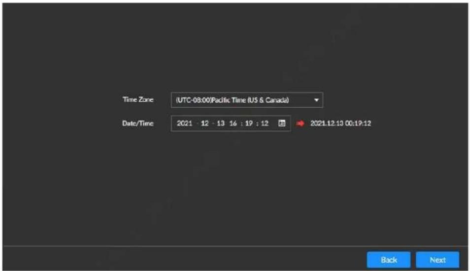
Step 3 Select the Time Zone and Date/Time, and then click Next.
Figure 8-2 Device initialization

Step 4 Set the admin login password and configure the parameters.
Table 8-1 Descriptions of password setting parameters
| Parameter Description | |
| User | The default username is admin. |
| Password Confirm password | The password should consist of 8 to 32 non-blank characters and contain at least two types of characters among upper case, lower case, number, and special characters (excluding "", "", :, "", &"). Please set a high-security password according to the password strength prompt.   |
| Prompt question |  login interface. The system displays the prompt question you have set to help you recall the password. login interface. The system displays the prompt question you have set to help you recall the password. |
Step 5 Click Next.
Figure 8-3 Password protection

Step 6 Set password protection. See more details in Table 8-2.
After setting password protection, you can reset the admin login password by using reserved email or security question if the password is lost. Reset password, see more details in 9.6.3.4 Resetting Admin Password.

Click to disable the setup of the Reserved Email and Security Questions if you do not want to set password protection.
Table 8-2 Password Protection Description
| Password Protection Method | Description |
| Reserved Email | Set reserved email. To reset the admin login password, you need to scan the QR code, then type the security code the reserved email received.After the setup, you can modify the reserved email on the Attribute interface.See more details in 9.6.3.2 Modifying User. |
| Security questions | Set the security questions and answers. Provide correct answers to the security questions and you can reset the admin password. |
Step 7 Click Finish.

Click Enter Quick Settings to set the basic information of the Device. For more details, see 8.1.2 Quick Configuration.
Figure 8-4 Initialization completion interface
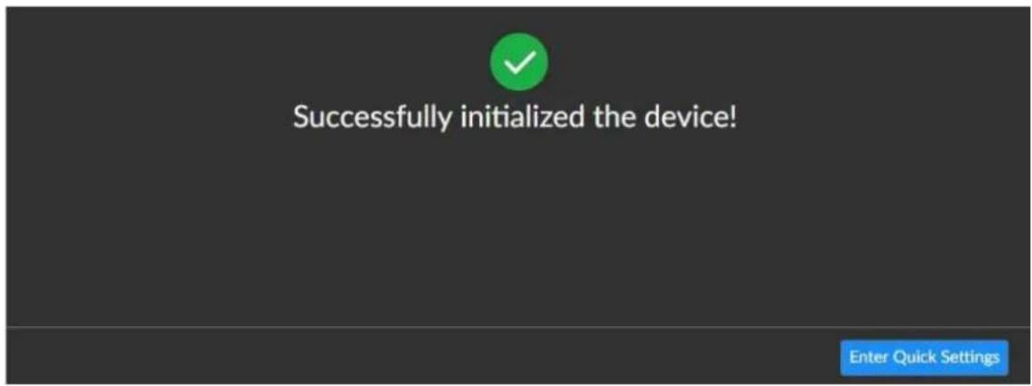
8.1.2 Quick Configuration
After the Device is initialized, you can quickly set the IP address on Quick Configuration interface. Step 1 On the Successfully initialized the device interface, click Enter Quick Settings
Figure 8-5IP setting

Step 2 Set IP address

Only 1 Ethernet Port of the equipment. Before setting IP address, confirm the ethernet port has already connected to the Internet.
1) Click the icon 📋 corresponding to the network port.
2) For more details ab out parameters, see Table 8-3.
Table 8-3 Descriptions of NIC editing
| Parameter Description | |
| Speed | Maximum network transmission speed of current NIC. |
| Use dynamic IP address | When there is a DHCP server on the network, select the check box to use dynamic IP address. System can distribute a dynamic IP address to the Device.There is no need to set IP address manually. |
| Use static IP address | Set static IP address, subnet mask and gateway. It is to set a static IP address for the Device. |
| MTU | Set NIC MTU value. The default setup is 1500 Byte.We recommend that you check the MTU value of the gateway first and then set the device MTU value equal to or smaller than the gateway value. It is to reduce the packets slightly and enhance network transmission efficiency.[GS76]Changing MTU value might result in NIC reboot, network offline and affect current running operation. Be careful. |
3) Click OK.
The system returns to the IP Set interface.
Step 3 Set DNS Server parameters.
You can select to obtain the DNS server address automatically or manually enter.

When activating the domain name service, this step must not be skipped.
- Obtain DNS server address automatically: Select Obtain DNS server address automatically, and then the system automatically gets the IP address of the DNS server.
- Use the following DNS server address: Select Use the following DNS server address, and then you need to enter the IP address of the preferred DNS and the alternate DNS.
Step 4 Set the default NIC
Select Default Ethernet from the Default NIC drop-down list as needed.

Only NIC which has been connected to the network can be used as the Default NIC.
Step 5 Click Finish.
8.2 Login and Logout
This section introduces how to log in and log out in the case of one or two display monitors:
- Logging in to Local Interface: For first-time login or switching to a new user account, login in on one monitor, and then the other monitor logs in simultaneously. The settings interface can only be entered on monitor1.
- Log out: Log out on one monitor and the other monitor logs out simultaneously.
8.2.1 Logging in to Local Interface

By default, live view is only allowed after login in. If Live View Control is enabled in System Settings > System Settings, the Live View interface can be displayed without login in.
This manual takes the live view after default login in as the example.
Step 1 Power on the Device.
Figure 8-6 Local login
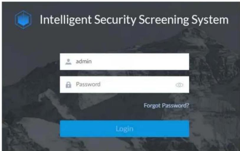
Step 2 Enter the username and password.

- The default username is admin and the password is the login password set during device initialization. To keep the Device safe, we recommend you to modify the admin password regularly and properly keep new passwords.
- If the login password of the admin account is lost, click Forgot Password? And then reset the admin password. For details, see 9.6.3.4 Resetting Admin Password.
Step 3 Click Login.
Figure 8-7 Local security screening interface

8.2.2 Logging in to Web Interface
You can use Google Chrome, Firefox, or other browsers to log in to the web interface, and then you can set up and operate the Device, and maintain the system.

- When using a general browser to log in to the web interface, you can only set up the Device, but cannot play live view. We recommend you to play the live view of the real-time security screening video through the local interface.
• We recommend you to operate in the local interface.
Step 1 Open the browser, enter the IP address of the Device, and press Enter.
Figure 8-8 WEB logging in interface
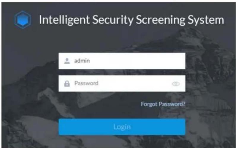
Step 2 Enter the username and password.

- The default username is admin and the password is the login password set during device initialization. To keep the Device safe, we recommend you to modify the admin password regularly and properly keep new passwords.
- If the login password of the admin account is lost, click Forgot Password? And then reset the admin password. For details, see 9.6.3.4 Resetting Admin Password.
Step 3 Click Login.
8.2.3 Logging out
At the lower-left corner of the live view interface admin, select the username in the login status, select Log Out, and then the system returns to the login interface.
8.3 Baggage Statistics
8.3.1 Baggage Search
Search and count all scanned baggage, and view relevant videos.
Procedures
Step 1 Click on the homepage.
Figure 8-9 Homepage

Step 2 Select BAGGAGE MANAGEMENT > BAGGAGE SEARCH.
Figure 8-10 Baggage Search
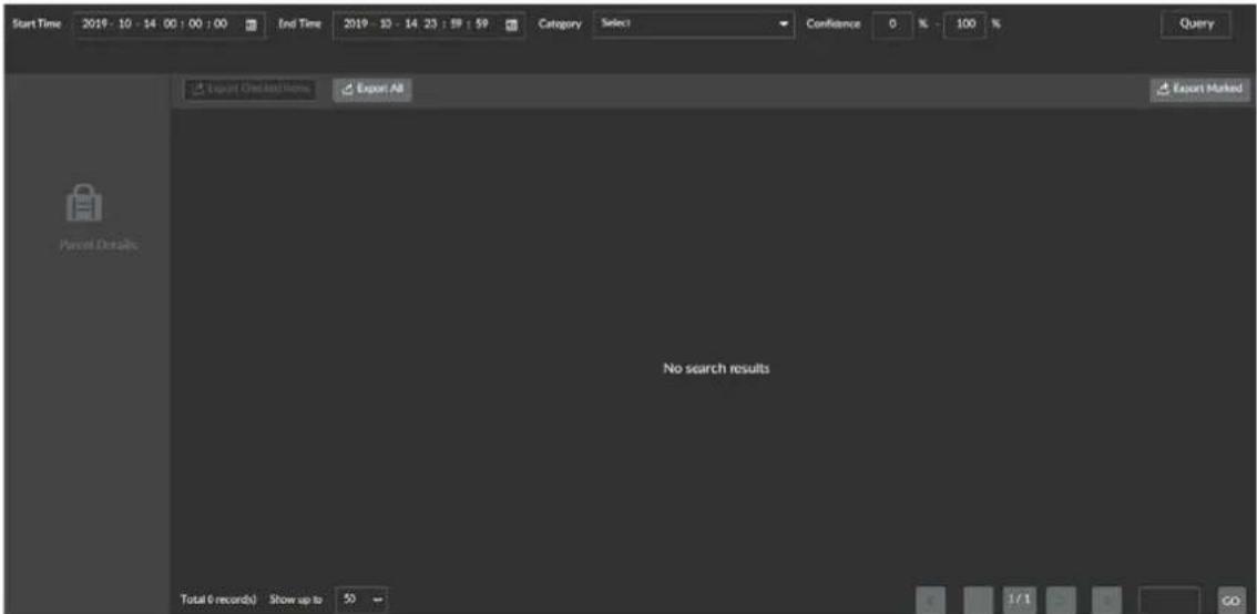
Step 3 Set the query period, select the Category, enter Confidence, and then click Query.

- The End Time must be later than the Start Time. The longest period for query is 30 days.
- The default category is all. Query is possible only after selecting a specific category. Types of item include guns, explosives, knives, lighter, spray cans, liquid, electronic products, umbrellas, brass knuckles, handcuffs, nightsticks and uncategorized items.
Figure 8-11 Baggage search results


• Dual-view security screening machine: 2 channels display
- Single-view security screening machine: only single picture display
Step 4 View recordings: Select queried pictures and click ▶ on the left to play the recordings linked with the baggage 10s before and after the baggage passes the screening machine.

Prerequisite: The associated recording channel has been configured. For more details, see 8.3.5 Security Screening.
Step 5 View details: Click a queried picture and the system displays the baggage details.
Figure 8-12 Baggage details

- Export Checked Items: Select the baggage information to be exported, and click Export Checked Items to export selected information; enter the password of the current account on the pop-up window to export checked items to local.
- Export All: Click Export All to export all information of queried baggage; enter the password of the current account on the pop-up window to export checked items to local.

- If entering the wrong password 5 times continuously, the device will jump to the login interface.
- Only user groups configured with the File Backup permission can export package files. For how to configure user group permissions, see 9.6.3.1 Adding User.
8.3.2 Report Search
Support baggage data statistics and displaying data in the form of line chart or report.
Procedures
Step 1 Select BAGGAGE MANAGEMENT > REPORT SEARCH.
Figure 8-13 Report search

Step 2 Set the query period, select the category of item, and then click Query.
Figure 8-14 Line chart

Step 3 Click Data and the system displays data in the form of report.
Figure 8-15 Report
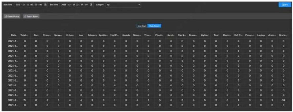
Related Operations
Export data:
- Click Export Picture to export the line chart.
- Click Export Report to export data reports.
8.3.3 Voice Broadcast
Configure the port, voice file, and broadcast rules for voice broadcast. The settings come into effect immediately.
8.3.3.1 Uploading Voice File
Step 1 Select BAGGAGE MANAGEMENT > VOICE BROADCAST.
Figure 8-16 Voice broadcast
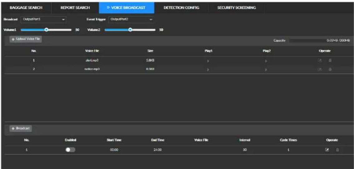
Step 2 Click Upload Voice File and then select voice files to upload.
Uploaded voice files are displayed in the list. Click file.

to make an audition of this voice

- Voice files are in MP3 format only. A single voice file shall not exceed 32 MB. Up to 50 voice files can be uploaded, provided that the total size does not exceed 200 M.
● The Capacity at upper-right corner shows the total capacity of uploaded voice files. - A voice file cannot be deleted if a test voice file is being played.
8.3.3.2 Configuring Voice Broadcast
You can use different voice files to be broadcast in different periods.
Voice Broadcast Rules
Table 8-4 Voice Broadcast Rules
| Use of Audio Ports Audio | Broadcast Rules |
| Broadcast and alarm use different audio ports | Follow the queue strategy when multiple broadcasts (or alarms) are in queue.When the previous voice broadcast (or alarm) is still on, the next broadcast (or alarm) should be waiting in queue.When the previous voice broadcast (or alarm) is played and several broadcasts (or alarms) are in queue, the newest is played and the others are not.If several alarm broadcast voices are waiting simultaneously, the one with highest danger level is played. |
| Broadcast and alarm share the same audio port | ● The alarm has higher priority than the broadcast at the same playing period.◇ When the current broadcast is being played and an alarm comes in, the broadcast stops. After the alarm ends, the broadcast does not resume playing, but waits until the next play interval comes.◇ When an alarm is being played and a broadcast comes in, the alarm continues, and the broadcast is not played.● When broadcasts and alarms are in queue, use the queue strategy.◇ When a broadcast is being played and another comes in, the latter waits in queue.◇ When an alarm is being played and another comes in, the latter waits in queue. |
| Audition file is activated when broadcast or alarm is playing | If you activate audition file when a broadcast or alarm is being played, the audition file prevails. After the audition file, the interrupted broadcast or alarm does not resume playing.Priority of play: Audition file > Alarm > Broadcast. |
Procedures
Step 1 Select BAGGAGE MANAGEMENT > VOICE BROADCAST.
Figure 8-17 Voice broadcast

Step 2 Set the output ports corresponding to broadcast and alarm events.
Step 3 Set the volume.
Volume 1 corresponds to Output Port 1. Volume 2 corresponds to Output Port 2.
Step 4 Click Broadcast.
Figure 8-18 Voice broadcast

Step 5 Set the voice broadcast parameters. For more details, see Table 8-5.

The periods between two voice broadcasts cannot be overlaid.
Table 8-5 Set voice broadcast parameters
| Parameter Description | |
| Enabled Enables the voice | broadcast. |
| Start time, End time | Set the broadcast period in 24-hour format. |
| Voice file Select uploaded | voice files. |
| Interval | In the preset period, the interval between repeated playback of the corresponding voice file is in seconds.The range is from 5 s to 600 s. |
| Cycle times | The number of times for repeatedly playing a voice file in each period.The upper limit is 5. |
Step 6 Click OK.
Related Operations
- Edit: Click 📋 corresponding to the voice broadcast and you can edit this broadcast.
- Delete: Click 📋 corresponding to the voice broadcast and you can delete this broadcast.
8.3.4 Configuring Detection Parameters
Configure the detection of multiple suspect items, and set the linkage alarm when the device detects the corresponding item.
Step 1 Select BAGGAGE MANAGEMENT > DETECTION CONFIG > analysis.
Figure 8-19AI Analysis
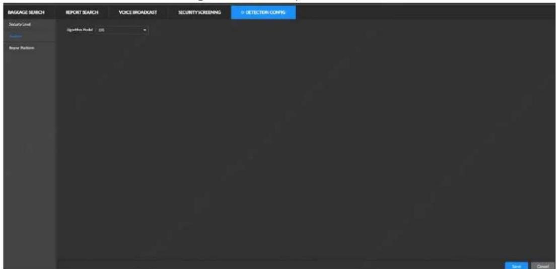
Step 2 For more details about AI Analysis, see Table 8-6.
Table 8-6 AI Analysis Parameters Description
| Parameter Description | |
| Sensitivity | The higher the sensitivity, the easier the suspect items are detected. |
| Smart Plan Select a smart plan as required. | |
Step 3 Click Save.
8.3.5 Configuring Suspect Item
Default suspect items vary according to different algorithm models. You can modify the suspect item as needed.
Step 1 Select BAGGAGE MANAGEMENT > DETECTION CONFIG > suspect item.
Figure 8-20 Suspect Item

Step 2 Enable the item detection as needed.

means enabled;

disabled.
Step 3 In the list, click 📋 corresponding to the suspect items.
Figure 8-21 Modification
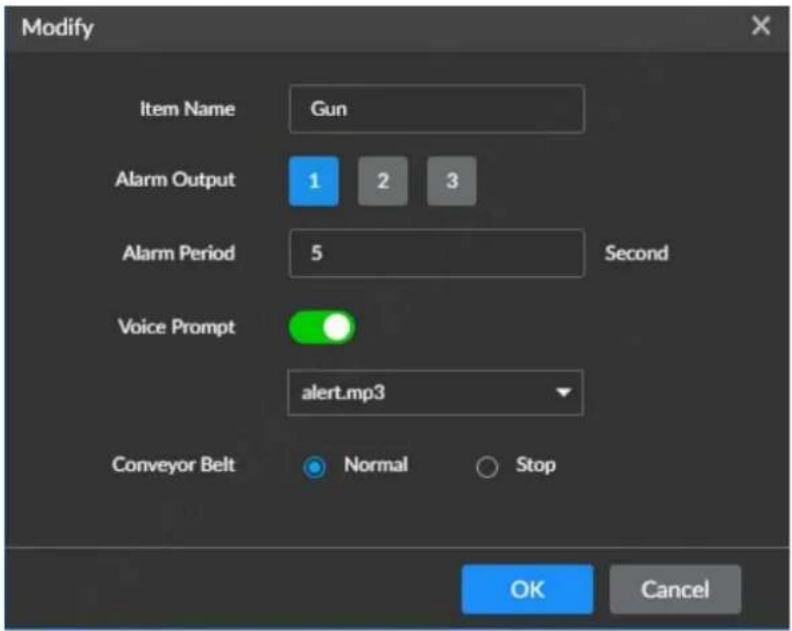
Step 4 Set the parameters of suspect items. For more details, see Table 8-7.
Table 8-7 Descriptions of suspect item parameters
| Parameter Description | |
| Enabled | The Device starts detecting these items when they are enabled. |
| Danger level The danger level of suspect items. | |
| Alarm output | Connect an external alarm device (such as an alarm light or siren) to the alarm output port. Select the checkbox, set the alarm output device, and activate the alarm action output port. When an alarm event takes place, the system can associate with corresponding alarm output devices. |
| Alarm Delay | After the alarm event ends, the alarm will be extended for a period of time to stop.The range is from 0 s to 300 s. |
| Voice prompt | Enable voice prompt, and select the corresponding voice file in the drop-down list of File Name. When an alarm event takes place, the system plays selected voice file.Make sure the corresponding voice file is added. For how to upload voice files, see 8.3.1Baggage Search.If multiple voice alarms are triggered simultaneously, the previously triggered voice broadcast must finish playing before the next starts playing. After the previous voice broadcast is played, if several broadcasts are in queue, only play the newest. |
| Conveyor | Set the working mode of linkage conveyor after configuring the detection of such suspect items, normal linkage mode and stop mode are available. |
| Report to platform | When this function is enabled, information of suspect items is reported to associated platforms.Before using this function, make sure the Device is already added to the platform. |
| Similarity | When the confidence level of the scanned items is equal to or greater than the preset value, the system reports this alarm information to the platform. |
Step 5 Click OK.
8.3.6 Security Screening
Select the camera channel of the baggage entrance and baggage exit based on the specific installation of cameras.

The camera at the baggage entrance is pointed at the baggage entrance of the equipment to monitor the flow of people and baggage; the camera at the baggage exit is pointed at the baggage exit of the equipment to monitor the flow of people and baggage. When inquiring about packages, people-package linkage function can be used to effectively retrieve person who carry the package.
Step 1 Select BAGGAGE MANAGEMENT > SECURITY SCREENING.
Figure 8-22 Security screening

Step 2 Set security screening parameters. For more details, see Table 8-8.
Table 8-8 Description of security screening parameters
| Parameter Description | |
| Power Saving Mode | Select to enable the power saving mode. When the mode is enabled, if no new packages are placed on the conveyor within 15s, the conveyor will automatically stop until packages are placed on it again. |
| High Density Alert | After selection, when thick impenetrable objects are detected, the objects in the image are displayed in red. |
| Vertical Flip | After selection, the live view of packages is vertically flipped to help recognize objects of different shapes. |
| Max Zoom Times | Set the max zoom times of the detection image, which is 8x by default and up to 64x is supported. |
| Scan Direction | Set the scan direction of the Device. You can select dual-direction, forward scan or reverse scan.Dual direction: The scanned object enters the tunnel from the package entrance/exit port of the Device, and the package will be displayed in pictures.Forward scan: When the scanned object enters the tunnel from the baggage entrance of the Device, it will trigger the Xray to scan the package. When it enters the tunnel from the baggage exit, it will not trigger the X-ray.Reverse scan: When the scanned object enters the tunnel from the bag exit of the Device, it will trigger the X-ray to scan package. When it enters the tunnel from the bag entrance, it will not trigger the X-ray. The baggage entrance is the tunnel entrance away from the nameplate label. The baggage entrance is the tunnel entrance away from the nameplate label. |
| Camera for bag entrance | Set the cameras corresponding to the bag entrance and bag exit.Click to review the live videos of corresponding camera channels. |
| Camera for baggage exit |
Step 3 Click Setting.
Figure 8-23 Package Statistics

Table 8-9 Description of package statistics parameters
| Parameter Description | |
| Setting Status Bar | Select to display accumulated number of packages or number of temporary packages. |
| Restoring the number of temporary package when logging in | After enabled, the counter will be reset after logging in to the Device again. |
Step 4 (Optional) Click Counter Reset to clear the number of temporary packages.
Step 5 Click OK to save the package statistics parameters.
Step 6 Click Save.
8.4 Video Playback
You can search and play back recordings or pictures stored in the Device, and export recordings or pictures to a specified location.
8.4.1 Playback
Search and play back recordings by camera, recording type, and recording time.
Step 1
Click

on the homepage.
Step 2
Select PLAYBACK.
The system displays Video Playback interface, see Figure 8-24.
Figure 8-24 Playback (1)

Step 3 Select camera on the left, and click the Record below.
Step 4 Select the recording type and stream type.
Types of recording include all record, manual record, video detection, and IO alarm.
• All record: Search all recordings.
• Manual record: Search manual recordings by the user.
• Video detection: Search linked video detection recordings.
• IO alarm: Search linked local alarm recordings.
• Query time is set by the following methods:
- Method A: Click the date or time in the time frame to modify date or time value.
- Method B: Click the date or time in the time frame, rotate the mouse wheel to adjust date or time values.
- Method C: Click 📋, set date and time on the displayed calendar, and then click OK.

On the calendar interface, if a date is underlined by dots (such as ), meaning this date has recordings.
Figure 8-25 Calendar interface
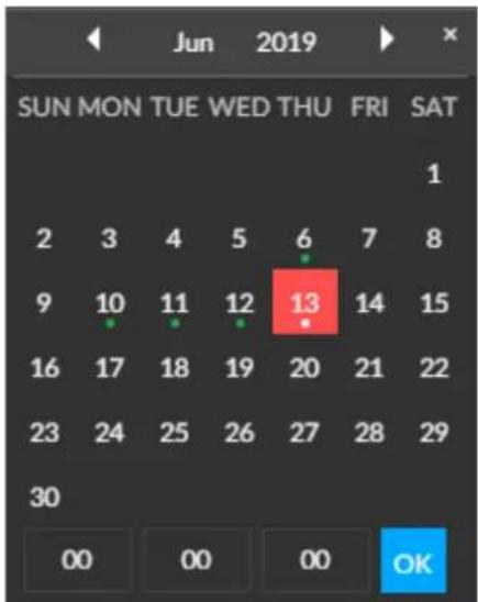
Step 5 Click Search.
The system displays the query results. The thumbnails of recordings are displayed at the top of the interface, and the periods of recordings are displayed on the time bar (green means recordings exist).

- The list at the left side displays the selected cameras. Click a camera and the corresponding thumbnail of recordings is displayed at the right side.
- Click or to display the hidden thumbnails.
- Point to the thumbnail to view information of the corresponding recording including the name of the camera storing this file, start time and end time of the recording.
Figure 8-26 Recording query results

Step 6 Drag the thumbnail to the play window, or double-click the thumbnail.
The system starts playing back the recording. For more details about the description of playback icons, see Table 8-10.

The number of playback windows depends on the number of dragged or selected thumbnails. Up to 16 windows can be selected. The system automatically adjusts the size of each playback window based on the original scale of played-back recordings.
Table 8-10 Description of playback control icons
| Icon Description | |
 | Click the icon to switch to operation synchronization mode. Then you can control multiple recordings simultaneously, such as fast play and stop at the same time.Click to stop operation synchronization. |
| [SDHW] | When multiple recordings are played back at the same time, clicking this icon to the time sync mode, and all windows play recordings at the same time point as that of the currently selected window.Click to stop time synchronization. Click Click  and the system enables operation synchronization at the sametime. and the system enables operation synchronization at the sametime. ... only way to cancel operation synchronization is to click . ... only way to cancel operation synchronization is to click . |
 | Click this icon to play back recordings slowly.Slow playback can reduce the speed to × 1/2 , × 1/4 , × 1/8 , and × 1/16 of the normal speed.Click this icon once to reduce the playback speed by one level. |
| [BYGZ] | Click this icon if you want to switch to frame-by-frame reverse playback. This function enables only when playback pauses. This function enables only when playback pauses. |
| [3WDZ] | Click this icon to reverse playback, at this time the icon turns to . Click[ C280 ][C3K0 ]to stop reverse play. |
 | Click this icon and the recording starts playback, and the icon turns to . [60TK]Click to stop. |
| [0CDH] | Click this icon if you want to switch to frame-by-frame playback.This function enables only when playback pauses. |
[4TAO] | Click this icon to play back recordings quickly.Fast playback can accelerate the speed of play to × 1 , × 2 , × 4 , × 8 , × 16 times the normal speed. Click this icon once to increase the playback speed by one level.Shows the playback speed. Drag left or right and the recording is played in the fast reverse or fast forward mode. |
| [DD04] | Click this icon to take snapshots. |
| [XGZY] | Click this icon to clip the recording, and save the clipped recording to a specified location. For details, see 8.4.2Clipping Recording. |
 | Control the volume.[6628]Drag to adjust the volume.Clickto switch to the mute mode, and the icon turns to. Clickto unmute. |
| K | Click this icon to display the window in full screen. |
Time bar | Display the type of recording and the period of recording.The time bar shows two recording bars. The upper one displays the recording time of the selected window, and the lower one displays the recording time of all selected cameras.On the time bar, recording types vary from colors. A blank time bar means there are no recordings. Time cursor displays the date and time of recording playback. The time cursor automatically adjusts according to the playback progress.The following operations can be done on the time bar:Click the time bar, rotate the mouse wheel, and adjust the time accuracy of the time bar.Press and hold the time bar, drag it left or right to check the hidden recording time.Drag the time cursor to adjust the start time of the recording playback.Click or drag the time cursor to a position on the time bar where there is a recording. The system starts playing back the recording from the located time point.Click or drag the time cursor to a position where no recordings exist to stop recording playback.Right-click menu. Right-click the playback window and the system displays the right-click menu.Digital: Partially zoom in the recording image and view the details of this part.Original: Set the image scale of the playing window.Enable: The system automatically adjusts the image scale of the playing window based on the video resolution.Disable: The system automatically adjusts the size of the playing window based on the number of selected cameras and the blank of the play region.Audio: Set audio output. Time cursor displays the date and time of recording playback. The time cursor automatically adjusts according to the playback progress.The following operations can be done on the time bar:Click the time bar, rotate the mouse wheel, and adjust the time accuracy of the time bar.Press and hold the time bar, drag it left or right to check the hidden recording time.Drag the time cursor to adjust the start time of the recording playback.Click or drag the time cursor to a position on the time bar where there is a recording. The system starts playing back the recording from the located time point.Click or drag the time cursor to a position where no recordings exist to stop recording playback.Right-click menu. Right-click the playback window and the system displays the right-click menu.Digital: Partially zoom in the recording image and view the details of this part.Original: Set the image scale of the playing window.Enable: The system automatically adjusts the image scale of the playing window based on the video resolution.Disable: The system automatically adjusts the size of the playing window based on the number of selected cameras and the blank of the play region.Audio: Set audio output. |
 | Point to the playback window and the system displays the task bar. Click this icon to close the recording playback window. |
8.4.2 Clipping Recording
Clip the recording, and save the clipped recording to a specified location.

When you operate on local interface, connect the USB storage device to the Device.
Step 1 Select PLAYBACK.
The playback interface is displayed.
Step 2 Play back the recording. For details, see 8.4.1Playback.
Step 3 Click . [↓]
The time bar displays recording clip frame, see Figure 8-27.
Figure 8-27 Recording clip frame

Step 4 Hold the recording clip frame (such as the blue frame in Figure 8-27), drag it left or right to select the start time and end time for clipping.
Step 5 Click Save immediately.
The system displays Save interface.
Step 6 Click Browse to choose where to save the clipped recording.
Step 7 Click OK.
Save the clipped recording to where you choose.
8.4.3 Image Playback
You can view manual snapshot and video detection snapshot.
Step 1 Select PLAYBACK.
The Playback interface is displayed.
Step 2 Select the camera, and then click the Image.
The image playback interface is displayed. See Figure 8-28.

Only one camera can be selected.
Figure 8-28 Image playback (1)

Step 3 Select the type of image, including manual snapshot and video detection snapshot.
Step 4 Query time is set by the following methods:
• Method A: Click the date or time in the time frame to modify date or time value.
- Method B: Click the date or time in the time frame, rotate the mouse wheel to adjust date or time values.
- Method C: Click 📄, set date and time on the displayed calendar, and then click OK, see Figure 8-29 Calendar interface.

On the calendar interface, if a date is underlined by dots (such as ), meaning this date has images.
Figure 8-29 Calendar interface

Step 5 Click Search.
The system displays queried image thumbnails.

- The list at the left side displays the selected cameras. Click a camera and the corresponding thumbnail of recordings is displayed at the right side.
- Click or to display the hidden thumbnails.
- Point to the thumbnail to view information of the corresponding recording including the name of the camera storing this file, start time and end time of the recording.
- Point to the list of thumbnail and the interface displays ↗. Click this icon to hide the thumbnail list. After hiding the list of thumbnails, click ↘ to display the thumbnail list.
Step 6 Drag the thumbnail to the play window, or double-click the thumbnail.
The system starts image playback as shown in Figure 8-30. For details, see Table 8-11.
Figure 8-30 Image Playback
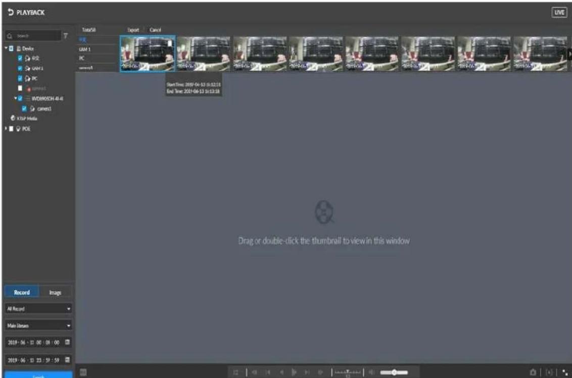

Point to the playing window, and the following icons are displayed.
Table 8-11 Description of Image playback icons
| Icon Description | |
 | Click this icon to switch to the previous or next image. |
 | Switch images.When playing back images one by one, click this icon to switch to the previous or next image.When playing back multiple images simultaneously, click this icon to switch to the previous or next group of images.Click this icon to display the window in full screen. Click again to exit full screen. |
8.4.4 Exporting Files
Export recordings or images to a specified location to prevent their loss.

- By default, the system exports recordings in the format of DAV, and images in JPG.
- When you operate on local interface, connect the USB storage device to the Device.
Step 1 Select PLAYBACK.
The Playback interface is displayed.
Step 2 Search recordings or images.
1) Select a camera.
2) Click the Record or Image on the bottom on the interface.
3) Set the search conditions.
4) Click Search.
The system displays the thumbnails of searched recordings or images.
Step 3 Select the thumbnails of recordings or images you want to export.
- Point to the thumbnail and click □ to select the thumbnail. √ means the thumbnail is selected.
- Click Select Again and the thumbnails of all recordings or images are canceled.
Step 4 Click.


In this chapter we take exporting a recording as an example, and the actual interface shall prevail.
The system displays Save interface. See Figure 8-31.
Figure 8-31 Click Save.

Step 5 Click Browse to choose where to save the clipped recording.
Step 6 Click OK.
9 Settings
9.1 Device Management
You can manage the Device or a connected camera.
9.1.1 Managing the Device
You can view and modify the information of the Device and storage plans.
9.1.1.1 Device Attributes
You can view the information of the Device such as MAC address, video input and output, and modify Device name and descriptions.
Step 1 Click on the homepage, and select Device.
Step 2 Select the root node from the device list, and then click ATTRIBUTE. The system displays Attribute interface. See Figure 9-1.
Figure 9-1 Attribute

Step 3 Modify the Name and Description, and click Save.
9.1.1.2 Storage Configuration
Set the global recording storage plan and image storage plan based on your needs.

By default, recording and image storage plans set on this interface applies to all added cameras. You can select a remote device to set the corresponding storage plan. For details, see 9.1.2.4.5 Storage Configuration.
Step 1 Select DEVICE.
Step 2 Select the root node from the device list, and then click STORAGE. The system displays STORAGE interface. See Figure 9-2.
Figure 9-2 Storage

Step 3 For more details about parameters, see Table 9-1.
Table 9-1 Description of storage parameters
| Parameter Description | ||
| Recording | Storage | Select the recording plan.Continuous recording: Camera records 24 hours.No recording: Camera does not record.Event recording: Camera records only when an event alarm is triggered. |
| Manual record | Settings Set the length of a manual recording.On the live view interface, if you click to start recording and do not click the icon again to end recording, the system automatically ends the recording based on the Manual Record you set. | |
| Pre-record | This parameter is set only when selecting Event Recording.The range is from 10 s to 30 s. | |
| Image | Manual snapshot | Set the number of images and speed of taking snapshots. |
| Event snapshot | Set the interval for taking snapshots when an alarm-triggering event takes place.Select Self-defining to customize the interval for taking snapshots.The longest interval is 3600s. | |
Step 4 Click Save.
9.1.2 Managing Camera
You can connect cameras to the Device, modifying the IP address and configurations of cameras, and exporting the information of cameras, and more.
9.1.2.1 Initializing Camera
Set the initial login password and IP address of a camera by initializing it. Only an initialized camera can be connected to the Device.
Step 1
Click on the live view interface.
The system displays Homepage interface, see Figure 9-3.
Figure 9-3 Homepage

Step 2 Select DEVICE.
The system displays Device interface. See Figure 9-4.
Figure 9-4 Device management

Step 3 Click Add.
The system displays Smart Add interface.
Step 4 Click Start Search.
The system starts searching for cameras and displays the research results. See Figure 9-5.
Figure 9-5 Cameras

Step 5 Select an uninitialized camera and click Initialize.
The system displays Initialize interface. See Figure 9-6.

By clicking Initialization State and then select Uninitialized, you can quickly screen out uninitialized cameras.
Figure 9-6 Device initialization

Step 6 Set the password and password protection method for the camera.

By enabling Using current device password and password protection, the camera automatically uses Device's admin account information (login password and email). There is no need to set password and email. You can go to Step 7.
1) Click if you want to cancel Using current device password and password protection.
The system displays Password Setting interface. See Figure 9-7.
Figure 9-7 Setting Password

Table 9-2 Descriptions of password setting parameters
| Parameter Description | |
| Username | The default username is admin. |
| Password | Set and confirm the password.The password should consist of 8 to 32 non-blank characters and contain at least two types of characters among upper case, lower case, number, and special characters (excluding "", "", "", "", &). Please set a high-security password according to the password strength prompt. |
| Confirm password | |
2) Click Next.
The system displays Password Protection interface. See Figure 9-8.
Figure 9-8 Password protection

3) Set email.
After setting the email, if you forget the password of the remote device, you can retrieve the password through the email.
Step 7 Click Next.
The system displays Modification IP interface. See Figure 9-9.
Figure 9-9 Modifying IP

Step 8 Set camera IP address.
- If there is a DHCP server in the network, after selecting DHCP, the camera will automatically obtain a dynamic IP address without entering the IP address, subnet mask, and default gateway.
- If you select Static, you need to input IP address, subnet mask, default gateway.

- When modifying multiple cameras at the same time, you need to set the Incremental Value. The fourth digit of the IP Address is increased in turn according to the incremental value you set.
- If there is IP conflict when modifying static IP address, device pops up IP conflict prompt. If IP addresses are modified in bulk, device automatically skips the conflicted IP and begins the IP allocation according to the incremental value.
Step 9 Click Next.
The system starts initializing camera and displays the initialization results.
Step 10 Click Confirm and add or click OK.
- Click Confirm and add to complete the initialization and add the camera. The system then returns to the Add Device interface.
- Click OK to complete the initialization. The system then returns to the Add Device interface.
9.1.2.2 Adding Camera
The system supports Smart Add, Manual Add, and Import CVS File. For details, see Table 9-3.
Table 9-3 Methods of adding devices
| Adding methods | Description |
| Smart add | Search for cameras in the same network to filter and add. For details, see 9.1.2.2.2Smart Add.When you are not sure about the IP address of the camera, useSmart Add. |
| Manual add | Manually enter the IP address, username, and password of a camera to add the Device. See 9.1.2.2.3Manual add.When adding a few cameras and their IP address, username, and password are known, useManual Add. |
| Import CVS file | Fill information of the camera into a template and add the device by importing the template. For details, see 9.1.2.2.4Import CVS file.When adding cameras in bulk and their IP addresses, usernames, and passwords are different, useImport CVS File. |
9.1.2.2.1 Smart Add
Step 1 Select DEVICE.
The system displays device management interface.
Step 2 Click Add.
The system displays Smart Add interface. See Figure 9-10.
Figure 9-10Smart Add

Step 3 Click Start Search.
The system starts searching for cameras in the same network segment and displays the research results. See Figure 9-11.
Figure 9-11 Search results

Click LIVE and the system displays the live view of the camera. See Figure 9-12.

The live view image of a camera can be reviewed only when the camera's user (admin) password is admin or the same as the user (admin) password of the Device.
Figure 9-12 Live view
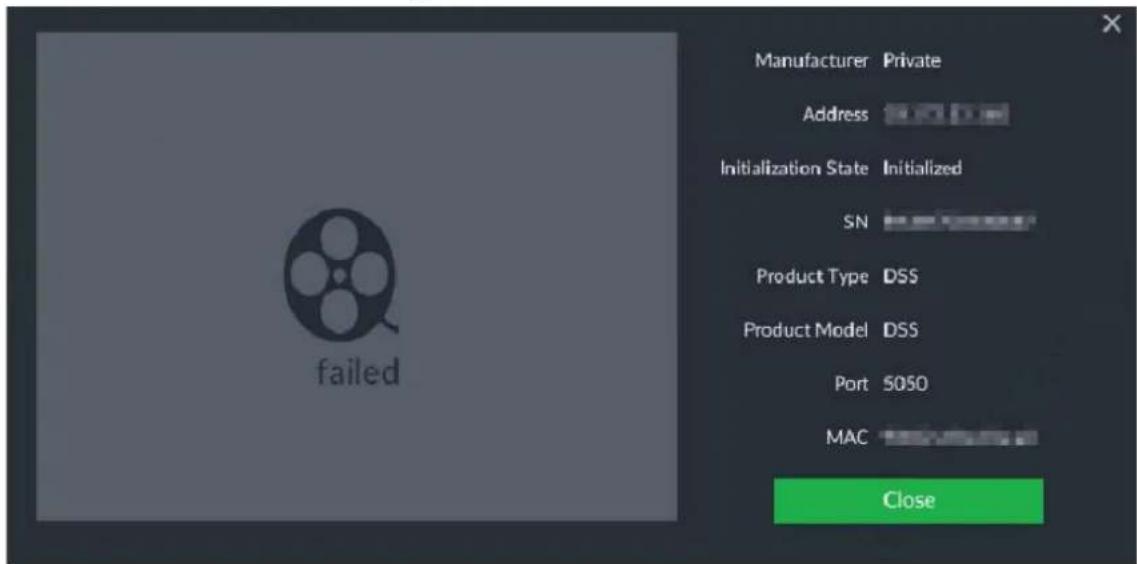
Step 4 Adding a camera
- Add a single-channel camera.
Select a camera, and then click Add. The system starts adding the selected device and displays Add onfirm interface. See Figure 9-13.

When adding a camera click Cancel and the camera is not added; click Stop to stop add this camera.
Double-click the address, username, password, manufacturer, and port of the camera to modify the corresponding information.
When you failed to add a camera, modify the information of the device according to onscreen instructions. Click Try again and you can add the camera again.
Figure 9-13 Add confirm (1)
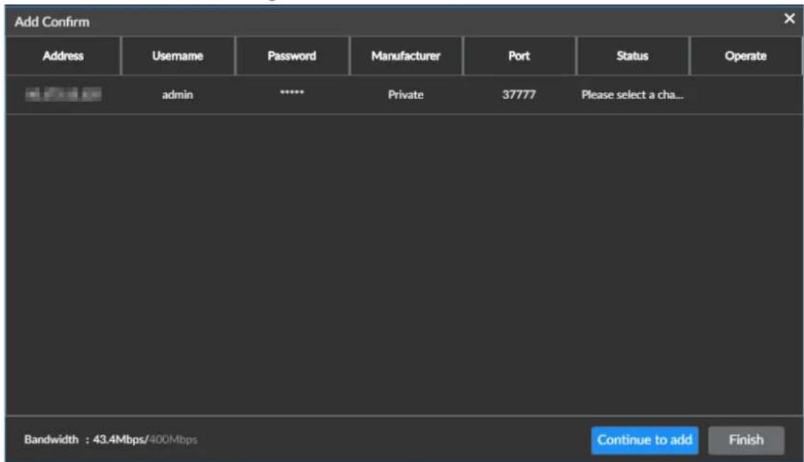
- Add a multi-channel camera.
-
After selecting a camera, click Add.
The system displays add confirm interface. -
Double-click Please select a channel.
The system displays Video device interface. See Figure 9-14.
Figure 9-14 Video device
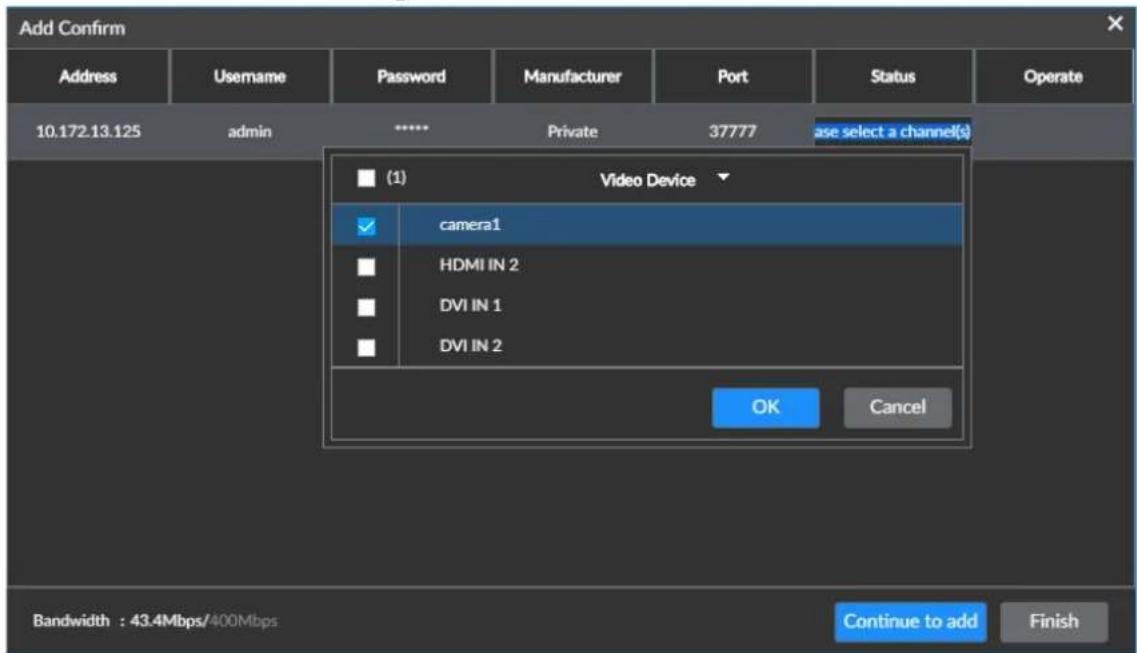
- Select the channel you want to add.
Click and enter keywords into the search bar to quickly locate the channel you want to add.
- Click OK to add the selected channel.
Step 5 Click Continue to add or Finish.
- Click Continue to add and then the system adds the current camera. The Add Device interface is displayed, where you can add another camera.
- Click Finish to complete adding. The Device interface is displayed, where you can view the information of added camera.
9.1.2.2.2 Manual add
Step 1 Select DEVICE.
The system displays Device management interface
Step 2 Select Add > Manual Add.
The system displays Manual Add interface. See Figure 9-15.
Figure 9-15 Manual add(1)

Step 3 Click Manual Add.
The system displays the information of camera you need to fill in. See Figure 9-16.
Figure 9-16 Manual add(2)

Step 4 For more details about parameters, see Table 9-4.
Table 9-4 Parameter descriptions
| Parameter Description | |
| Device type | Select the type of the camera. The default type is Devices. |
| Manufacturer | Select the communication protocol of the camera. The default is Private.Double-click Private and you can select another protocol.When adding a stream media device, select Rtsp as the communication protocol, and enter the RTSP address of the device into the Address item. |
| Address | Enter the IP address or RTSP address of the camera.[IMAGE]For instance, the RTSP format of the Onvif device is rtsp://:@/cam/realmonitor?channel=1&subtype=0 , For example rtsp://admin:admin@192.168.20.25:554/cam/realmonitor? channel =1&subtype=0。● Port: 554 by default● Channel: The channel number of the stream media device you need to add.● Subtype: Stream type: 0 means main stream; 1 means sub stream. |
| Username | Enter the username and password of the camera.[IMAGE]When adding a stream media device, no need to set the Username, Password, and Port. |
| Password | |
| Port | Enter the port number of the camera. |
| Operation | Delete or Add new rows.● Click [icon] to delete the camera information. After selecting multiple lines of remote device information, click Delete to delete the camera information in bulk.● Click + to add a new row. After entering the camera information, you can add multiple cameras at the same time. |
Step 5 Adding a camera
- Add a single-channel camera.
Select a camera, and then click Add. The system starts adding the selected device. The Add Confirm interface is displayed. See Figure 9-17.

When adding a camera click Cancel and the camera is not added; click Stop to stop add this camera.
Double-click the address, username, password, manufacturer, and port of the camera to modify the corresponding information.
When you failed to add a camera, modify the information of the device according to onscreen instructions. Click Try again and you can add the camera again.
Figure 9-17 Add confirm(1)
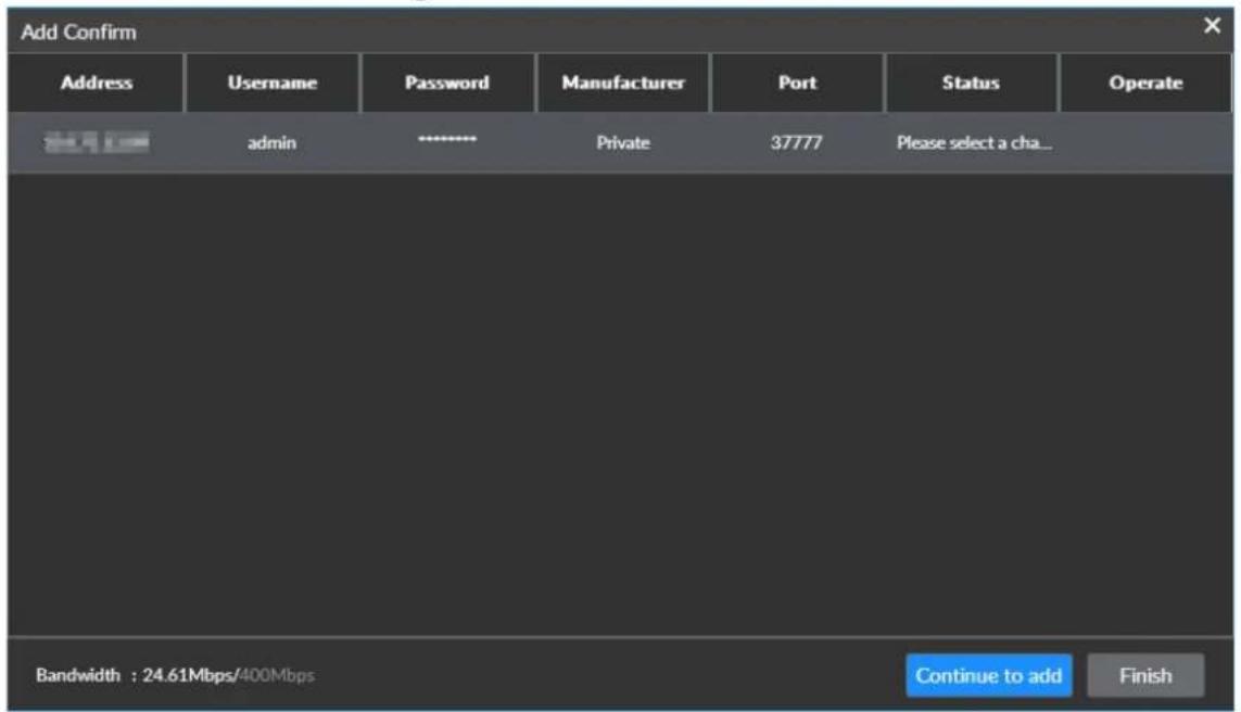
- Add a multi-channel camera
- After selecting a camera, click Add.
The system displays Add Confirm interface. See Figure 9-18.
Figure 9-18 Add confirm(2)

- Double-click Please select a channel.
- Select the channel you want to add.
Click ▼ and enter keywords into the search bar to quickly locate the channel you want to add.
- Click OK to add the selected channel.
Step 6 Click Continue to add or Finish.
- Click Continue to add and then the system adds the current camera. The Add Device interface is displayed, where you can add another camera.
- Click Finish to complete adding. The Device interface is displayed, where you can view the information of added camera.
9.1.2.2.3 Import CVS file
Step 1 Select DEVICE.
The system displays Device management interface
Step 2 Select Add > Import CSV File.
The system displays Import CSV File interface. See Figure 9-19.
Figure 9-19 Import CSV file

Step 3 Fill in the template.
1) Click Download Template to download template.
Saving path might vary according to interfaces you operate on, and the actual interface shall prevail.
- On local interface, you can select where to save files.

In local operations, connect the USB storage device to the Device.
- On web interface, files are stored in the default path set up in the browser.
2) Fill in the template according to the real fact and click Save.
The system displays the information of camera you need to fill in. See Figure 9-20.

If the camera information is not complete, import the template, and then complete the information.
Figure 9-20 Template
| A | B | C | D | E | F | G |
| IP Address | Port | Port No. | Channel Name | Manufacturer | Username | Password |
Step 4 Import the template.
1) Click Browse and select the template.
2) Click Import.
The system displays the information of the imported information of the camera.

- When the camera information is incomplete, complete the information.
- Click 📋 if you want to delete this camera.
Step 5 Adding a camera
- Add a single-channel camera.
Select a camera, and then click Add. The system starts adding the selected device and displays Add Confirm interface. See Figure 9-21.

When adding a camera click Cancel and the camera is not added; click Stop to stop add this camera.
Double-click the address, username, password, manufacturer, and port of the camera to modify the corresponding information.
When you failed to add a camera, modify the information of the device according to onscreen instructions. Click Try again and you can add the camera again.
Figure 9-21 Add confirm(1)
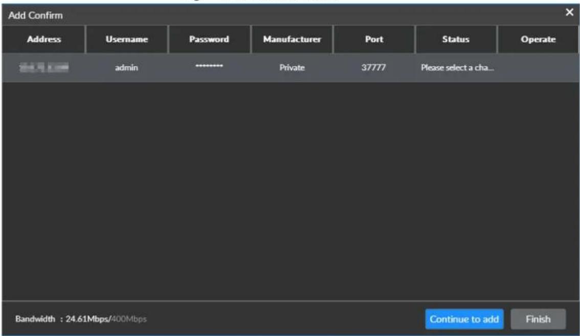
- Add a multi-channel camera
- After selecting a camera, click Add.
The system displays add confirm interface. See Figure 9-22.
Figure 9-22 Add confirm (2)

- Double-click Please select a channel.
- Select the channel you want to add.
Click ▼ and enter keywords into the search bar to quickly locate the channel you want to add.
- Click OK to add the selected channel.
Step 6 Click Continue to add or Finish.
- Click Continue to add and then the system adds the current camera. The Add Device interface is displayed, where you can add another camera.
- Click Finish to complete adding. The Device interface is displayed, where you can view the information of added camera.
9.1.2.3 Modifying IP Address of Camera
You can modify the IP addresses of cameras that are not added.

- You can only modify the IP address of an already initialized camera. For details, see 9.1.2.1 Initializing Camera.
- You can only modify the IP address of a camera connected by a private protocol.
- For how to modify the IP address of an added camera. See 9.1.2.4.2 Setting Connections.
Step 1 Click on the homepage, and select Device.
The system displays Device Management interface.
Step 2 Click Add and select the Smart Add.
The system displays Smart Add interface.
Step 3 Click Start Search.
The system starts searching for cameras and displays the research results. See Figure 9-23.

You can click ↗ to filter the search according to the settings of manufacture, IP address.
Figure 9-23 Cameras
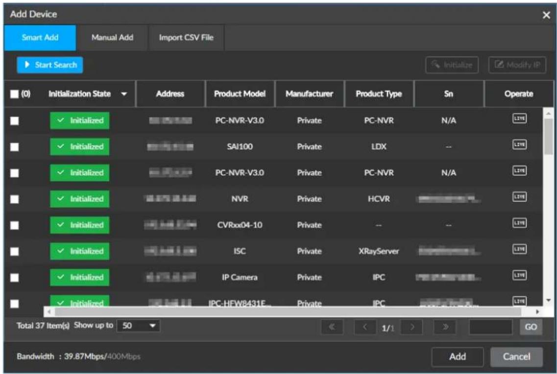
Step 4 Select the camera, and click Modify IP.
The system displays Modify IP interface. See Figure 9-24.

Modifying IP addresses of multiple devices in bulk is allowed. But in doing so, make sure that the username and password of all cameras are the same.
Figure 9-24 Modifying IP Address of Camera (1)

Step 5 Set camera IP address.
- If you select DHCP, there is no need to input IP address, subnet mask, and default gateway. Device automatically allocates the IP address to the camera.
- If you select Static, you need to input IP address, subnet mask, default gateway.

- When modifying multiple cameras at the same time, you need to set the Incremental Value. The fourth digit of the IP Address is increased in turn according to the incremental value you set.
- If there is IP conflict when modifying static IP address, device pops up IP conflict prompt. If IP addresses are modified in bulk, device automatically skips the conflicted IP and begins the IP allocation according to the incremental value.
Step 6 Enter the username and password of the camera.
Step 7 Click Next.
The IP modification result is displayed.
Step 8 Click OK.
9.1.2.4 Configuring Camera
You can set the information such as attribute, connection, and video parameters of added cameras.

The functions and interfaces might vary according to different cameras you add, and the actual interface shall prevail.
9.1.2.4.1 Attribute Settings
You can set the camera name and view device information.
Step 1 Select DEVICE.
Step 2 Select a camera and click the ATTRIBUTE.
The system displays Attribute interface. See Figure 9-25.
Figure 9-25 Attribute

Step 3 For more details about parameters, see Table 9-5.
Table 9-5 Descriptions of attribute parameter
| Parameter | Description |
| Name | Set the name of the camera.Enable Sync to camera, and then save settings, the modified name will be synchronized to the camera. |
| Description | Enter descriptions of this camera. |
| Device information | Displays information of the camera including its model, serial number, MAC address, storage capacities of audio and video files, amount of alarm inputs and outputs, and system version. |
Step 4 Click Save.
9.1.2.4.2 Setting Connections
You can modify the connection parameters of the camera such as IP address and port number.
Step 1 Select DEVICE.
The system displays Device Management interface.
Step 2 Select a camera and click CONNECTION.
The system displays Connection interface. See Figure 9-26.
Figure 9-26 Connection

Step 3 Modifying IP Address.
1) Click the icon 📋 corresponding to the Address. The system displays Modification IP interface. See Figure 9-27.
Figure 9-27 Modifying IP

2) Enter IP address, subnet mask, and gateway.
3) Click OK to save the modifications.
Step 4 Modify the port number.

The port number corresponds to the connection protocol of the device. The protocols vary from different port numbers.
1) Click the icon 📋 corresponding to the Port. The system displays Modify Port interface. See Figure 9-28.
Figure 9-28 Modify the port.

2) Modify the port number.
3) Click OK.
Step 5 For more details about parameters, see Table 9-6.
Table 9-6 Descriptions of connection parameter
| Parameter Description | |
| Manufacturer | Select the communication protocol of the camera. |
| Username Enter | the username and password of the camera. |
| Password | The password should consist of 8 to 32 non-blank characters and contain at least two types of characters among upper case, lower case, number, and special characters (excluding "", "", "", "", &). Please set a high-security password according to the password strength prompt. |
| Link type | Displays the link type between the Device and camera. The default setting is Self-adaptive. |
| Cache strategy | Set the caching strategy of video streams of camera.● Self-adaptive: The system auto adjusts the video stream cache based on the bandwidth.● Real-time: Guarantees that videos are real-time, but small bandwidth can result in lagged videos.● Smooth: Ensures that videos are smooth, but sometimes at the cost of low definition. |
Step 6 Click Save.
9.1.2.4.3 Setting Video Parameters
Set video parameters of different stream types based on the actual bandwidth. The functions and interfaces might vary from different front-end equipment, and the actual interface shall prevail.
Step 1 Select DEVICE.
The system displays device management interface.
Step 2 After selecting a camera, click VIDEO.
The system displays Video interface. See Figure 9-29.
Figure 9-29 Video

Step 3 Click Main Stream, Sub Stream 1 or Sub Stream 2.

Different devices work with different stream modes and the actual interface shall prevail.
Table 9-7 Descriptions of video parameters
| Parameter | Description |
| Smart code | Enabling smart code helps improve image compression performance and reduce storage space.[605W]Enable smart code and the Device will not support the third stream, ROI, and other functions. The actual interface shall prevail |
| Encode mode | Used to set the video encode mode.MJPEG: Motion JPEG encoding.H.264: Main Profile encodingH.264H: High Profile encodingH.264B: Baseline Profile encoding |
| Resolution | Set video resolution. The higher the resolution, the better the image quality.[4460]Different devices support different resolutions and the actual interface shall prevail. |
| FPS | Set frames per second. The higher the FPS, the more real and more smooth the image is. |
| Stream mode | Set thevideo stream mode.CBR (Constant Bit Rate): The bit rate changes little and keeps close to the defined bit rate value.VBR (Variable Bit Rate): The bit rate changes along with environment. |
| Quality | Set the video image quality, including low, meddle, and high.When the Stream Mode is set to VBR, this parameter can be set. |
| Stream | Set the video stream value.Main stream: Setting of the stream value changes the image quality; the higher the value, the better the image quality.Sub Stream: In the CBR stream mode, the bit rate changes little and keeps close to the defined bit rate value; in the VBR stream mode, The bit rate changes along with environment and the maximum value keeps close to the defined bit rate value. |
| I frame interval | Used to define the amount of P frames between two I frames. It is recommended to set the I frame interval two times as the FPS. |
Step 4 Set Event Video Quality, and set FPS and Stream Mode.

Only the main stream mode allows for setting Event Video Quality.
Step 5 Click Save.
9.1.2.4.4 Setting OSD
Overlay information such as time and channel on video image of camera.
Step 1 Select DEVICE.
The system displays device management interface.
Step 2 Select a camera and click OSD.
The system displays OSD interface. See Figure 9-30
Figure 9-30 OSD

Step 3 Set the stack information based on actual needs.
- Device Name
◇ Click to overlay the name onto the video.
◇ Click ☑ if you want to modify the device name and where it is displayed.
- Time Stack
◇ Click to overlay the time onto the video.
◇ Click ☑ if you want to modify the device name and where it is displayed.
- Geographical Position
- When setting the position, click 📞 or 📊 to create a textbox, and then enter the position information of the camera.
Figure 9-31 Geographical Position

◇ Click to adjust the alignment of texts.
◇ Click ☐ or ☐ again to create a textbox over or under the previously created textbox.
◇ Click 🔒 to delete the textbox.
-
Drag the textbox to a proper position.
-
Click.
Step 4 Click Save.
9.1.2.4.5 Storage Configuration
Set the recording storage plan and image storage plan of cameras as needed.
Step 1 Select DEVICE.
The system displays device management interface.
Step 2 Select a camera and click STORAGE.
The system displays STORAGE interface. See Figure 9-32.
Figure 9-32 Storage

Step 3 Select Inherit local storage plan or Customize.
- Inherit local storage plan: The camera inherits the global storage plan of the Device.
- Customize: Customizes the storage plan of camera.
Step 4 For more details about parameters, see Table 9-8.

When selecting Inherit local storage plan, only Record Stream needs to be set up.
Table 9-8 Description of storage parameters
| Parameter Description | ||
| Recording | Recording plan. | Select the recording plan.Continuous recording: Camera records 24 hours.No recording: Camera does not record.Event recording: Camera records only when an event alarm is triggered. |
| Manual record | Settings Set the length of a manual recording.On the live view interface, if you click  to start recording and do not click the icon again to end recording, the system automatically ends the recording based on the Manual Record you set. to start recording and do not click the icon again to end recording, the system automatically ends the recording based on the Manual Record you set. | |
| Record stream | Select Record Stream mode, including main stream, sub stream1 and sub stream2. | |
| Image | Manual snapshot | Set the number of images and speed of taking snapshots. |
| Event snapshot | Set the interval for taking snapshots when an alarm-triggering event takes place.SelectSelf-definingto customize the interval for taking snapshots. The longest interval is 3600s. | |
Step 5 Click Save.
9.1.2.5 Exporting Camera Information
You can export the information of added cameras. In the case of information loss caused by restoration of factory settings or system errors, import camera information to quickly restore camera.
Step 1 Select DEVICE.
The system displays Device Management interface.
Step 2 Click at the lower-left corner.
The system displays Export interface. See Figure 9-33.

Click Download Template to download template of the camera, and then you can add cameras by using the template.
Figure 9-33 Export

Step 3 Select Whether The Encryption.
- If selecting Yes, the system exports encrypted backup files which can only be viewed in the Device.
- If selecting No, the system exports csv files which can be opened by using Excel and other tools. An exported csv file includes the IP address, port number, channel number, channel name, manufacturer, and username (without password) of the camera.

When exporting non-encrypted files, properly save them to avoid data leakage.
Step 4 Click OK.
The system displays the prompt interface.
Step 5 Click Save File.
Saving path might vary according to interfaces you operate on, and the actual interface shall prevail.
- On local interface, you can select where to save files.

In local operations, connect the USB storage device to the Device.
- On web interface, files are stored in the default path set up in the browser.
9.1.2.6 Viewing Device Connection Status
Go to the Device interface, and view the connection status of cameras in the device list.
Such camera_AXIS status means the device is online, and ISC means the device is offline.
- Right-click an offline device and select Connect if you want to connect to this device again.
- Right-click an online device and select Disconnect if you want to disconnect with this device.
9.1.2.7 Deleting Camera
Go to the Device interface, where you can delete an added camera or delete them in bulk.
- Single delete
◇ Select a camera and click .
◇ In the device list, right-click a camera, select Delete.
- Delete in bulk
Click , and then the check box is displayed in the device list. Select multiple cameras and click .
In the device list, select a camera, hold Ctrl or Shift. Then you can select cameras you want to delete, and then click .
9.2 Network Management
Set the network parameters of the Device and make sure that this Device is interconnected with other devices.
9.2.1 Modifying IP Address
Modify the IP address and DNS server of the Device based on network planning.
Step 1 Click on the homepage, select NETWORK > TCP/IPv4. The system displays TCP/IPv4 interface. See Figure 9-34.

To select the items to be displayed, you can click
Figure 9-34 TCP/IPv4

Step 2 Click the icon 📋 corresponding to the network port.
The system displays Edit Ethernet network interface. See Figure 9-35.
Figure 9-35 Edit Ethernet network
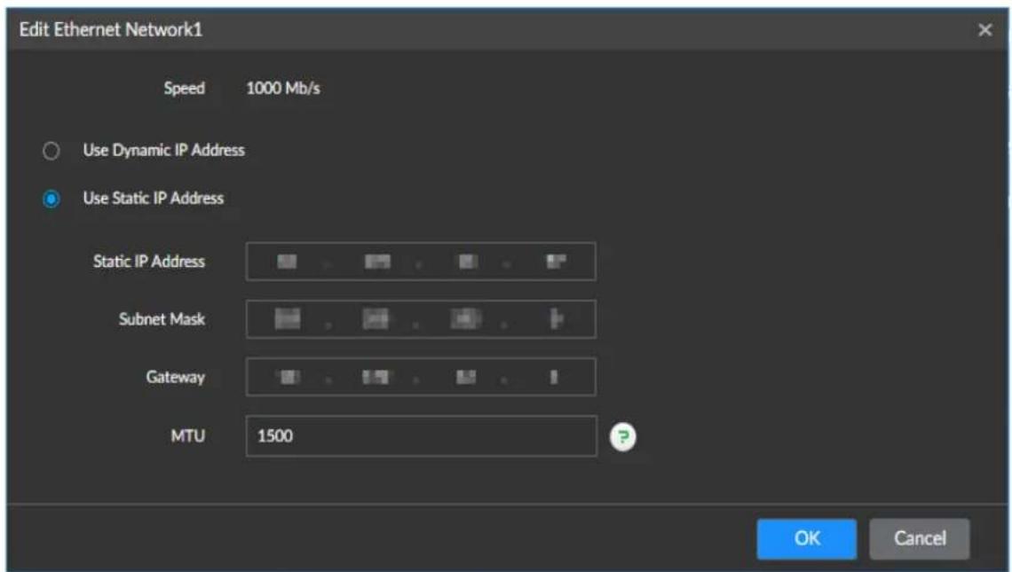
Step 3 For more details about parameters, see Table 9-9.
Table 9-9 Descriptions of NIC editing
| Parameter Description | |
| Speed | Maximum network transmission speed of current NIC. |
| Parameter Description | |
| Use dynamic IP address | When there is a DH CP server on the network, select the check box to use dynamic IP address. System can distribute a dynamic IP address to the Device. There is no need to manually set IP address and more. |
| Use static IP address | Set static IP address, subnet mask and gateway. It is to set a static IP address for the Device. |
| MTU | Set NIC MTU value. The default setup is 1500 Byte.We recommend that you check the MTU value of the gateway first and then set the device MTU value equal to or smaller than the gateway value. It is to reduce the packets slightly and enhance network transmission efficiency. Changing MTU value might result in NIC reboot, network offline and affect current running operation. Be careful. Changing MTU value might result in NIC reboot, network offline and affect current running operation. Be careful. |
Step 4 Click OK.
The system returns to the TCP/IPv4 interface.
Step 5 Set DNS Server parameters.
You can select to obtain the DNS server address automatically or manually enter.

When activating the domain name service, this step must not be skipped.
- Obtain DNS server address automatically: Select Obtain DNS server address automatically, and then the system automatically gets the IP address of the DNS server.
- Use the following DNS server address: Select Use the following DNS server address, and then you need to enter the IP address of the preferred DNS and the alternate DNS.
Step 6 Set the default NIC
Select Default Ethernet from the Default NIC drop-down list as needed.

Only NIC which has been connected to the network can be used as the Default NIC.
Step 7 Click Save.
9.2.2 Setting Port Number
You can set device port number.
Step 1 Select NETWORK > PORT.
The system displays Port interface. See Figure 9-36.
Figure 9-36 Port

Step 2 For more details about parameters, see Table 9-10.
Table 9-10 Descriptions of port parameters
| Parameter Description | |
| Max connection | Select the number of connections from 1 to 128 as needed. |
| TCP port | Select the number of connections from 1025 to 65535 as needed. The default value is 37777. |
| RTSP port | Select the number of connections from 1 to 65535 as needed. The default value is 554. |
| HTTP port | Select the number of connections from 1 to 65535 as needed. The default value is 80.If the value you set is not 80, add the port number after the IP address when you use browser to log in to the Device. |
| HTTPS port | Select the number of connections from 1 to 65535 as needed. The default value is 443. |
| UDP port | Select the number of connections from 1025 to 65535 as needed. The default value is 37778. |
Step 3 Click Save.
9.2.3 Configuring Email
Configure email information, and enable email alarm linkage. When the Device has alarm events, the system automatically sends email to the user.
Step 1 Select NETWORK > EMAIL.
The system displays Email interface. See Figure 9-37.
Figure 9-37 Email

Step 2
Click

to enable the email function.
Table 9-11 Descriptions of email parameter
| Parameter Description | |
| Email server | Select email server type, including Customize, 126Email, 163Email, and QQEmail. |
| Server address | Enter the email server address. For details, see Table 9-12. |
| Encryption | Select the encryption type of the email server from NONE, SSL, and TLS. For details, see Table 9-12. |
| Port | Enter the port number of the email server. For details, see Table 9-12. |
| Username and password | Enter the username and password of the email server. For details, see Table 9-12. |
Table 9-12 Description of common email configuration parameters
| Email Type | Email server | Encryption | Port | Description |
| smtp.qq.com | SSL | 465 | The encryption method cannot select NONE.Email must subscribe SMTP service.The password must use the Authorization Code, and the QQ password and email password are invalid.Authorization code is obtained when the SMTP service is enabled in the mailbox. | |
| 163 smtp.1 | 63.com | SSL | 465/994 | ● Email must subscribe SMTP service.● The password must use the Authorization Password, and the email password is invalid.[WHOX]Authorization password is obtained when the SMTP service is enabled in the mailbox. |
| TLS 25 | ||||
| NONE 25 | ||||
| 126 | smtp.126.com | NONE | 25 | Email must subscribe SMTP service. |
Step 3 Add the information of email receiver
1) Click Add.
2) Enter the email address of the receiver, see Figure 9-38.
Figure 9-38 Email address

◇ Click Add or + to add other receivers' email addresses.
◇ Click ☐ to delete an added receiver.
Select a receiver. The Delete button is displayed. Click Delete to delete the selected receiver.
Step 4 Click Save.
Step 5 (Optional) Test whether the emails can be sent and received as intended.
1) In Test Mail, select or enter a receiver's email address.
2) Click Send.
When the configuration is correct, the system pops up a message of success, and the receiver will receive the test mail.
Otherwise, the system pops up a message of failure, and the receiver will not receive the test mail.
9.2.4 Setting SWITCH
Set the SWITCH. When IPC is directly connected to the PoE port of the Device, the system auto distributes an IP address to the IPC based on the preset IP segment. The Device auto connects to this IPC.

- Do not connect a SWITCH to the PoE; otherwise the connection might fail.
- The Device enables SWITCH by default, and the IP segment is 10.1.1.1. Maintaining the default setting is recommended.
Procedures
Step 1 Select NETWORK > PORT.
The system displays SWITCH interface. See Figure 9-39.
Figure 9-39 SWITCH
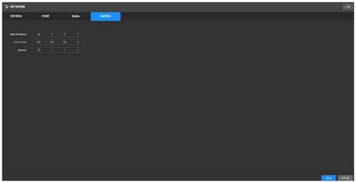
Step 2 Set IP address

The IP address of the SWITCH cannot be in the same segment as the IP address of the Device. Using the default IP is recommended.
Step 3 Click Save.
9.2.5 Configuring Auto Register
Step 1 Select NETWORK > PORT.
The system displays Auto Register interface, see Figure 9-40.
Figure 9-40 Auto Register

Step 2 Click to auto enable auto register.
Step 3 Set relevant parameters of auto register.
Step 4 Click Save.
9.2.6 Configuring UPnP
Step 1 Select NETWORK > PORT.
The system displays UPnP interface. See Figure 9-41.
Figure 9-41 UPnP

Step 2
Click

to

to enable port mapping.
Step 3 Set the Intranet IP and Internet IP.
Step 4 Set the port mapping table.
- Click 2 in the function bar, and then select function types displayed in the port mapping table, including service name, protocol, internal port, external port, and operation, and more.
Figure 9-42 Port mapping table (1)
| Service Name | Protocol | Internal Port | External Port | Operate |
| HTTP | TCP | 80 | 8000 | 7 |
- Click 📋 corresponding to the mapping port to modify port mapping (only the external port number can be modified), and then click OK.
Figure 9-43 Port mapping table (2)

Figure 9-44 Port mapping modification

Step 5 Click Save.
9.3 Storage Management
Storage management includes managing the stored resources (such as recordings) and storage space, so you can use and improve utilization ratio of storage space.
9.3.1 HDD
The physical HDD refers to the HDD installed on the Device. On this interface you can view information such as the capacity (free space, total space) of the disk, and disk information.
Click on the homepage, and then select STORAGE > HDD. The HDD interface is displayed. See Figure 9-45.
There is a corresponding icon near the HDD name after you create the RAID and hotspare HDD.
- RAID HDD.
Global hotspare HDD.
- Invalid private hotspare HDD.
Figure 9-45 HDD

9.3.1.2 View S.M.A.R.T Information
S.M.A.R.T is so called Self-Monitoring Analysis and Reporting Technology. It is a standard used to detect HDD drive status and report potential issues. The system monitors and records the running status of HDDs and compare parameters with preset safety range. When the monitored parameters fall out of the safety range, the system prompts alarms to guarantee the safety of HDD data.

You can view the S.M.A.R.T information of only one HDD at one time.
On the HDD interface, select a HDD, and click S.M.A.R.T. The S.M.A.R.T interface is displayed.
See Figure 9-46. Check whether the HDD is normal. If any anomaly is found, timely repair the HDD.
Figure 9-46 View S.M.A.R.T Information

other
S.M.A.R.T | Sn | Note | Value | Worst | Boundary | Original Data | State | |---|---|---|---|---|---|---| | 1 | Read Error Rate | 81 | 64 | 44 | 124936950 | Better | | 3 | Spin Up Time | 94 | 94 | 0 | 0 | Better | | 4 | Start/Stop Co... | 100 | 100 | 20 | 42 | Better | | 5 | Reallocated S... | 100 | 100 | 10 | 0 | Better | | 7 | Seek Error Rate | 83 | 60 | 45 | 217988076 | Better | | 9 | Power On Ho... | 99 | 99 | 0 | 942 | Better | | 10 | Spin-up Retry ... | 100 | 100 | 97 | 0 | Better | | 12 | Power On/O... | 100 | 100 | 20 | 42 | Better | | 184 | End-to-End Fr... | 100 | 100 | 99 | 0 | Better | Close9.3.1.3 Set Storage Strategy
You can set the recording strategy when the HDD space is full.
Step 1 Select STORAGE > HDD.
The system displays HDD interface.
Step 2 Click Storage Strategy.
The system displays Set Storage Strategy interface. See Figure 9-47.
Figure 9-47 Set Storage Strategy
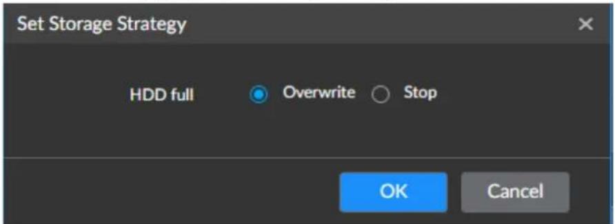
Step 3 Set Storage Strategy.
- Overwrite: If the free space of HDD is below 50 GB or is less than 1% of the total space (the system select the larger), the system continues recording and overwrites the recording file stored the earliest.
- Stop: If the free space of HDD is below 50 GB or is less than 1% of the total space (the system select the larger), the system stops recording.
Step 4 Click OK.
9.3.1.4 HDD Defragmentation
After the HDD works for a period time, since it is repeatedly written or files are deleted, the files are saved on the discontinued physical position on the HDD. It might result in too much HDD fragmentation and slow down the HDD access speed. The HDD optimization is to organize the fragmentation files on the HDD and make the fragmentation files become the continuous files. It can enhance HDD whole performance and running speed.

HDD optimization can result in the loss of some recordings. Be careful.
Step 1 Select STORAGE > HDD.
Step 2 Select one or several HDD(s) and click HDD Optimization
The system displays Set Defragmentation Strategy interface. See Figure 9-48.
Figure 9-48 Set the HDD defragmentation strategy.
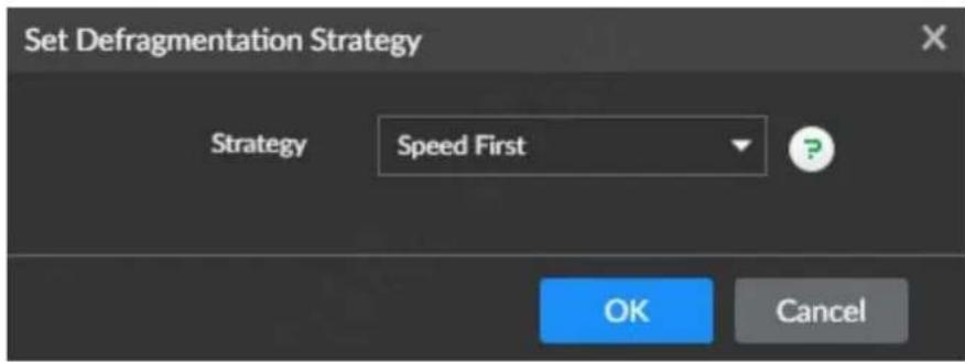
Step 3 Select the HDD defragmentation strategy..
• Speed first: HDD optimization at a high speed up to 100 M/s.
- Business first: The system auto adjusts the HDD optimization speed based on the business load on the Device.
Step 4 Click OK.
The system displays the prompt interface.
Step 5 Click OK.
The system starts HDD optimization, and the disk State shows HDD Optimizing. After optimization, the State goes back to Running.
9.3.1.5 Formatting

Formatting clears all files from the disk. Be careful.
Go to the HDD interface, select one or several HDD(s), and click Format to format the selected HDD.
9.3.2 RAID Management
RAID (Redundant Array of Independent Disks) is a data storage virtualization technology that combines multiple physical HDD components into a single logical unit for the purposes of data redundancy, performance improvement, or both.

- Types of RAID supported by the Device include RAID 0, RAID 1, RAID 5, RAID 6, and RAID 10. More details, see Appendix 3.
- Use enterprise-class HDDs when creating RAID, and surveillance-class HDDs in the single HDD mode.
9.3.2.1 Creating RAID
RAID has different levels (RAID 0, RAID 1, RAID 5). Every level has its own data protection, data availability, and performance level. You can create RAID based on your own needs.

- Creating RAID will result in clearing all existing data in the disk. Be careful.
- When the Device is installed with a maximum number of HDDs, the system follows the "5+5+1+1" strategy. When creating RAID 5 in one button. 5 means the disk amount in RAID 5, and 1 means 1 global hotspare.
Step 1 Select STORAGE>RAID>RAID.
The system displays RAID interface. See Figure 9-49.
Figure 9-49 RAID(1)

Step 2 Click Add.
The system displays Creating RAID interface. See Figure 9-50.
Figure 9-50 Creating RAID(1)

Step 3 Setting RAID Parameters.
Select how to create RAID based on your own needs. Options include Manual and Auto.
- Manual: The system creates a specified RAID type according to the selected HDD amount.
- Select Manual.
- Select HDD for creating RAID.
- For more details about parameters, see Table 9-13.
Table 9-13 Parameters descriptions of creating RAID
| Parameter Description | |
| Storage device | Select the storage device for the HDD and the HDD to be added to RAID.The different RAID types need different HDD amounts, the actual situation shall prevail. |
| RAID | Select the type of RAID you want to create. |
| Working mode | Select the resource allocation mode for RAID. The self-adaptive is the default setting.In the self-adaptive mode, the system automatically adjusts the RAID synchronization speed according to the current business load. When no external business exist, the synchronization speed is high. When there is external business, the synchronization speed is low. |
| Name Name the RAID. | |
- One-click RAID: The system creates RAID 5 according to the amount of HDD. The system displays RAID interface. See Figure 9-51.
Figure 9-51 Creating RAID (2)

Step 4 Click Next.
The system displays Confirm Info interface.
Step 5 Confirm the information.

If the input information is wrong, click Back to set RAID parameters again.
Step 6 Click Create.
The system starts creating RAID. After creation, the RAID information is displayed in the list.
- Click ▶ to the right of the RAID name to unfold the RAID HDD list. You can view the capacity and status of each member disk.
- Click ⓘ and the Details interface is displayed, where you can view RAID details.
9.3.2.2 HDD Defragmentation
Go to the RAID interface, select one or more RAIDs, and click HDD Optimization to defragment the fragments and disorderly files in the disk. See 9.3.1.4HDD Defragmentation.
9.3.2.3 Deleting RAID

RAID deletion will result in clearing all files in the RAID and disbands the RAID. Be careful.
Go to the RAID interface, select one or more RAIDs, and click Delete to delete the selected RAID(s).
9.3.2.4 Formatting RAID

Formatting the RAID will result in clearing all files. Be careful.
Go to the RAID interface, select one or more RAIDs, and click Format to format the selected RAID(s).
9.3.2.5 Creating Hotspare HDD
When a HDD of the RAID group is malfunctioning or has errors, the hotspare HDD takes over the malfunctioning HDD to prevent data loss and guarantee the reliability of the storage system.
Step 1 Select STORAGE > RAID > Hotspare.
The system displays Hotspare interface. See Figure 9-52.
Figure 9-52 Hotspare

Step 2 Click Add.
The system displays Add Hotspare interface. See Figure 9-53.
Figure 9-53 Adding hotspare

Step 3 Select the Creation Type of the hotspare HDD.
- Global hotspare: Create hotspare for all RAID, not a hotspare HDD for a specified RAID group.
- Private hotspare: Select Private Hotspare and Add it to a RAID group. The private hotspare HDD is for a specified RAID group.
Step 4 Select one or several HDD(s) and then click Next.
The system displays Confirm Info interface.
Step 5 Confirm the information.

Click Back to select hotspare HDD(s) again if you want to change settings. For details, see Step 3.
Step 6 Click Create to save the settings.
The system displays information of added hotspare HDD.
9.4 Event
Set the alarm manner for system errors. The alarm is triggered if errors happen during the operation of the Device.

Different devices support different event types, and the actual interface shall prevail.
Step 1 Click on the homepage, and select EVENT.
The system displays Event interface. See Figure 9-54.
Figure 9-54 Event


• √ means the abnormal event alarm is enabled.
• This chapter takes setting No-HDD as an example.
Step 2 Select the specific device (or root directory) from the device list.
Step 3 Select the specific event alarm. For example, No-HDD.
The system displays No-HDD interface. See Figure 9-55.
Figure 9-55 No-HDD
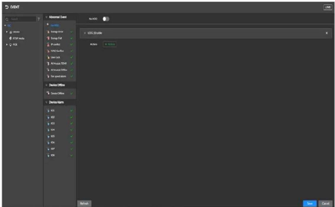
Step 4
Click

to

to enable the No-HDD alarm.
Step 5 Set alarm linkage events.
Click 🧠️ Action and select Buzzer, LOG, Device Alarm Output or Email to enable corresponding alarm linkage, as shown in Figure 9-56. See Figure 9-14 for descriptions of alarm linkage.

For example, if you select IPC Alarm Output, you can set the output port and delay time.
Figure 9-56 Actions
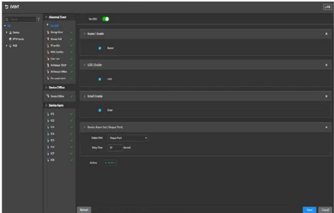
Table 9-14 Descriptions of alarm linkage events
| Alarm linkage events | Description Preconditions | |
| Recording | When an alarm is triggered, the system links with the selected camera to take recording. | Surveillance devices, such as IPC, are added. |
| Snapshot | When an alarm is triggered, the system links with the camera to take snapshots. | - |
| Buzzer | When an alarm is triggered, the system gives the buzzer. | - |
| Log | When an alarm is triggered, the system records alarm information in the log. | - |
| When an alarm is triggered, the system sends alarm emails to all added receivers. | Emails configuration completed. | |
| Local alarm output | When an alarm is triggered, the system links with the alarm output device to trigger the alarm. | The Device is connected with an alarm output device. |
| IPC alarm output | When an alarm is triggered, the system links with the alarm output device to trigger the alarm. | IPC is added and connected to the alarm output device. |
Step 6 Click Save.
9.5 System
You can make configurations of the system such as general parameters, schedule, time and more.
9.5.1 Setting System Parameters
You can make configurations such as setting the system language, user logout time, and mouse moving speed.
Step 1
Click

on the homepage, and select SYSTEM > SYSTEM.
The system displays System interface. See Figure 9-57.
Figure 9-57 System

Step 2 For more details about parameters, see Table 9-15.
Table 9-15 Descriptions of system parameters
| Parameter Description | |
| Language Set the system language. | |
| Video standard | Select the video standard.PAL is mainly used in China, Middle East, and Europe.NTSC is mainly used in Japan, USA, Canada, and Mexico.[IMAGE]Video standard is a technical standard used to process video and audio signals. PAL and NTSC vary in encoding and decoding methods, and field scanning frequency. |
| User logout time | Set the user logout time. When you remains inactive for a specified period or the device exceeds the set value. After auto logout, the user needs to login again to operate.If theUser Log-out Timeis set toNon cancellation,the system does not automatically log out. |
| Live view control | After selecting this function, you can enter local live view without entering the username and password. |
| Mouse moving speed | Set the mouse moving speed ion the local interface. |
Step 3 Click Save.
9.5.2 Setting Time
Set the system time for the Device and select whether to enable NTP as necessary. After enabling NTP, the Device automatically synchronizes time with the NTP server.
Step 1 Select SYSTEM > TIME.
The system displays Time interface. See Figure 9-58.
Figure 9-58 Time

Step 2 For more details about parameters, see Table 9-16
Table 9-16 Descriptions of system parameters
| Parameter Description | |
| Time | Time and date Set the date and time of the system. You can manually set the system time, or set the Device to automatically synchronizes time with the NTP server.Manual setting: SelectManual Settingand set the correct date and time.Sync with the Internet time server: SelectSync with Internet Time Server, enter the IP address or domain of the NTP server, and then set and then set Auto Sync Time Interval. |
| Time and Date Format | Settings Time and date format. |
| Time Zone | Select the Device time zone. |
| Auto Time Synchronization | After enabling this function, the Device checks the system time of the camera after every preset time interval. If the local Device time and the camera time are not the same, the time of the camera is automatically corrected. |
Step 3 (Optional) Setting DST.

DST is a system to manually regulate local time, which is designed to save energy consumption. If the country or region where this Device is located adopts the DST, you can enable DST to ensure that system time is correct.

Click

to

to enable DST.

Selec

OST


uding Week and Date.

Set th

t ti


nd time of the DST.
Step 4 Click Save.
9.5.3 Display Output
Enable the monitor, monitor resolution, refresh rate of the connected device.
Step 1 Select SYSTEM > Display Output.
Figure 9-59 Display Output

Step 2 Select the output port and the main and profile views.
[Non-Text]
It displays that output here corresponds to the video output interface on the rear panel of the device, display output 1 corresponds to DVI1, and display output 2 corresponds to DVI2.
Step 3 For more details about output mode and resolution, see Table 9-17.
Table 9-17 Display Output Descriptions
| Parameter Description | |
| Output mode | Security screening mode and Monitor mode are selectable.● Security screening mode: Display the process of baggage security screening and the AI analysis result of suspect items.● Monitor mode: Display the live view. |
| Resolution | The default value is 1920*1080@60FPS. |
| Image Setting | Set the image enhancement effect for the current output screen.In automatic mode, the screen is displayed according to the enhancement effect of the actual operation.Select image enhancement effects, including 13 image enhancement modes such as black and white and partial enhancement. If you select the black and white mode, the screen will display the black and white effect by default. In live view status, the image enhancement operation on will not take effect. |
Step 4 Set display area. For more details about parameters, see Table 9-18.

When connected to the single-view devices, security screening mode and monitoring mode by default; when connected to the dual-view devices, both security screening mode by default.
Table 9-18 Display area descriptions
| Mode | Parameter | Description |
| Security Screening Mode | Scanned Baggage Record | After enabling the function, the live view interface displays scanned baggage images. Up to 100 baggage can be displayed.ClickSettingto set the danger level of the display item. |
| Add Channels | Add a video channel to the baggage security screening video to view real-time video at the same time.Click+, select the video channel, clickOK. | |
| Operation Bar | After selecting the function, the live view interface displays operation bar. Click the correspondingSetting, and the system displays Figure 9-60 set the operation bar.Drag the frequently used functions from the function list to the frequently used function area for daily use.In the custom function area, clickat the lower right corner and select the image enhancement effect, as shown in Figure 9-61. ClickOK. The settings correspond to the functions of F1, F2, and F3 keys on the keyboard. | |
| Status Bar | After enabling the function, the live view interface displays the status bar. | |
| Monitoring Mode | Window Split Method | Select  method. method. |
| Add Channels | Click  corresponding video channel displayed on the live view interface. corresponding video channel displayed on the live view interface. |
Figure 9-60 Operation bar settings(1)

Figure 9-61 Operation bar settings(2)
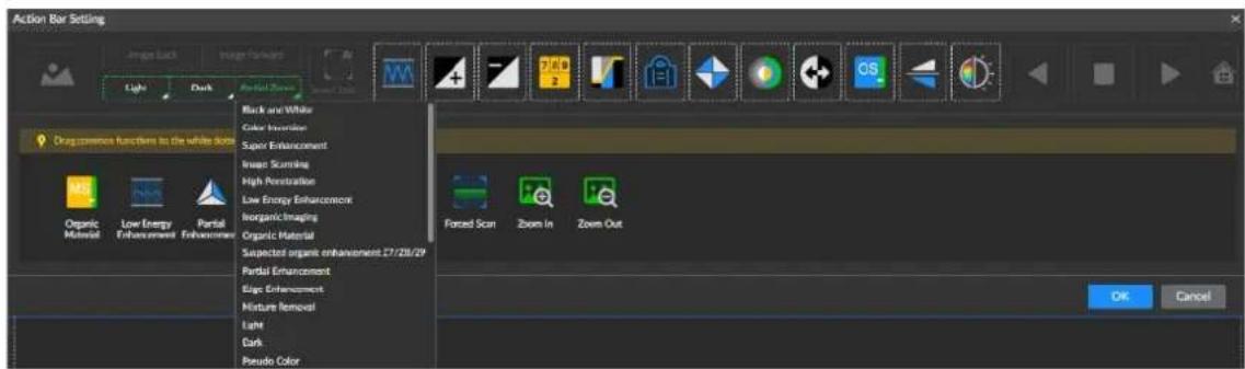
Step 5 Click Save.
9.5.4 Setting Schedule
Create a schedule of valid range of time. This schedule can be directly used when you configure arm/disarm period of alarm and recording. The system only implements these settings during the valid period of the calendar.
Step 1 Select SYSTEM > SCHEDULE > SCHEDULE.
The system displays SCHEDULE interface. See Figure 9-62.
Figure 9-62 Schedule
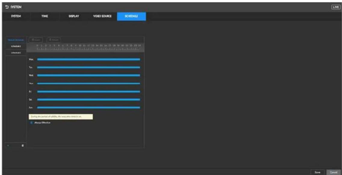
Step 2 Add Schedule
1) Click.

The system displays Add schedule interface. See Figure 9-63.
Figure 9-63 Add Schedule
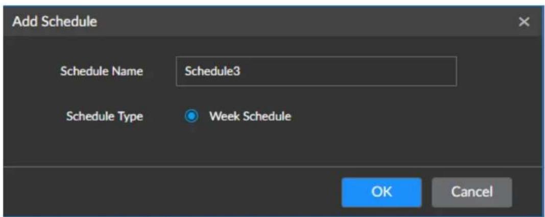
1) Set Schedule Name.
2) Click OK to save the settings.

Select the added schedule and click

to delete the selected schedule.
Step 3 Select the way of setting a valid range of time, from two options Always Effective and Customize.
Step 4 Set valid period of schedule.
- Click the blue area and is displayed. Drag to adjust the start time and end time of the valid period.
- Hold any of the vacant point on the time bar and drag rightward to add a new valid period.
- Click Clear to clear all the valid periods in the current schedule.
- Select a certain valid period and click Delete to delete the selected period.

• This step is required only when Custom is selected.
• Each schedule supports up to 50 effective time ranges.
• The blue area on the time axis shows the effective time.
Step 5 Click Save.
9.6 Account Management
User management of the Device includes the management of individual user and user group, whose basic information can be managed. To conveniently manage the user, we recommend the general user authorities shall be lower than high-level user authorities.

- To guarantee the safety of the Device, operations (such as adding or deleting a user) on the Account interface require entering the correct login password.
- After a correct login password is entered on Account interface, if you do not close Account interface, you can do other operations directly. If you close the interface and enter it again, you shall enter the correct login password again. The actual interface shall prevail.
9.6.1 User Group
Different users might have different authorities to access the Device. You can divide the users into different groups. It is easy for you to maintain and manage the user information.
- The system allows for creating up to 64 user groups. User group name supports maximum 64 characters.
- In default settings, the system has these user accounts: maintainer, operator, and admin; the admin user group cannot be deleted.
- New user group can only be created under the root.
9.6.1.1 Adding User Group
Create user groups to facilitate user management as needed.
Step 1 Click on the homepage, and select Account. The system displays User Management interface.
Step 2 Select a root from the list on the left and click . The system displays Input Password interface. See Figure 9-64.
Figure 9-64 Input password

Step 3 Enter the password of the admin user and click OK. The system creates a user group and display Attribute interface. See Figure 9-65.
Figure 9-65 Attribute
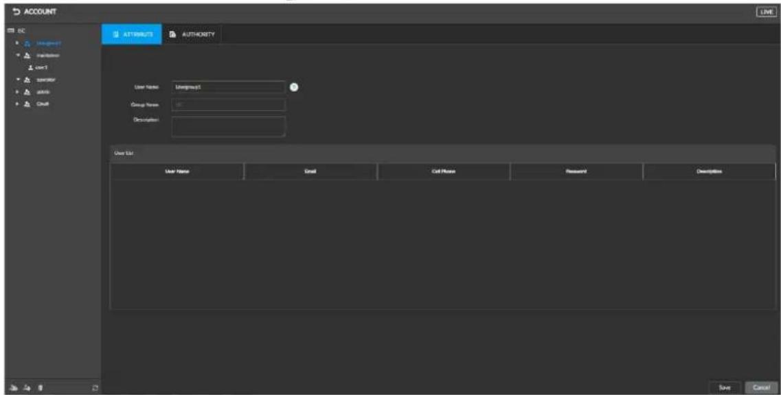
Step 4 For more details about parameters, see Table 9-19.
Table 9-19 User management parameters
| Parameter Description | |
| Name | Set user group name.A user group name can contain up to 64 characters consisting of letters, numbers, and special characters (including " _ ", "@", ".). |
| Group name | Shows the organization node of the user group. The system automatically recognizes the group name. |
| Set the email address of the user group. | |
| Description | Enter the descriptions of the user group. |
| User list | Displays the user information under the user group. |
Step 5 Setting user group authority.
1) Click the AUTHORITY.
The system displays AUTHORITY interface. See Figure 9-66.
Figure 9-66 Authority

2) Set user group authority based on your actual needs.

• indicates the corresponding authority is enabled.
- Click the check box at the top of the authority list (such as (7) Management) and all authorities in this list are selected.
Step 6 Click Save.
9.6.1.2 Deleting User Group

- A user group can be deleted only when it has no users.
• The admin user group can never be deleted.
On the Account interface, select a user group and click 📄 to delete the selected user group.
9.6.2 User Permission
9.6.2.1 Admin
All permissions are enabled by default.
9.6.2.2 Operator
Figure 9-67 Operator permission

9.6.2.3 Maintainer
Figure 9-68 Maintainer permission

9.6.3 User
The Device user can access and manage the Device. The admin account is the default administration user of the system.
9.6.3.1 Adding User
You can add multiple users as needed and make sure that a user only has access to resources within own authority.

User authorities adopt the user group authority settings. It is read-only.
Step 1 Click on the homepage, and select Account.
Step 2 Select the admin user group or a new user group, and click

The system displays Attribute interface. See Figure 9-67.
Figure 9-69 Attribute
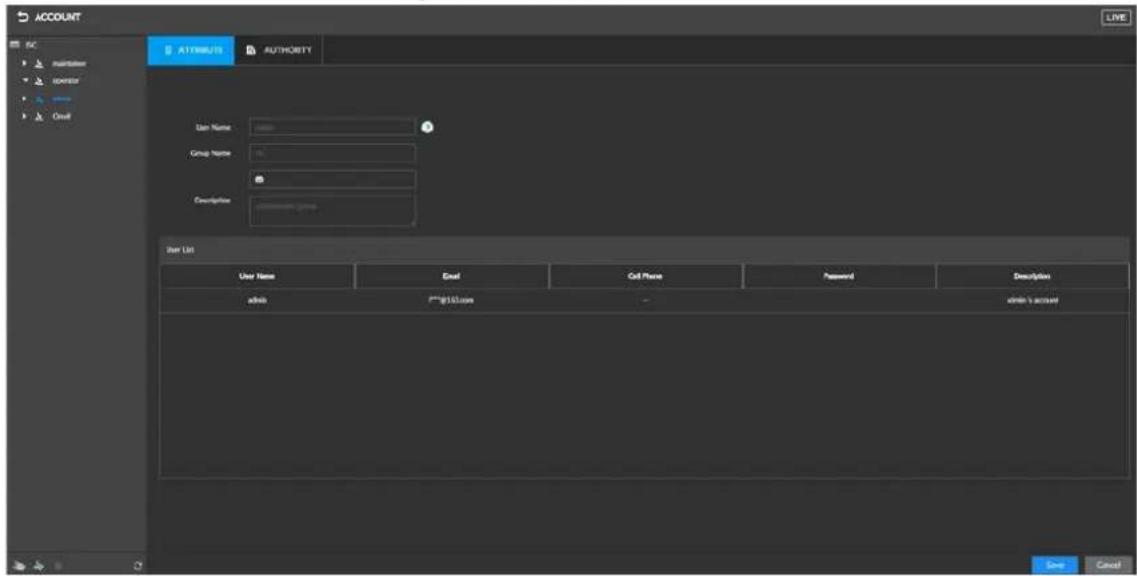
Step 3 For more details about parameters, see Table 9-20.
Table 9-20 User management parameters
| Parameter Description | |
| Name | Set user name.A user name can contain up to 31 characters consisting of letters, numbers, and special characters (including " _ ", "@", "."). |
| Group name | Shows the organization node of the user. The system automatically recognizes the group name. |
| Password | Set and confirm the User password. |
| Confirm password | ● The password can consist of 8 to 32 non-blank characters and contain at least two types of characters (excluding "", "", ";", ";", "&"). Set a strong password according to the feedback on password strength.● Hold the mouse over [icon] and the password becomes visible. Release the left mouse button or move the mouse pointer elsewhere, and the password become invisible again. |
| Set the email address of the user. | |
| Description | Enter the descriptions of the user. |
Step 4 (Optional) Click the AUTHORITY and set user authority. The system displays AUTHORITY interface. See Figure 9-68.

By default, the user inherits all authorities of its user group.
Figure 9-70 Authority
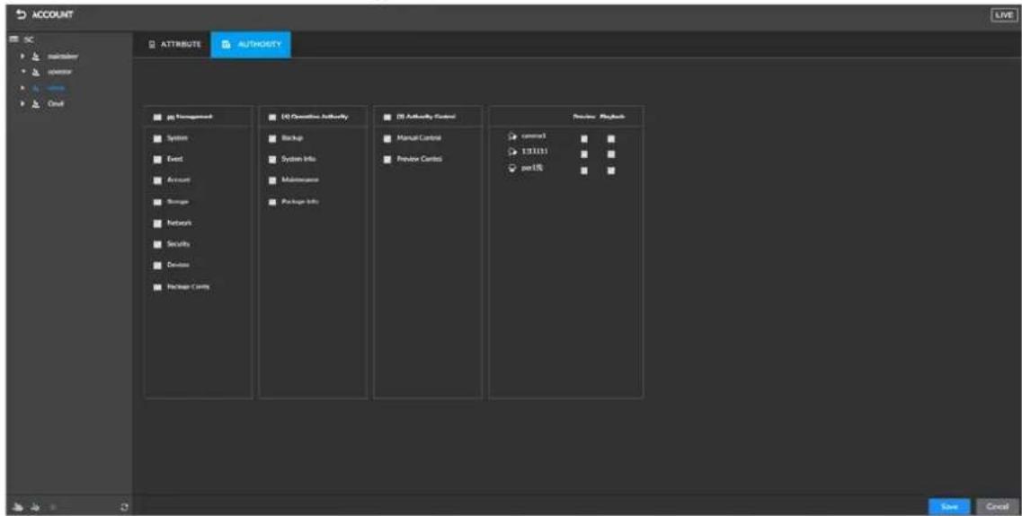
Step 5 Click Save.
9.6.3.2 Modifying User
A user account with user management authority can modify its own information and information of other users.
Step 1 Select Account. The system displays User Management interface.
Step 2 Select the target user for password modification.
Step 3 Modify user password.

Another way to modify password is to click admin at the lower-left corner of the interface and select Modify Password.

The system displays Input Password interface. See Figure 9-69.
Figure 9-71 Input password

2) Enter the password of the admin user and click OK.
The system displays Modification Password interface. See Figure 9-70.
Figure 9-72 Changing password.

3) Set and confirm the password.
4) Click OK.
Step 4 Set other user parameters, see Figure 9-20.

The username and user group of this user cannot be modified.
Step 5 Click Save.
9.6.3.3 Deleting User
On the Account interface, select a user, and then click 📄 to delete the selected user.
9.6.3.4 Resetting Admin Password
A lost admin login password can be reset by using the reserved email or security questions.
Step 1 Go to the login interface, see Figure 9-71.
Figure 9-73 Login Interface

Step 2 Click Forgot Password?
The system displays prompt interface, see Figure 9-72.
Figure 9-74 Prompt interface

Step 3 Click OK.
- If you have reserved an email, use the email to retrieve the password.
- If no email is reserved, set one and click Next.
Step 4 Reset the login password.
• Retrieving password with email
Follow onscreen instructions to scan the QR code, get the security code sent to the email you reserved, and then enter this security code.

Scanning the same QR code can get two security codes at most. To get another security code, refresh the QR code interface.
◇ The security code is valid for 24 hours.
- Retrieving password with security questions. Click the Reset Type drop-down box, and select Security Questions. The Security Questions interface is displayed. Select a security question and enter the preset corresponding answer correctly in the Answer text box.
Step 5 Click Next.
The system displays Setting new password interface.
Step 6 For more details about parameters, see Table 9-21.
Table 9-21 Descriptions of password parameters
| Parameter Description | |
| User | The default username is admin. |
| Password | The password should consist of 8 to 32 non-blank characters and contain at least two types of characters among upper case, lower case, number, and special characters (excluding "", "", "", :, ", &")。 Please set a high-security password according to the password strength prompt. |
| Confirm password | |
| Prompt question | After setting the Prompt Question, move the mouse pointer over i on the login interface. The system displays the prompt question you have set to help you recall the password. |
Step 7 Click OK.
The login interface is displayed and you can log in with the new password.
9.6.4 ONVIF User
When a camera is connected with the Device by the ONVIF protocol, you need to use the verified ONVIF account.

- By default, the system has three ONVIF user groups (admin, user, and operator) and does not allow manually creating an ONVIF user group.
- Directly adding users to the Onvif user group is not allowed.
9.6.4.1 Adding ONVIF User
Step 1
Click

on the homepage, and select Account.
The system displays User Management interface.
Step 2
Select user groups under Onvif.
The system displays Attribute interface of the ONVIF User group. See Figure 9-73.
Figure 9-75 Attribute of ONVIF user group

Step 3 Click.

The system displays Input Password interface. See Figure 9-74.
Figure 9-76 Input password

Step 4 Enter the login password of the current user, and then click OK. The system displays Attribute interface. See Figure 9-75.
Figure 9-77 Attribute of ONVIF user

Table 9-22 Descriptions of ONVIF user parameters
| Parameter Description | |
| Name | Set user name of ONVIF.ONVIF user name can contain up to 31 characters consisting of letters, numbers, and special characters (including " _ ", "@", "."). |
| Group name | Shows the organization node of the user. The system automatically recognizes the group name. |
| Password | Set the password of ONVIF user.The password can consist of 8 to 32 non-blank characters and contain at least two types of characters (excluding "", "", "," :, " & ") ). Set a strong password according to the feedback on password strength. |
| Confirm password | |
| Description | Enter the descriptions of the ONVIF user. |
Step 5 Click Save.
9.6.4.2 Deleting ONVIF User

The admin user can never be deleted.
Step 1 Click on the homepage, and select Account. The system displays User Management interface.
Step 2 Click the ONVIF user and then click . The system displays Input Password interface. See Figure 9-76.
Figure 9-78 Input password
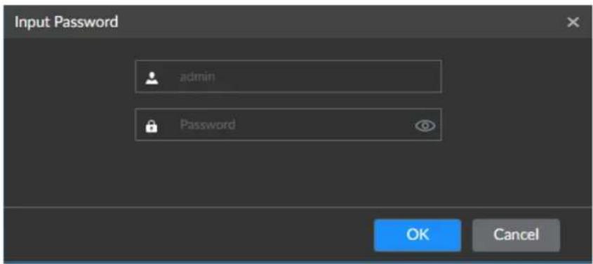
Step 3 Enter the login password of the admin user and click OK. The system displays the prompt interface.
Step 4 Click OK.
9.7 Security Management
9.7.1 Setting IP Access Authority
Set the IP host allowed to access the Device to enhance security for the network and data.
Step 1 Click on the homepage and then select SECURITY > IP ACESS AUTHORITY. The system displays IP ACESSAUTHORITY interface.
Figure 9-79 IP access authority
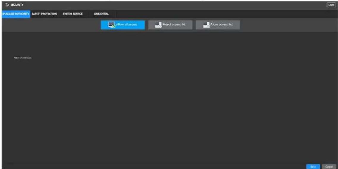
Step 2 Select the method to control IP access authority.
- Click Allow all access, and all IP hosts in the same LAN can access the current Device.
- Click Reject access list and add an IP host list. The IP host in the list is not allowed to access the current Device.
- Click Allow access list and add an IP host list. Only the IP host in the list is allowed to access the current Device.
Step 3 Adding IP host.

The following procedures are needed only when you clicked Reject access list or Allow access list.
1) Click Add.
The system displays Add interface.
Figure 9-80 Adding IP host

2) Select Add Type and set the IP address or MAC address of the IP host.
- If selecting Single IP, enter the IP address of the IP host.
- If selecting IPV6 addr, enter the IP range and add multiple IP hosts within this range to the list.
- If selecting MAC, enter the MAC address of the IP host.
3) Click OK to add the IP host.
The system displays added IP host list. See Figure 9-79.

- Click Add to add more IP hosts.
- Click 📋 to edit IP host.
- Select an IP and click Delete to delete the IP host.
Figure 9-81 IP host list

Step 4 Click Save.
9.7.2 Setting Safety Protection
You can set the login password lock strategy once the login password error has exceeded the specified threshold. System can lock current IP host for a period of time.
Step 1 Select SECURITY > SAFETY PROTECTION.
The system displays Safety protection interface.
Figure 9-82 Safety protection (1)

Step 2
Click

to

to enable safety protection.
- Remote: When you log in to device on web interface, once the login password error has exceeded the threshold, system locks the IP host for a period of time.
- Local: When you log in to device on local interface, once the login password error has exceeded the threshold, system locks the IP host for a period of time.
Step 3 Set the most suitable lockup strategy based on actual needs.
Step 4 Click Save to save the settings.
Once the IP host has been locked, you can view the locked IP host on the list. Select an IP
host, click Unlock or the corresponding 🔍 o unlock this IP host.
9.7.3 Setting System Service
Step 1 Select SECURITY > SYSTEM SERVICE.
The system displays System interface.
Figure 9-83 System service

Step 2 Enable or disable the system service based on the actual needs.
Table 9-23 System service
| System service Description | |
| SSH | After enabling this function, you can access the Device through the SSH protocol to complete system adjustment and IP settings. SSH is disabled by default. |
| Password reset | After this function is enabled, a lost admin login password can be reset by using the reserved email or security questions.Password Resetis disabled by default.If this is not enabled, the password can only be reset on local interface. |
| CGI service | When CGI is enabled, a third-party platform can connect to this Device through the CGI protocol. |
| ONVIF service | When ONVIF is enabled, other devices can connect to this Device through the ONVIF protocol. |
| Private protocol authentication mode | Set private protocol authentication mode, security mode and compatibility mode are selectable.● Security mode: System uses safer private protocol.● Compatibility mode: System is compatible with various private protocols. |
Step 3 Click Save.
9.7.4 Setting Firewall
Set different firewall types to guarantee the cyber security. Disable PING and half-open connection.

Disable PING: No reply to PING request.
Disable half-open connection: Enable the function to prevent the device from being attacked by hackers and not working properly.
Step 1 In the live view interface, click , select SECURITY>FIREWALL
Step 2 Click to disable PING and half-open connection as needed.
Figure 9-84 Firewall

Step 3 Click Save.
9.7.5 HTTPS
HTTPS guarantees the security of user information, device security, and data communication with reliable and stable technological means. After installing the certificate, you can use the HTTPS on the PC to access the Device.
9.7.5.1 Certificate Installation
The system provides two certificate installation methods as follows. Select the most suitable method based on your own needs.
• Installing manually created certificate.
• Installing signature certificate.
9.7.5.1.1 Installing Created Certificate
Install certificates by manually creating them, including creating certificates on the Device, and downloading and installing root certificates from PC.

- For first-time use of HTTPS or after changing the IP address of the Device, you need to create server certificates and install root certificates.
- After creating server certificate and installing root certificate, if you use another PC to log in to the Device web, download and install root certificate on the new PC, or copy the downloaded certificate to the new PC.
Step 1 Select SECURITY > CREDENTIAL.
The system displays Credential interface.
Figure 9-85 Credential (1)

Step 2 Create certificate on the Device.
1) Click Create Certificate.
The system displays Creating Certificate interface.
Figure 9-86 Creating Certificate

2) Set Country, IP/Domain, Term of Validity, and other information as needed.

● Country, IP/Domain, Term of Validity are required; others are optional.
• In IP/Domain, fill the IP or domain name of the Device.
3) Click OK.
The system starts creating certificate and displays information of the created certificates.
Figure 9-87 Credential (2)

Step 3 Download root certificate.
1) Click.
Download
The Opening ca.crt interface is displayed.
2) Click Save File and select the path to store files.
3) Click Save.
The system starts downloading certificate file.
Step 4 Install the root certificate on the PC.
1) Double-click the certificate file. The Open File-Security Warning interface is displayed.
2) Click Open. The system display Certificate interface.
3) Click Install Certificate. The system display Certificate Import Wizard interface.
4) Follow on-screen instructions to import certificate. The system returns to the Certificate interface.
Step 5 Click OK to complete certificate installation.
9.7.5.1.2 Installing signature certificate
Install signature certificates by uploading them.
Preconditions
Before installation, make sure you have obtained safe and valid signature certificate.
Procedures
Step 1 Select SECURITY > CREDENTIAL.
The system displays Credential interface.
Step 2 Click Install Signature Certificate.
The system display Install Signature Certificate interface.
Figure 9-88 Installing signature certificate

Step 3 Click Browse to select the certificate and certificate key files.
Step 4 Click Install.
The system starts installing certificates. Certificate information is displayed after installation.
Step 5 Install the root certificate on the PC. For details, see Step 4 in "9.7.5.1.1 Installing Created Certificate".

This root certificate is the one obtained with signed certificate.
9.7.5.2 Enabling HTTPS
After installing the certificate and enabling HTTPS, you can use the HTTPS on the PC to access the Device.
Step 1 Select SECURITY > CREDENTIAL.
The system displays Credential interface.
Step 2 Click to enable HTTPS.
Step 3 Click Save to save the settings.
Step 4 After saving the settings, you can use HTTPS to log in to the web interface.
Enter https://IP address: port on the address bar of the browser, and then press Enter. The login interface is displayed.

• IP address is Device IP or the domain name.
- Port refers to device HTTPS port number. If the HTTPS port is the default value 443, you can directly access Device by entering https://IP address.
9.7.5.3 Uninstalling Certificate
Uninstall the installed certificate.

After uninstallation, the HTTPS function becomes unusable.
Step 1 Select SECURITY > CREDENTIAL.
The system displays Credential interface.
Figure 9-89 Credential (1)
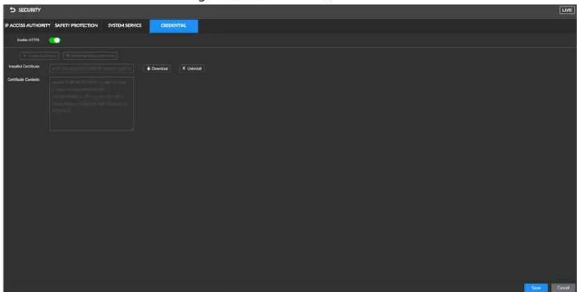
Step 2 Click Uninstall.
The system displays prompt interface.
Figure 9-90 Prompt interface

Step 3 Click OK to uninstall the installed certificate.
10 Operation and Maintenance Management
You can operate and maintain the Device running environment to guarantee proper operation.
10.1 Log Search
Logs record all kinds of system running information. To ensure normal operation of the system, regularly view the log and fix the problems in time.

Clear the logs may make it impossible to find out the cause of the system abnormality, please operate carefully.
10.1.1 System Log
You can search or export the system log, including the running status log, file management log, hot spare HDD log, HDD detection log, and timed task log.
Step 1 Click on the homepage, and select MAINTAIN > LOG > System.
The system displays System Log interface.
Step 2 Set the search conditions, including level, type, and date of the system log.

Click Reset if you want to restore the search conditions to default settings.
Step 3 Click Search.
The system displays search results.
Figure 10-1 System log

- Insert the USB storage device, and then click 📋 to export the log information.
- Click Clear all to clear all system logs.
10.1.2 User Operation Log
You can search or export user operation log, including user operations or settings.
Step 1 Select MAINTAIN > LOG > User Operation.
The system displays User Operation Log interface.
Step 2 Set the search conditions, including type, username, and date.

- Click Reset if you want to restore the search conditions to default settings.
- Click » to set the devices you want to search.
Step 3 Click Search.
The system displays search results.
Figure 10-2 User Operation Log

- Insert the USB storage device, and then click ↗ to export the log information
- Click Clear all to clear all user operation logs

Clear the logs may make it impossible to find out the cause of the system abnormality, please operate carefully.
10.1.3 Event Log
You can search or export the alarm event log.
Step 1 Select MAINTAIN > LOG > Event.
The system displays Event Log interface.
Step 2 Set the search conditions, including type, username, and date.

Click Reset if you want to restore the search conditions to default settings.
Step 3 Click Search.
The system displays search results.
Figure 10-3 Event Log

- Choose the log and click 📄 to export the log information to the USB storage device.
- Click Clear all to clear all event logs.

Clear the logs may make it impossible to find out the cause of the system abnormality, please operate carefully.
10.1.4 Link Log
Query or export linkage log, including user log-out, session hijacking, session blasting, and more.
Step 1 Select MAINTAIN > LOG > Link.
The system displays Link Log interface.
Step 2 Set the search conditions, including type, username, and date.

Click Reset if you want to restore the search conditions to default settings.
Step 3 Click Search.
The system displays search results.
Figure 10-4 Link Log
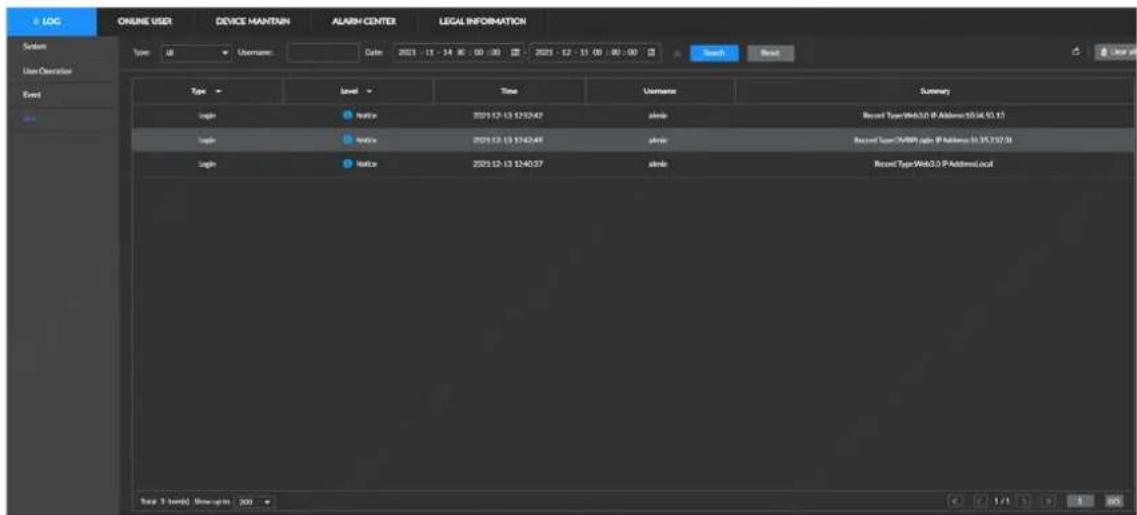
- Choose the log and click Export to export the log information to the USB storage device.
- Click Clear all to clear all link logs.

Clear the logs may make it impossible to find out the cause of the system abnormality, please operate carefully.
10.2 Online User
You can search the information of network user who remotely access the Device. A user can be blocked from accessing the Device for a period of time.

You cannot block yourself or admin user.
Step 1 Select MAINTAIN > ONLINE USER.
The system displays Online User.

The list displays the connected user information.
Figure 10-5 Online User

Step 2 Select the user you want to block and click Block.
The system displays Block interface.
Figure 10-6 Block

Step 3 Set the block time. The default setting is 30 min.
Step 4 Click OK to save the settings.
10.3 Maintaining Device
Device maintenance refers to operations such as rebooting the Device, restoring default settings, or system upgrades. These operations aim to clear failures or errors from the running system and make the Device work more efficiently.
10.3.1 Upgrade
You can upgrade the system version by importing upgrade files. Upgrades files in .bin format.

- During upgrading, do not disconnect from power and network, and reboot or shut down the Device.
- Make sure the update file is right. Improper upgrade file might result in device error.
10.3.1.1 Host Upgrade
Preconditions
The USB device with upgrade files is connected to the Device.
Procedures
Step 1 Select MAINTAIN > DEVICE MAINTAIN > Upgrade > Host.
The system displays Upgrade the host interface.
Figure 10-7 Host upgrade

Step 2 Click Browse and select the upgrade file.

Version upgrade, module upgrade and keyboard need to be done separately.
Step 3 Click Upgrade Now.
The system starts upgrading. After the upgrade, the Device automatically reboots.
10.3.1.2 Upgrading Cameras
Preconditions
The USB device with upgrade files is connected to the Device.
Procedures
Step 1 Select MAINTAIN > DEVICE MAINTAIN > Upgrade > Camera Upgrade.
The system displays Camera Upgrade interface.
Figure 10-8 Camera upgrade
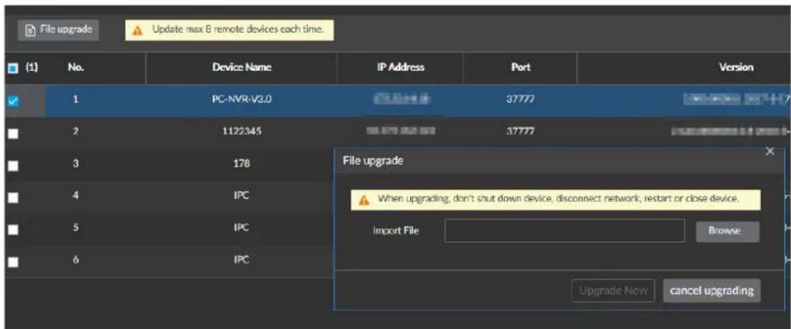
Step 2 Select the camera to be upgraded.
Step 3 Click File upgrade.

Close recording before upgrade; otherwise the upgrade might fail.
Step 4 Click Upgrade Now.
The system starts upgrading. The camera restarts automatically after the upgrade finishes.
10.3.2 Factory Default
If the Device runs slowly and has configuration errors, try restoring default settings.

All settings are lost if you restore default settings. Be careful.
Step 1 Select MAINTAIN > DEVICE MAINTAIN > Reset Default.
The system displays Reset Default interface.
Figure 10-9 Restoring default settings

Step 2 Click Factory Default.
The system starts restoring default settings. After the restoration, the Device automatically reboots.
10.3.3 Configure and Backup
You can export configuration files to a local PC or USB storage device for backup. When the configuration is lost due to abnormal operation, import a configuration backup to quickly restore system settings.
Importing Configurations
Step 1 Select MAINTAIN > DEVICE MAINTAIN > IMP/EXP.
The system displays IMP/EXP interface.
Figure 10-10 IMP/EXP interface

Step 2 Click Browse and select the configuration files that you want to import.
Step 3 Click Config Import.
Exporting Configurations
Click Config Export and you can export configuration files to a local PC or USB storage device. Saving path might vary according to interfaces you operate on, and the actual interface shall prevail.
- On local interface, you can select where to save files.

In local operations, connect the USB storage device to the Device.
- On web interface, files are stored in the default path set up in the browser.
10.4 Notification Center
Various unprocessed alarm massages are displayed in real time on the Notification Center interface.

There is an icon in front of each failure alarm.
Step 1 Select MAINTAIN > Notification Center.
The system displays Notification Center interface.
Step 2 Perform operations on notifications.
- Click Refresh to update alarm notifications.
- Restore notifications: Click Restore, and the Device automatically attempts to restore from X-ray failure.

Restoring is only available for X-ray failure.
10.5 Device Diagnosis
10.5.1 X-ray System Diagnosis
10.5.1.1 Detector Diagnosis
The detector diagnosis module displays the grayscale curve of detection points. You can click Start emission and Stop emission in X-ray Source Control to observe the curve amplitude, and determine whether the detector is in good quality and whether the position of each detection board is adjusted properly.
- Click Start emission, the X-ray is generated and the curve rises. Click Stop emission, the X-ray emission is stopped and the curve falls.
- Click Forward, Stop, and Backward, the conveyor rotates forward, stops, or rotates backward.
Curve judgment standards:
• The number of detection boards and the number detection points vary with the Devices.
- The curve amplitude shall be between 10000–30000. The whole curve is a relatively stable line chart.
10.5.1.2 X-ray Generator Diagnosis
Diagnose whether the voltage and current are normally displayed when X-ray is triggered normally for a preliminary judgment on the X-ray generator.
Figure 10-11 Profile view X-ray generator diagnosis

line
| Time (s) | Voltage (V) | Current (mA) | | :--- | :--- | :--- | | 0 | 0 | 0 | | 64 | 0 | 0 | | 138 | 0 | 0 | | 192 | 0 | 0 | | 254 | 0 | 0 | | 300 | 0 | 0 | | 364 | 0 | 0 | | 430 | 0 | 0 | | 497 | 0 | 0 | | 563 | 0 | 0 | | 630 | 0 | 0 | | 697 | 0 | 0 | | 764 | 0 | 0 | | 831 | 0 | 0 | | 908 | 0 | 0 | | 975 | 0 | 0 | | 1043 | 0 | 0 | The chart displays two line plots: the top plot shows 'Low Energy' (Y-axis, in volts) and the bottom plot shows 'Current' (Y-axis, in amperes). The X-ray generator is labeled below the charts. The data for 'Low Energy' and 'Current' are not plotted. The table below is a series table showing the 'Voltage' and 'Current' values at each time point. The 'Volume Control' and 'Touch off' columns are filled with 'Blue' and 'Red' respectively. The 'Contacter Belt Control' column is filled with 'Left', 'Stop', and 'Page'.
- Take 100100 series security screening machine as an example, currently the number of detector is 18, the interfaces might vary from different security screening machines according to its different number of detectors.
- Dual-view server: Click Main View or Profile View on the top of the interface, and you can switch the diagnosis and the ray sources of the two views.
- Single-view server: Only displays one view.
- Click Start emission, the X-ray is generated, and the voltage and current start to be displayed. Click Stop emission, the X-ray emission is stopped, and the voltage and current stop being displayed. The specific voltage and current vary from the settings of different models of devices.
- Click Forward, Stop, and Backward, the conveyor rotates forward, stops, or rotates backward.
10.5.2 IR Sensor Diagnosis
Diagnose the working status of the two pairs of IR sensors at the entrance and the other two pairs at the exit.
Step 1 Select MAINTAIN > Device Diagnosis > IR Sensor Diagnosis.
The system displays IR Sensor Diagnosis interface.
Figure 10-12 IR sensor diagnosis

Step 2 Test IR sensors.
- Test method 1: Block the IR sensors at the entrance with an opaque object, and there will be a square wave at high level at A side. The longer the blocking, the wider the square wave, which is normal. Use the same method to test B side.
- Method 2: Place an object to be inspected flat on the conveyor, and then click Forward. It is normal when there is a square wave at high level at A side. Click Backward. It is normal when there is a square wave at high level at B side.
Figure 10-13 IR sensor diagnosis


- A side represents the entrance direction, and B side represents the exit direction (nameplate side).
- The green line indicates power saving IR sensor, and the red line indicates package sensor inside the tunnel.
• Horizontal axis: Time.
• Vertical axis: Connection status. - Low level without blocking and high level with blocking.
• There is a high level pulse when an object passes.
10.5.3 Special Keyboard Diagnosis
Diagnose the working status of the external keyboard of the Device.
Step 1 Select MAINTAIN > Device Diagnosis > Special Keyboard Diagnosis.
The system displays Special Keyboard Diagnosis interface.
Figure 10-14 Special keyboard diagnosis
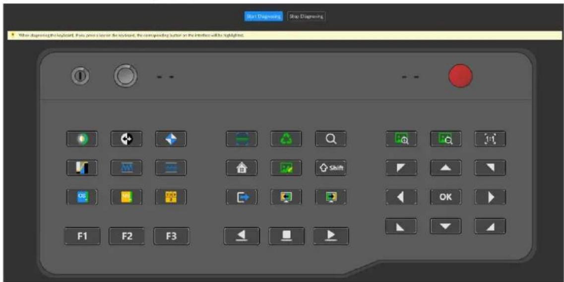
Step 2 Click Start Diagnosis.
The keyboard works normally as follows:
- Press a key on the physical keyboard, the corresponding button on the interface will light up.
- Long press a key on the physical keyboard, the corresponding button on the interface will keep lighting up.
- Release the key, the corresponding button on the interface restores to normal.

- Diagnosis of power button, key switch, and emergency stop button is not supported.
- Esc is different from other buttons, and the function of exit is not available. Press Esc on the keyboard, the corresponding button on the interface will light up, which means that the function is normal.
10.5.4 One-Click Diagnosis

Exit or cancel is not available during diagnosis.
Use one-click diagnosis to determine whether the key components of the Device work normally.
Step 1 Select MAINTAIN > Device Diagnosis > One-Click Diagnosis.
The system displays One-Click Diagnosis interface.

When one-click diagnosis is triggered for the first time, the system doesn't display corresponding report.
Figure 10-15 One-click diagnosis

Step 2 Click Start Diagnosis.
The system display prompts before starting diagnosis.
Figure 10-16 Confirmation information before starting diagnosis.
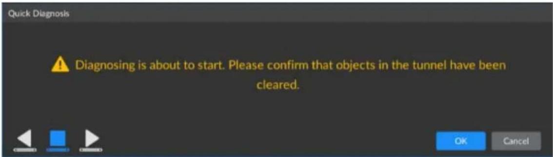
Step 3 Click OK to start diagnosis.
The system displays Diagnosis progress interface.
• indicates diagnosing.
• indicates to be diagnosed.
Figure 10-17 Diagnosis progress

Step 4 After diagnosis is completed, click View Report to view the report details.
Related Operations
- The list of one-click diagnosis reports is arranged in a reverse chronological order.
- Each page can display 30 or 50 reports. When the maximum display number of the page is exceeded, you need to turn pages for check.
10.6 Logout/Rebooting/Shutting
You can log out from the current user account, and reboot or shut the Device.

You can only use the local key to shut down the Device.
Logging out
On the homepage, click

and select Log Out.
Rebooting
On the homepage, click

select Reboot, and the system prompts confirmation
window. Click OK and the Device reboots.
Shutting

Directly plug off the power supply can result in the loss of unsaved files (recordings, pictures).
Method A as follows is recommended.
One-key shutdown, turn the key switch counterclockwise to the "OFF" state, the software exits, and the system power supply is disconnected.
11 FAQ2
11.1 The conveyor works normally, but the baggage image is not generated.
Possible Cause
• Abnormal scanning configuration of the device.
• Expired device license
Troubleshooting Procedures
- Check whether the current scanning configuration is single direction scanning. If it is set as single direction scanning and the package is reversed, the images of scanned image are not generated;
- Configuration: Select MENU> BAGGAGE MANAGEMENT > SECURITY SCREENING, set the scanning mode, the default mode is double direction scanning mode.
Figure 11-1 Set scanning direction

- If the device license expires, select MENU>MAINTAIN >DEVICE MAINTAIN>UPDATE to check the validity period of the license.
Figure 11-2 Check validity period of the license


If the errors cannot be eliminated according to the above procedures, please contact professional maintenance personnel.
11.2 The conveyor suddenly stops during the working process.
Possible Cause
- Power saving mode is on.
• Abnormal damage of the motor.
Troubleshooting Procedures
- If the power saving mode is on, the conveyor will automatically stop if no package passes within 15 seconds; select MENU>BAGGAGE>MANAGEMENT>SECURITY SCREENING to confirm whether the power saving mode is on. If it is on, turn it off.
Figure 11-3 Check the mode


If the errors cannot be eliminated according to the above procedures, please contact professional maintenance personnel.
11.3 No AI overlay after scanning baggage.
Possible Cause
- AI overlay is disabled.
- Check the detection config, partial prohibited items recognition enables.
- Expired device license.
Troubleshooting Procedures
- Go back to the live view interface to enable AI overlay.
Figure 11-4 Enable AI overlay

- Check the recognition switches of the prohibited items corresponded to the detection config enable or not. Each prohibited item can be recognized only when its recognition switch is on. Select MENU> BAGGAGE MANAGEMENT>DETECTION CONFIG.
Figure 11-5 Turn on the recognition swith
| No. | Disabled | Item Name | Class | Threshold | Text Color | Operate | |
| 1 | Cam | Danger | 58 | % | Red | ✓ | |
| 2 | Poremato Porematicons | Danger | 20 | % | Purple | ✓ | |
| 3 | Sydney-Can | Danger | 30 | % | Red | ✓ | |
| 4 | Knives | Danger | 40 | % | Red | ✓ | |
| 5 | Aer | Warning | 84 | % | Purple | ✓ | |
| 6 | Unknown | Danger | 40 | % | Red | ✓ | |
| 7 | Ignition oil | Warning | 43 | % | Purple | ✓ | |
| 8 | Nud Polish | Warning | 43 | % | Purple | ✓ | |
| 9 | Liquidite | Warning | 43 | % | Purple | ✓ | |
| 10 | Citrus beetles | Warning | 43 | % | Purple | ✓ | |
| 11 | Thermoc cup | Warning | 43 | % | Purple | ✓ | |
| 12 | Plastic toilet | Warning | 43 | % | Purple | ✓ | |
| 13 | Trembouts | Danger | 10 | % | Gray 11-12-13-14-15-16-17-18-19-20-21-22-23-24-25-26-27-28-29-30-31-32-33-34-35-36-37-38-39-40-41-42-43-44-45-46-47-48-49-50-51-52-53-54-55-56-57-58-59-60-61-62-63-64-65-66-67-68-69-70-71-72-73-74-75-76-77-78-79-80-81-82-83-84-85-86-87-88-89-90-91-92-93-94-95-96-97-98-99-100-101-102-103-104-105-106-107-108-109-110-111-112-113-114-115-116-117-118-119-120-121-122-123-124-125-126-127-128-129-130-131-132-133-134-135-136-137-138-139-140-141 142 143 144 145 146 147 148 149 150 151 152 153 154 155 156 157 158 159 160 161 162 163 164 165 166 167 168 169 170 171 172 173 174 175 176 177 178 179 180 181 182 183 184 185 186 187 188 189 190 191 192 193 194 195 196 197 198 199 200 201 202 203 204 205 206 207 208 209 210 211 212 213 214 215 216 217 218 219 220 221 222 223 224 225 226 227 228 229 230 231 232 233 234 235 236 237 238 239 240 241 242 243 244 245 246 247 248 249 250 - - - - - - - - - - - - - - - - - - - - - - - - - - - - - - - - - - - - - - - - - - - - - - - - - - - - - - - - - - - - - - - - - - - - - - - - - - - - - - - - - - - - - - - - - - - - - - - - - - - - | ||
- If the device license expires, select MENU>MAINTAIN>DEVICE MAINTAIN>UPDATE to check the validity period of the license.
Figure 11-6 Check the validity period of license


If the errors cannot be eliminated according to the above procedures, please contact professional maintenance personnel.

If the errors are not covered by this manual, please contact professional maintenance personnel.
Appendix 1 Dimension Diagram of Applicable Models
Appendix Figure 1-1 ISC-M100100D
![1966.0 [73,43] 1596.0 [62,44] 300.0 [11,81] 3910.0 [153,94] 4783.0 [167,13]](/content/2026/05/996920/images/6cf5dec29d01ccec4755d065c712ab3178bff34b5fd7cf09620842477f6dc02a.jpg)
![1007,0 [39,65] 1010,0 [39,70] 186,0 [73,43] 1796,0 [70,47]](/content/2026/05/996920/images/626cb310a2b0e8e66a28fa51225febd7a3418a98dbf9adbb574cd8f935d232a4.jpg)
![1790.0 [78,47] 1280.0 [50,36] 1021.0 [39,41] 1372.0 [54,02] 2697.0 [106,18]](/content/2026/05/996920/images/1acbea7d5e7b7cc3878422fe95b3ec217894072edf02d030f9be5f22df25c138.jpg)
Appendix Figure 1-2 ISC-M100100
![200.0 [78.74] 620.0 [36.22] 1950.0 [61.42] 200.0 [11.81]](/content/2026/05/996920/images/43a2df6a96f9c250f398bd3c91fba25081561cc5003539d0f466c9d2b0e76471.jpg)
![1300.0 [51,18] 1010.0 [39,76] 1006.0 [39,61] 1790.0 [70,47]](/content/2026/05/996920/images/66f7622083aa8a49183eb39e2ee4a82c51bde6c700275e2d6fa0571c51e46049.jpg)
![900.0 [35.43] 3599.0 [141.69] 700.0 [27.56]](/content/2026/05/996920/images/849897e788bfa4643fcb173f42549e485ce88a23f55f9960f2ea8a84e24cb93c.jpg)
Appendix Figure 1-3 ISC-M6550D
![4420.0 [174.02] 2319.0 [81,30°] 1480.0 [59,65°]](/content/2026/05/996920/images/641eae0af0f5fc46d8c37d4360249b027c50e16aaa8cbb69d2dba7bc7449b579.jpg)

Appendix Figure 1-4 ISC-M6550-V/ISC-M6550
![4113,9 [181,96] 2053,9 [80,86] 1230,0 [48,43]](/content/2026/05/996920/images/995811bbc98fd79484f899a398d1929513a971235c3249d7b3d5a38e5dfd3969.jpg)
![915,6 [36,05] 654,0 [25,75] 1403,0 [16,24] 602,0 [19,76] 806,0 [26,21]](/content/2026/05/996920/images/5a587f3087ca8446bb01397c828772976e0c5e6a8498a5b7fdd20c7e0b06fceb.jpg)
Appendix Figure 1-5 ISC-M6040
![2019.9 1103.152 1903.0 [76.46] 1156.0 145.51 650.0 78.10 650.0 78.56](/content/2026/05/996920/images/9cfea24bcc371bca0c089da51785ca17c958e7f779669456abf01e426803547b.jpg)
![870.0 [34.25]](/content/2026/05/996920/images/69eed298c4ebd623250c3158fcdfbb210bf4af1c582f45d82c209f1f884e8674.jpg)
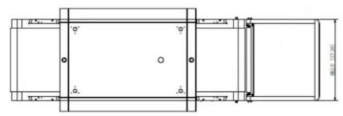
natural_image
Technical line drawing of a mechanical component with dimension annotations (no readable text or symbols)Appendix Figure 1-6 ISC-M5030
![1664.0 [65.51] 1040.0 [40.94] 1202.0 [47.32] 665.0 [26.18]](/content/2026/05/996920/images/8a082f6c1e056e64c37cb84a9a665935f6f1536b5a58a6ac508dc9f971f4cc5b.jpg)
![765.6 [30.14] 504.0 [19.84] 302.0 [11.89]](/content/2026/05/996920/images/0f54b0015009a47253d0155de434af315aa3f680009af91cc0ba6fff729e09aa.jpg)
Appendix 2 RAID
RAID is an abbreviation for Redundant Array of Independent Disks. It is to combine several independent HDDs (physical HDD) to form a HDD group (logic HDD).
Comparing with one HDD, RAID provides more storage capacity and data redundancy. The different redundant arrays have different RAID level. Each RAID level has its own data protection, data availability and performance level.
RAID Level
| RAID Level | Description Min. HDDs | |
| RAID 0 | RAID 0 is also known as Striping.RAID 0 is to save the continued data fragmentation on several HDDs. It can process the read and write at the same time, so its read/write speed is N (N refers to the HDD amount of the RAID 0) times that of a single HDD. RAID 0 does not have data redundant, so one HDD damage might result in data loss that cannot be restored. | 2 |
| RAID 1 | RAID 1 is also known as Mirror or Mirroring.RAID 1 data is written to two HDDs equally, which guarantee the system reliability and can be repaired. RAID 1 read speed is almost close to the total volume of all HDDs. The write speed is limited by the slowest HDD. At the same time, the RAID 1 has the lowest HDD usage rate. It is only 50%. | 2 |
| RAID 5 | RAID 5 stores data and the corresponding parity check information to each HDD of the RAID 5 group. The data and corresponding parity check information are stored in different HDDs. If one HDD of the RAID 5 is damaged, the system uses the residual data and corresponding parity check information to restore damaged data. This guarantees data intactness. | 3 |
| RAID 6 | Based on the RAID 5, RAID 6 adds one parity check verification HDD. By adopting different algorithms, the two mutually independent parity systems guarantee high data reliability, to the point that even damages to two HDDs at the same time would not result in data loss. Compared to RAID 5, the RAID 6 needs to allocate larger HDD space for parity check information, so its read/write is even worse. | 4 |
| RAID 10 | As the combination of RAID 1 and RAID 0, RAID 10 is strong in reading and writing data and guarantees data security. It uses the highly efficient reading and writing performance of RAID 0 and the powerful data protection and restoration capacity of RAID 1. However, RAID 10 is equally low in usage efficiency as RAID1. | 4 |
RAID Capacity
The calculation of RAID capacity is shown as follows.
capacityN refers to the HDD (with Min capacity) used to create the corresponding RAID.
| RAID Level | Total Capacity of N HDD |
| RAID 0 | Total capacity of current RAID group |
| RAID 1 Min (capacityN) | |
| RAID 5 | (N-1) × min (capacityN) |
| RAID 6 | (N-2) × min (capacityN) |
| RAID 10 (N/2) × min (capacityN) | |
| RAID 50 | (N-2) × min (capacityN) |
| RAID 60 | (N-4) × min (capacityN) |
Appendix 3 Total HDD Capacity Calculation
HDD capacity calculation formula:
Total HDD capacity (M) = Number of channels× recording time (h) × Used HDD space each hour (M/h)
The equation for calculating the recording time can be obtained through above equations.
$$ \text { Recording time(H) } = \frac {\text { Total HDD capacity(M) }}{\text { Number of channels } \times \text { Used HDD space each hour(M / H) }} $$
For example: The recording of a single channel uses 200 M HDD space per hour. Use 4-channel device to make 24-hour continuous recording in every day of one month (30 days), the required HDD space is: 4 channels×30 days×24 h×200 M/h = 576 GB. Typically five 120 GB HDDs, or four 160 GB HDDs are needed.
According to the above formula, at different stream values, recording file size of 1 channel in 1 hour is shown as follows (for your reference):
Appendix Table 1-1 Recording file size
| Max. Bit Stream | File Size | Max. Bit Stream | File Size |
| 96 K | 42 M | 128 K | 56 M |
| 160 K | 70 M | 192 K | 84 M |
| 224 K | 98 M | 256 K | 112 M |
| 320 K | 140 M | 384 K | 168 M |
| 448 K | 196 M | 512 K | 225 M |
| 640 K | 281 M | 768 K | 337 M |
| 896 K | 393 M | 1024 K | 450 M |
| 1280 K | 562 M | 1536 K | 675 M |
| 1792 K | 787 M | 2048 K | 900 M |
Appendix 4 Cybersecurity Recommendations
Cybersecurity is more than just a buzzword: it's something that pertains to every device that is connected to the internet. IP video surveillance is not immune to cyber risks, but taking basic procedures toward protecting and strengthening networks and networked appliances will make them less susceptible to attacks. Below are some tips and recommendations on how to create a more secured security system.
Mandatory actions to be taken for basic device network security:
1. Use Strong Passwords
Please refer to the following suggestions to set passwords:
• The length should not be less than 8 characters;
- Include at least two types of characters; character types include upper and lower case letters, numbers and symbols;
- Do not contain the account name or the account name in reverse order;
• Do not use continuous characters, such as 123;
• Do not use overlapped characters, such as 111;
2. Update Firmware and Client Software in Time
- According to the standard procedure in Tech-industry, we recommend to keep your device (such as NVR, DVR, IP camera) firmware up-to-date to ensure the system is equipped with the latest security patches and fixes. When the device is connected to the public network, it is recommended to enable the "auto-check for updates" function to obtain timely information of firmware updates released by the manufacturer.
• We suggest that you download and use the latest version of client software.
"Nice to have" recommendations to improve your device network security:
1. Physical Protection
We suggest that you perform physical protection to device, especially storage devices. For example, place the device in a special computer room and cabinet, and implement well-done access control permission and key management to prevent unauthorized personnel from carrying out physical contacts such as damaging hardware, unauthorized connection of removable device (such as USB flash disk, serial port),
2. Change Passwords Regularly
We suggest that you change passwords regularly to reduce the risk of being guessed or cracked.
3. Set and Update Passwords Reset Information Timely
The device supports password reset function. Please set up related information for password reset in time, including the end user's mailbox and password protection questions. If the information changes, please modify it in time. When setting password protection questions, it is suggested not to use those that can be easily guessed.
4. Enable Account Lock
The account lock feature is enabled by default, and we recommend you to keep it on to guarantee the account security. If an attacker attempts to log in with the wrong password several times, the corresponding account and the source IP address will be locked.
5. Change Default HTTP and Other Service Ports
We suggest you to change default HTTP and other service ports into any set of numbers between 1024\~65535, reducing the risk of outsiders being able to guess which ports you are using.
6. Enable HTTPS
We suggest you to enable HTTPS, so that you visit Web service through a secure communication channel.
7. MAC Address Binding
We recommend you to bind the IP and MAC address of the gateway to the device, thus reducing the risk of ARP spoofing.
8. Assign Accounts and Privileges Reasonably
According to business and management requirements, reasonably add users and assign a minimum set of permissions to them.
9. Disable Unnecessary Services and Choose Secure Modes
If not needed, it is recommended to turn off some services such as SNMP, SMTP, UPnP, to reduce risks.
If necessary, it is highly recommended that you use safe modes, including but not limited to the following services:
- SNMP: Choose SNMP v3, and set up strong encryption passwords and authentication passwords.
- SMTP: Choose TLS to access mailbox server.
- FTP: Choose SFTP, and set up strong passwords.
● AP hotspot: Choose WPA2-PSK encryption mode, and set up strong passwords.
10. Audio and Video Encrypted Transmission
If your audio and video data contents are very important or sensitive, we recommend that you use encrypted transmission function, to reduce the risk of audio and video data being stolen during transmission.
Reminder: encrypted transmission will cause some loss in transmission efficiency.
11. Secure Auditing
- Check online users: we suggest that you check online users regularly to see if the device is logged in without authorization.
- Check device log: By viewing the logs, you can know the IP addresses that were used to log in to your devices and their key operations.
12. Network Log
Due to the limited storage capacity of the device, the stored log is limited. If you need to save the log for a long time, it is recommended that you enable the network log function to ensure that the critical logs are synchronized to the network log server for tracing.
13. Construct a Safe Network Environment
In order to better ensure the safety of device and reduce potential cyber risks, we recommend:
- Disable the port mapping function of the router to avoid direct access to the intranet devices from external network.
-
The network should be partitioned and isolated according to the actual network needs. If there are no communication requirements between two sub networks, it is suggested to use VLAN, network GAP and other technologies to partition the network, so as to achieve the network isolation effect.
-
Establish the 802.1x access authentication system to reduce the risk of unauthorized access to private networks.
- Enable IP/MAC address filtering function to limit the range of hosts allowed to access the device.
ENABLING A SAFER SOCIETY AND SMARTER LIVING
- AI Dual-energy Security Screening Machine User's Manual
- Foreword
- General
- Application Scope
- Models
- Safety Instructions
- UI Icon/Button
- Privacy Protection Notice
- Revision History
- About the Manual
- Important Safeguards and Warnings
- Operation Requirements
- WARNING
- Electrical Safety
- CAUTION
- Table of Contents
- Foreword.... I
- Important Safeguards and Warnings.... III
- Part1: Product Introduction .... 1
- Overview.... 1
- Dimensions and Structure .... 3
- Part2: Operator....6
- Display and Control....6
- Basic Operations.... 20
- Image Processing and Live view.... 30
- Maintenance 47
- FAQ 49
- Part3: Administrator 52
- Daily Operations.... 52
- Settings 79
- Part1: Product Introduction
- Overview
- Introduction
- Functions
- Packing List
- Dimensions and Structure
- Dimensions
- Cable Ports
- Indicators
- Part2: Operator
- Display and Control
- Emergency Stop Button and Indicator
- Emergency Stop Button
- Power Indicators
- X-Ray Indicator
- Power Input
- Operation Keyboard
- Control Keys
- Function Keys
- Image Processing Keys
- Simple Operation Keyboard
- Control Keys
- Function Keys
- Image Processing Keys
- Basic Operations
- Power on
- Login and Logout
- Logging in
- Logging out
- Warming up
- Object Placement
- Object Scanning
- Shut down
- Basic Information Search
- Baggage Search
- Procedures
- Step 1
- Report Search
- Image Processing and Live view
- Live view
- Security Screening Mode
- Image Processing
- Color/Black & white
- Image Scan
- Organic Stripping
- Mixture Stripping
- Inorganic Stripping
- Inverse Color
- High Penetration
- Low Penetration
- Light/Dark
- Density Threat Alert Z7/Z8/Z9
- High Density Alert
- Zoom in/out
- Pseudo Color
- Vertical Flip
- AI Overlay
- Image Correction
- Force Scan
- Monitoring Mode
- Maintenance
- Cleaning External Surface of the Device
- Cleaning IR sensor on conveyor side
- Cleaning Display Screen
- Inspecting Conveyor
- Inspecting Lead Curtain at the Tunnel Inlet and Outlet
- Inspecting X-ray and Power Indicator
- Emergency Stop Button
- FAQ
- When the key switch is turned on and the power button is pressed, the indicator doesn't work and the Device cannot be powered on.
- Possible Cause
- Troubleshooting Procedures
- No generated images on the display screen
- Conveyor doesn't work
- Troubleshooting procedure
- Device automatically power off during running.
- Part3: Administrator
- Daily Operations
- Basic Settings
- Initialization Device
- Quick Configuration
- Step 2 Set IP address
- 3) Click OK.
- Step 3 Set DNS Server parameters.
- Step 4 Set the default NIC
- Step 5 Click Finish.
- Login and Logout
- Logging in to Local Interface
- Logging in to Web Interface
- Logging out
- Baggage Statistics
- Baggage Search
- Report Search
- Step 2 Set the query period, select the category of item, and then click Query.
- Step 3 Click Data and the system displays data in the form of report.
- Related Operations
- Export data:
- Voice Broadcast
- Uploading Voice File
- Step 1 Select BAGGAGE MANAGEMENT > VOICE BROADCAST.
- Configuring Voice Broadcast
- Voice Broadcast Rules
- Configuring Detection Parameters
- Configuring Suspect Item
- Security Screening
- Video Playback
- Playback
- Step 2
- Step 5 Click Search.
- Clipping Recording
- Image Playback
- Exporting Files
- Step 1 Select PLAYBACK.
- Step 2 Search recordings or images.
- Step 3 Select the thumbnails of recordings or images you want to export.
- Step 4 Click.
- Settings
- Device Management
- Managing the Device
- Device Attributes
- Storage Configuration
- Managing Camera
- Initializing Camera
- Step 2 Select DEVICE.
- Step 3 Click Add.
- Step 4 Click Start Search.
- Step 5 Select an uninitialized camera and click Initialize.
- 2) Click Next.
- 3) Set email.
- Step 7 Click Next.
- Adding Camera
- Smart Add
- Step 4 Adding a camera
- Manual add
- Step 5 Adding a camera
- Import CVS file
- Step 3 Fill in the template.
- Modifying IP Address of Camera
- Configuring Camera
- Attribute Settings
- Setting Connections
- Setting Video Parameters
- Setting OSD
- Storage Configuration
- Exporting Camera Information
- Viewing Device Connection Status
- Deleting Camera
- Network Management
- Modifying IP Address
- Setting Port Number
- Configuring Email
- Click
- Setting SWITCH
- Step 1 Select NETWORK > PORT.
- Step 3 Click Save.
- Configuring Auto Register
- Step 2 Click to auto enable auto register.
- Configuring UPnP
- Storage Management
- HDD
- View S.M.A.R.T Information
- Set Storage Strategy
- HDD Defragmentation
- Formatting
- RAID Management
- Creating RAID
- Step 3 Setting RAID Parameters.
- HDD Defragmentation
- Deleting RAID
- Formatting RAID
- Creating Hotspare HDD
- Step 2 Click Add.
- Step 3 Select the Creation Type of the hotspare HDD.
- Step 4 Select one or several HDD(s) and then click Next.
- Event
- Step 4
- System
- Setting System Parameters
- Setting Time
- Display Output
- Setting Schedule
- 1) Click.
- Account Management
- User Group
- Adding User Group
- Step 5 Setting user group authority.
- 1) Click the AUTHORITY.
- Deleting User Group
- User Permission
- Admin
- Operator
- Maintainer
- User
- Adding User
- Modifying User
- Deleting User
- Resetting Admin Password
- Step 2 Click Forgot Password?
- Step 3 Click OK.
- Step 4 Reset the login password.
- Step 5 Click Next.
- Step 7 Click OK.
- ONVIF User
- Adding ONVIF User
- Deleting ONVIF User
- Security Management
- Setting IP Access Authority
- ACCESS AUTHORITY SAFETY PROTECTION SYSTEM SERVICE ORIENTAL
- Step 3 Adding IP host.
- 1) Click Add.
- Setting Safety Protection
- to
- Setting System Service
- Setting Firewall
- HTTPS
- Certificate Installation
- Installing Created Certificate
- ACCESS AUTHORITY SAFETY PROTECTION SYSTEM SERVICE OCESSIONAL
- Download
- Installing signature certificate
- Preconditions
- Enabling HTTPS
- Uninstalling Certificate
- ACCESS AUTHORITY SAFETY PROTECTION SYSTEM SERVICE CREDENTIAL
- Operation and Maintenance Management
- Log Search
- System Log
- User Operation Log
- Event Log
- Step 3 Click Search.
- Link Log
- Online User
- Maintaining Device
- Upgrade
- Host Upgrade
- Upgrading Cameras
- Factory Default
- Configure and Backup
- Importing Configurations
- Exporting Configurations
- Notification Center
- Device Diagnosis
- X-ray System Diagnosis
- Detector Diagnosis
- X-ray Generator Diagnosis
- IR Sensor Diagnosis
- Step 2 Test IR sensors.
- Special Keyboard Diagnosis
- One-Click Diagnosis
- Step 2 Click Start Diagnosis.
- Step 3 Click OK to start diagnosis.
- Logout/Rebooting/Shutting
- Logging out
- Rebooting
- Shutting
- FAQ2
- The conveyor works normally, but the baggage image is not generated.
- The conveyor suddenly stops during the working process.
- No AI overlay after scanning baggage.
- Appendix 1 Dimension Diagram of Applicable Models
- Appendix 2 RAID
- RAID Capacity
- Appendix 3 Total HDD Capacity Calculation
- Appendix 4 Cybersecurity Recommendations
- Mandatory actions to be taken for basic device network security:
- Use Strong Passwords
- Update Firmware and Client Software in Time
- "Nice to have" recommendations to improve your device network security:
- Physical Protection
- Change Passwords Regularly
- Set and Update Passwords Reset Information Timely
- Enable Account Lock
- Change Default HTTP and Other Service Ports
- Enable HTTPS
- MAC Address Binding
- Assign Accounts and Privileges Reasonably
- Disable Unnecessary Services and Choose Secure Modes
- Audio and Video Encrypted Transmission
- Secure Auditing
- Network Log
- Construct a Safe Network Environment
Brand : Dahua Technology
Model : ISC-M100100
Category : Machine de contrôle de sécurité