DK7 - Microphone Earthworks - Free user manual and instructions
Find the device manual for free DK7 Earthworks in PDF.


| Product Type | High Definition Multi-microphone Drum System |
| Brand | Earthworks |
| Model | DK7 DrumKit™ |
| Included Microphones | 2 x SR25 (overheads), 4 x DM20 (toms/snare), 1 x SR20LS (kickdrum) |
| Included Accessories | 4 x RM1 RimMount™, 3 x SRW3 windscreens, 4 x PW1 windscreens, high-impact carrying case, user manual |
| SR25 Frequency Response | 20Hz – 25kHz |
| DM20 Frequency Response | 50Hz – 20kHz |
| SR20LS Frequency Response | 20Hz – 20kHz |
| Polar Pattern | Cardioid (all microphones) |
| SR25 Sensitivity | 10mV/Pa (-40dBV/Pa) |
| DM20 & SR20LS Sensitivity | 8mV/Pa (-42dBV/Pa) |
| Power Requirements | 24-48V Phantom Power @ 10mA |
| Maximum SPL | 150dB SPL (all mics) |
| S/N Ratio | 74dB A-weighted |
| Output | XLR (pin 2+), balanced |
| Output Impedance | 200Ω balanced (between pins 2&3) |
| SR25 Dimensions | Length: 6.5 in (165mm), Diameter: 0.860 in (22mm) |
| DM20 Dimensions | Length: 11.12 in (282.44mm), Diameter: 0.860 in (22mm); Gooseneck: 4.75 in (120.65mm) x 0.375 in (9.53mm) |
| SR20LS Dimensions | Length: 7.57 in (192.2mm), Diameter: 0.860 in (21.8mm) |
| SR25 Weight | 0.35 lb (160g) |
| DM20 Weight | 0.55 lb (0.25kg) |
| SR20LS Weight | 0.36 lb (164g) |
| Warranty | Limited warranty (parts and labor) - register at earthworksaudio.com/register |
| Country of Manufacture | USA |
Frequently Asked Questions - DK7 Earthworks
User questions about DK7 Earthworks
0 question about this device. Answer the ones you know or ask your own.
Ask a new question about this device
Download the instructions for your Microphone in PDF format for free! Find your manual DK7 - Earthworks and take your electronic device back in hand. On this page are published all the documents necessary for the use of your device. DK7 by Earthworks.
USER MANUAL DK7 Earthworks

Inside Front Cover
EARTHWORKS WARRANTY
Please Remember to Register
Your Microphone(s) for Warranty at:
www.earthworksaudio.com/register
All Earthworks® products carry a limited warranty (parts and labor).
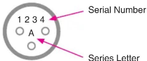
To register your product, you will need the serial number and series letter for each microphone.
You can locate this information between the pins of the XLR connector
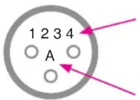
Serial Number
Series Letter
Congratulations on your purchase of the Earthworks DK7 DrumKit™ High Definition Multi-microphone Drum System. When compared to conventional drum mics, Earthworks mics will provide more detail in the attack, reproduce subtle low level details, near-perfect polar response, far less phase issues when close miking and nearly twice the amount of rear rejection. We welcome you into an entire new world of pristine drum sound using Earthworks High Definition Drum Microphones™.
Happy Drumming!
Please verify that you have received everything listed below.
Included with the DK7 DrumKit™ Drum Microphone System:
2 - SR25 Cardioid Microphones (overheads)
4 - DM20 DrumMic™ (toms & snare)
1 - SR20LS (kickdrum)
4 - RM1 RimMount™ (for DM20s)
3 - SRW3 Foam Windscreens (for SR25s & SR20LS)
4 – PW1 Windscreens (for DM20s)
1 – High Impact Carrying Case with custom foam insert
1 – User's Manual
Before You Start
When connecting the DK7 condenser microphones to a preamp with phantom power, allow up to one minute for the microphone to settle. Plugging in the microphone “hot” (phantom power already present at the input) will not damage the microphone, and is actually preferred for faster settling. It is normal for any phantom powered mic to “pop” when plugged in or powered up. Make sure to mute the signal to speakers and/or headphones when phantom power is first applied.
IMPORTANT NOTICE - Please Read This:
Drums, Microphone Output Level & Preamp Input Pads
The SR25, DM20 & SR20LS are designed for drum applications, and in most cases will not require the use of a pad to prevent overloading microphone pre-amps in mixers or consoles, computer audio interfaces and external preamps.
Different Types of Preamp Input Pads
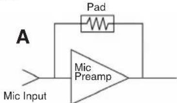
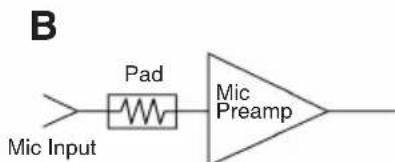
Some microphone preamps have a built-in pad that can be switched in or out which are not attenuators that precede the preamplifier input, but instead just reduce the gain of the preamplifier. These so-called pads will typically provide no preamp input overload protection from high level microphone signals (see Fig. 1-A). Other preamps have actual attenuators (pads) that precede the preamplifier input that will provide input overload protection (Fig. 1-B). Such pads typically provide 10dB or 20dB of attenuation. If your preamps have no pad prior to the preamp input, an external XLR type microphone pad can be used such as the Earthworks LP20 LevelPad™ that provides 20dB of attenuation when plugged into the microphone cable.
Figures 1-A & 1-B
Types of Preamp
Input Pads
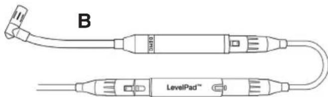
XLR mic pads can be inserted into the microphone cable in one of the three ways shown in Figures 2-A, 2-B and 2-C below:

Figures 2-A & 2-B XLR Mic Pad inserted at the microphone or in the mic cable
natural_image
Technical line drawing of a LevelPad device with labeled ports (no text or symbols beyond label)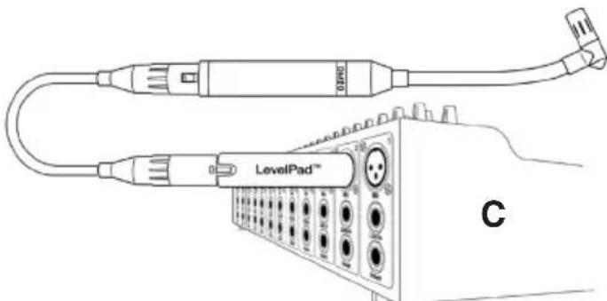
natural_image
Line drawing of a LevelPad device with connectors and ports (no text or symbols)Figure 2-C XLR Mic Pad inserted into mixer mic input
CAUTION: Plugging the LevelPad™ into the mic input of a mixer can cause damage to the mixer input connector if the LevelPad™ receives a hard push at the side. However, if you are careful, placing the LevelPad™ at the mixer mic input can provide greater accessibility for inserting or removing the LevelPad™.
Miking Drums
There are many ways to mic drums and most every recording or live sound engineer has their own way of doing this. Our objective is not to indicate which drum miking approach is better, but to make suggestions and look at advantages and disadvantages of each.
Multi-microphone Method
The objective of multi-microphone drum miking is to place a separate microphone on most or all the elements of the drum set. Typically, separate mics are used on snare, toms, hi-hat and kickdrum, along with one or two overhead microphones. The overhead mics pick up the overall sound of the drum set including cymbals (which are typically not miked separately). By this method, the mixing engineer can control the level, and signal processing (limiting, EQ, etc.) for each element of the drum set (toms, snare, hi-hat, etc.). For live sound, multi-miked drums are desirable by providing more control and more gain before acoustic feedback. When recording, multi-miking drums in a large room with high ambient sound reduces the amount of unwanted room sound and provides greater control of the drum mix.
Earthworks Near-Perfect Polar Response
One of Earthwork's proprietary technologies is near-perfect polar response i.e. very uniform frequency response over the front 160 degrees of the microphone. Conventional microphones (even expensive ones) have a loss of high frequencies at the sides of the microphone (Fig. 3-B). If you ever tried to put three singers on a single directional microphone you found that the singer at the front of the mic sounded great, but the two at the sides sounded muffled due to the lack of high frequency pickup at the sides of the mic. In contrast, the Earthworks proprietary polar technology provides virtually the same frequency response at the sides of the microphone as at the front (Fig. 3-A). In addition, this uniform frequency response at the front and sides of the microphone dramatically reduces phase cancellation issues when multi-miking drums.
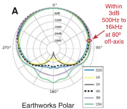
radar
| Frequency | Value Range | | --------- | ----------- | | Within 3dB 500Hz to 16kHz at 80° off-axis | Not labeled (red arrow) |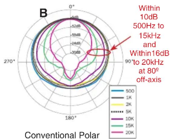
Figures 3-A & 3-B Earthworks vs. Conventional Polar Response
Nearly Twice the Amount of Rear Rejection
One “disadvantage” of the multi-microphone approach is picking up unwanted sound from other elements of the drum set at the rear of each microphone. Conventional microphones only provide about 18dB of rear rejection, while Earthworks microphones provide nearly twice that amount. Therefore, Earthworks drum mics will dramatically reduce leakage present at the rear of each microphone. Figures 4 and 5 illustrate this.
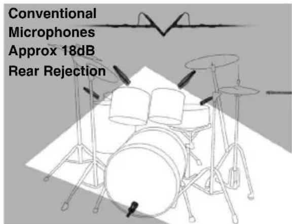
Figure 4 Rear Rejection of Conventional Drum Mics
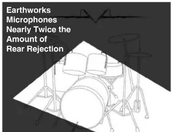
Figure 5 Rear Rejection of Earthworks Drum Mics
Inserting the DM20 Tom and Snare Microphone into the RM1 RimMount™
The RM1 RimMount is designed to allow the DM20 to be mounted on the side of a tom or snare in addition to miking either the top and/or bottom heads.
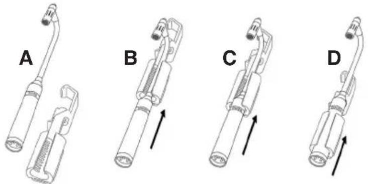
It is suggested that the DM20 microphone be inserted into the RimMount™ prior to attaching it to the drum. First insert the mic head and the gooseneck into the rubber holder from the bottom of the RimMount™ (Fig. 6-B). Then push on the body of the microphone from the bottom (XLR connector end) to move the microphone up inside the rubber holder (Figures 6-C & D). The fit will be firm, so apply a little pressure to move the microphone body up into the rubber mic holder.
Figures 6 A-D
Inserting the DM20
DrumMic™ into the
RM1 RimMount™
natural_image
Four technical illustrations of a medical or laboratory device with labeled parts (A, B, C, D), showing mechanical components and directional arrows indicating movement.Mounting the RimMount to the Drum
The RM1 is designed for “metal” drum rims, and will not work on wooden drum rims. Attaching the RimMount to the drum rim is quite easy. While reading this section, please refer to Figure 7-A (on the following page) that shows the various
elements of the RimMount™. First, loosen the thumbscrew so there is more than enough space for the Delrin® cushioned rim-guide to clear the bottom of the drum rim. Then determine where on the drum rim you want to put the microphone, then put the “hook portion” of the RimMount bracket in that place on the drum rim.
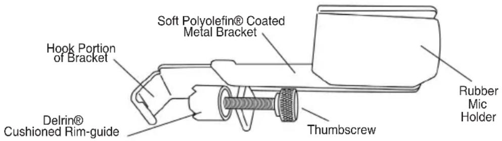
Figure 7-A. Elements of the RM1 RimMount ^TM
Notice that the Delrin® cushioned rim-guide has two sets of grooves. One groove is in the “center” of the rim-guide which should keep the RlmMount metal bracket parallel to the drum shell (#1 in Fig. 7-B below). The other groove is “off center” allowing the metal bracket of the RimMount to be placed closer or further from the drum shell (Fig. 7 #2 & #3). The object is to keep the metal bracket parallel to the drum shell so the microphone can be placed higher or lower in the rubber mic holder without the mic or its connector being obstructed by the drum shell.
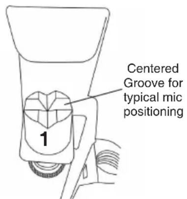
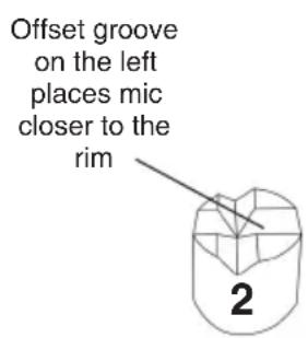
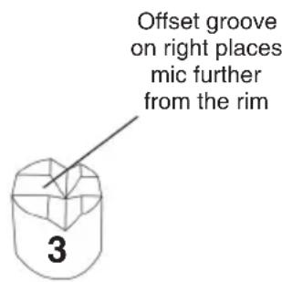
Figure 7-B Positioning the Cushioned Rim-guide
Adjusting the Microphone Height
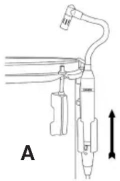
Once the RimMount™ is mounted securely and parallel to the drum rim, with the DM20 microphone housed in the rubber holder, the microphone body can be moved either up or down in the rubber holder for the desired height. Then the gooseneck will provide a significant amount of latitude in positioning the microphone head from any body height. Adjusting the height of the DM20 microphone body is indicated in Figures 8-A and 8-B on the following page.
Various types of metal drum rims have the bottom flange either closer to or further from the drum shell. One of the three positions (Fig. 7, 1, 2 or 3) will allow the RimMount™ bracket to be mounted parallel to the drum shell. Position the rim-guide so the bottom edge “flange” of the drum rim fits comfortably into one of the rim-guide grooves. This will ensure the cushioned rim-guide remains
in place as you tighten the thumbscrew to firmly secure it to the drum rim. The soft protective Polyolefin® coating on the RimMount™ metal bracket will prevent scratching the drum shell finish.
Figures 8-A and 8-B
Adjusting the DM20
Microphone Height
natural_image
Diagram of a medical or laboratory device with labeled parts and directional arrow (no readable text or symbols)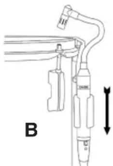
natural_image
Technical line drawing of a mechanical device with labeled part B and directional arrow (no text or symbols beyond label)Positioning the Microphone Head
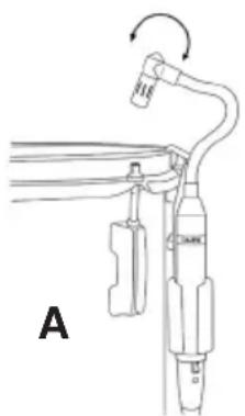
Once the DM20 microphone height has been set, then position the microphone head. It is suggested that the microphone head be placed between 1.5 to 3 inches above the drumhead. The flexible gooseneck will allow you to move the microphone head either up or down above the drumhead as well as in or out from the drum rim. You can also change the angle of the microphone head as shown in Figure 9-A. The microphone head can be aimed more toward the center of the drum head by changing the position of the gooseneck (Fig. 9-B). Keep in mind that the microphone head should never be placed “parallel” to the drumhead, but should always be at “an angle.” This will prevent the microphone diaphragm being forced against its backplate which could cause an unwanted pop or thump in the live sound or recording system.
Figures 9-A & 9-B
Positioning the
Microphone Head
natural_image
Diagram of a medical or laboratory procedure setup with labeled components and directional arrows (no readable text or symbols)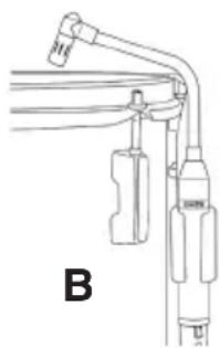
natural_image
Technical line drawing of a mechanical device with no visible text or symbolsHigh Acoustic Sound Levels of Close Miked Drums
When close miking drums, keep in mind that the acoustic sound level at the microphone head is extremely high. Microphones used for close miking drums should be able to handle at least 140dB SPL to prevent audible distortion. The DM20 DrumMic™ will handle up to 150dB SPL. With these high sound pressure levels, the DM20 microphone output level may be as much as +15dBV which may overload some microphone preamplifier inputs. To prevent this, switch in the mic pad on your preamp. If that doesn't work, then add an XLR mic pad such as the Earthworks LP20 LevelPad™ into the microphone cable that will provide 20dB of attenuation to help prevent any distortion or overload from the mic preamp. For full information refer to page 2 of this manual.
Close Miking Snare Drums with the DM20
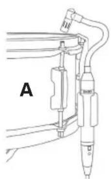
The DM20 has been optimized for miking toms and snare. With its frequency response of 50Hz to 20kHz it will provide a full and fat sound from your toms and a nice crisp sound from your snare. If you feel that there is too much low frequency response when miking a snare, use either a high-pass filter set somewhere between 60Hz and 100Hz or a low frequency equalizer (EQ) to attenuate (i.e. cut) a few dB in the area of 60Hz to 100Hz for the desired results. The DM20 can be used to mic either the top drumhead, bottom drumhead or both. Figure 10-A shows the DM20 placed over the top drumhead of a snare while Figure 10-B shows a snare drum with both the top and bottom heads miked.
natural_image
Technical line drawing of a mechanical device with labeled section A (no text or symbols beyond label)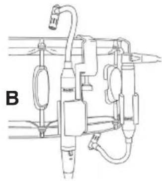
natural_image
Technical line drawing of a mechanical assembly with pipes and components (no text or symbols)Figures 10-A and 10-B Miking the Top or Top & Bottom of a Snare
Close Miking Toms with the DM20
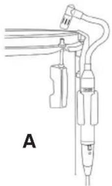
The extended low frequency response of the DM20 DrumMic™ will provide a rich and full tom sound. You can mike either the top and/or bottom head of a tom with the DM20 in a similar configuration as on snare as shown above in Figure 10-B. You will notice in Figure 11-A that the microphone head is placed closer to the drum rim, while in Figure 11-B the microphone head is aimed toward the center of the drum head by changing the position of the gooseneck. Experiment with the mic head placement as the sound or tone can change with the mic head in various positions.
Figures 11-A and 11-B
Miking the Head
of a Tom
natural_image
Technical line drawing of a medical or laboratory device with no visible text or symbols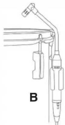
natural_image
Technical line drawing of a medical or laboratory device with labeled component B (no text or symbols on the device itself)Drum Overhead Microphone Placement
For overhead drum miking use the SR25s. The low frequency response (50Hz) of the SR25 will pick up less of the kickdrum and the lower frequencies from the toms. This will be a help during mixing by providing more control of the individual tom and kickdrum mics, rather than having too much low frequency information picked up by the overhead mics.
X/Y Stereo Overhead Miking
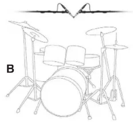
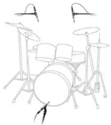
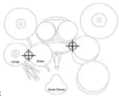
There are two basic ways to position overhead drum mics, either by placing the mics in an X/Y position (Figures 12-A & 12-B) or by separating the microphones by some predetermined distance (Figures 13-A and 13-B). The X/Y position will provide less of a stereo image than the separated microphone method.
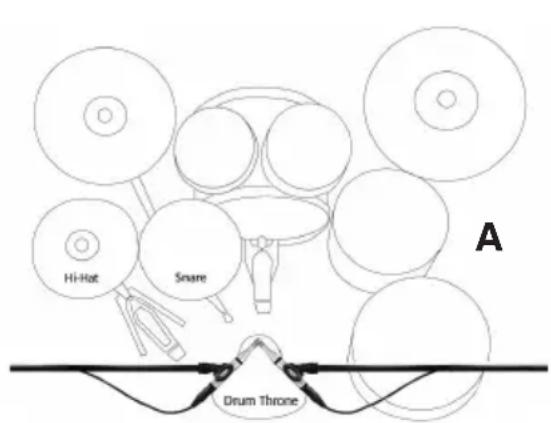
Figure 12-A Horizontal X/Y Positioning
natural_image
Line drawing of a drum with three pans and two drums, no text or symbols presentFigure 12-B Vertical X/Y Positioning
Figures 12-A and 12-B show two variations of X/Y microphone placement. The suggested microphone “height” should be approximately 2 feet above the drummer’s head. Moving the mics lower will provide more detail, while moving them higher will capture a wider overall image of the drum set in addition to more room sound. Both the horizontal and vertical X/Y positioning will provide excellent results in a drum booth or an acoustically treated small room as well as in a large room. If you are using a drum booth or a room with a low ceiling, the horizontal X/Y version shown in Figure 12-A may be more ideal, as it typically requires less height.
natural_image
Line drawing of a multi-part electric guitar with drum, pans, and speakers (no text or symbols)A Overhead miking front view
B
Overhead miking
aiming positions
top view
Figures 13-A and 13-B
Separated Overhead Miking
Separated Overhead Miking (Figures 13-A & B) allows the microphones to be placed further apart and they can also be positioned closer to the drum than when using X/Y positioning. Placing the overhead mics closer to certain elements of the drum set can reduce the ambient room sound while also picking up more subtle details of the drums. When using Earthworks High Definition Microphones as overheads, you can place the microphones closer to the drums without fear of hearing cymbal splash or splatter.
Miking the Hi-Hat
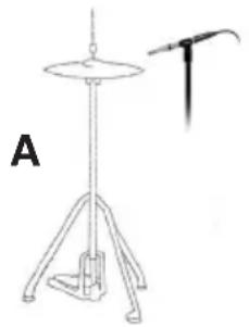
There are many approaches to miking a hi-hat. We suggest using an SR25 or DM20 placed approximately 2 inches above the top hi-hat cymbal (Fig. 14-A) in addition to placing the microphone approximately 2 to 3 inches from the edge of the hi-hat cymbals (Fig. 15). The mic can also placed under the hi-hat in relatively the same position (Fig. 14-B). However, if the microphone is placed close to where the two cymbals come together, the bursts of air generated when the two cymbals close may result in an undesirable thumping or popping sound from the microphone (Fig. 14-C).
natural_image
Line drawing of a stand with a curved handle and labeled point A (no text or symbols on the diagram itself)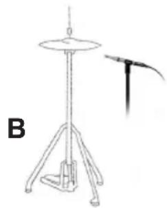
natural_image
Line drawing of a stand with a circular top and tripod base, next to a vertical tool or bracket (no text or symbols)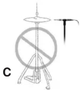
natural_image
Diagram of a prohibition sign with a circular symbol and a vertical pole, labeled 'C' (no text or symbols on the diagram itself)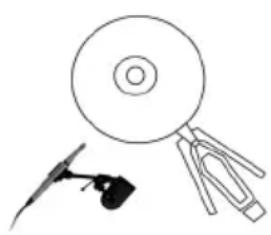
natural_image
Simple line drawing of a CD/DVD and a stylized object (no text or symbols)Figures 14-A, B & C Miking a Hi-hat (front view)
Figure 15 Miking a Hi-hat (top view)
Important: Using the SR20LS on Kickdrum
Initially you may not hear the fat low-end sound of mics designed specifically for kickdrum (i.e. kickdrum EQ built into the mic). Such mics typically do not sound good when miking most other instruments or vocals. In contrast, the SR20LS has a full frequency response from 20HZ to 20kHz and is an incredible kickdrum mic that can also be used for miking most anything else. The SR20LS has a lower frequency response than most kickdrum mics and will provide outstanding results on kickdrum, however you will need to EQ this mic for kickdrum (see pages 10 & 11).
Miking a Kickdrum with No Hole in the Front Head
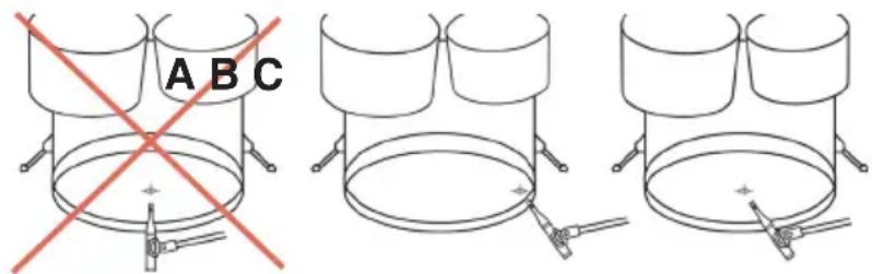
The Earthworks SR20LS microphone is designed for miking kickdrums and is a precision condenser microphone that is sensitive to large bursts of air. However, this microphone when positioned properly, they will produce an incredible kick-drum sound. For optimum results it is crucial to place the SR20LS at a 45 degree angle to the head (which reduces the air burst at the front of the microphone). Whether your kickdrum has a front head or not, place the SR20LS at a 45 degree angle to the front of the kickdrum as indicated in Figure 16-B or 16-C. Do not place the front of the microphone parallel to the drum head as shown in Figure 16-A. Field tests have shown that the best results by miking the drum just off of the rim as shown in Figure 16-B. The kickdrum head can also be miked at the center as shown in Figure 16-C. If there is any popping from the air bursts, place the enclosed windscreen on the mic and make sure it is placed at a 45 degree angle to the drum head.
Figures 16-A, B & C
Miking a Kickdrum
Miking a Kickdrum with a Hole in the Front Head
First, make sure the mic clip is attached all the way at the bottom (XLR end) of the microphone allowing it to go deeper inside the kickdrum (Figures 17-A & 17-B).

Figures 17-A & B Attach Mic Clip at XLR End of the Microphone
When miking the kickdrum at the hole in the head keep in mind that the highest velocity of air from the hole is closest to the outside or inside of the hole (Figures 18-A & 18-B) which could cause the microphone to pop.
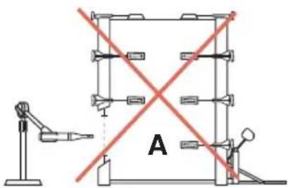
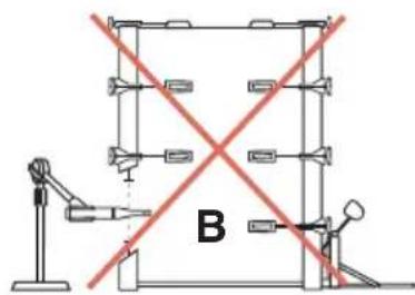
Figures 18-A & B High Air Velocity Close to Hole in Head
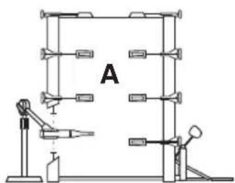
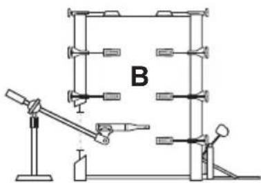
For optimum results place the microphone at least 6 inches inside the hole (Fig. 19-A) or closer to the beater head (Fig. 19-B). With the mic inside the kickdrum it should be placed at an angle (mic tip not parallel to the head). When using a taller mic stand with the boom at an angle you cannot get the mic as far inside the kickdrum as with a shorter mic stand and the boom parallel to the floor (Figures 19-A & 19-B).
natural_image
Technical diagram of a mechanical assembly with labeled component B, showing components mounted on a lever and base (no text or symbols beyond label)Figures 19-A & B Suggested Miking inside Kickdrum
EQ and Signal Processing
The SR20LS has a flat frequency response and in most cases you will need to EQ it for kickdrum. Standard practice is to boost the low frequency range to make a kick-drum sound fatter, and then boost the mid and/or high frequency range to hear more snap from the beater. However, you may need to rethink this approach when using the SR20LS with its extended low frequency and high frequency response compared to most other popular kickdrum mics. This extended response may reduce the amount of low and high frequency EQ that would typically be used when miking a kickdrum.
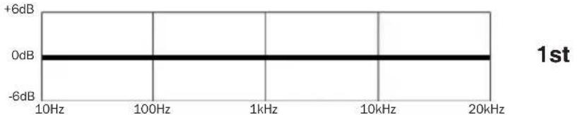
We suggest that you first listen with the EQ “flat” (Fig. 20), with all other signal processing turned “off.” You may be surprised how good this mic sounds all by itself. First, try moving the mic around, whether placed inside or outside of the kickdrum for the desired balance of beater sound and fat low frequency kickdrum sound.
Suggested procedure for EQ'ing a kickdrum when using the SR20LS
line
| Frequency | Value | | --------- | ----- | | 10Hz | 0dB | | 100Hz | 0dB | | 1kHz | 0dB | | 10kHz | 0dB | | 20kHz | 0dB |Figure 20 Start with EQ "Flat"
line
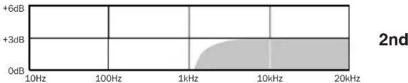
| Frequency | Value | | --------- | ----- | | 10Hz | +6dB | | 100Hz | +3dB | | 1kHz | 0dB | | 10kHz | +3dB | | 20kHz | +6dB |Figure 21 Add Shelving EQ in High Frequency Range
line
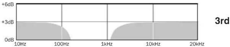
| Frequency | Value | | --------- | ----- | | 10Hz | +6dB | | 100Hz | +3dB | | 1kHz | 0dB | | 10kHz | +3dB | | 20kHz | +6dB |Figure 22 Add Shelving EQ in Low Frequency Range
If you are still not pleased, first add a moderate amount of high frequency “shelving” EQ in the 2kHz to 3kHz range (Fig. 21) for the beater sound. Then if necessary, add a moderate amount of low frequency “shelving” EQ in the 60Hz to 80Hz range to fatten the low frequency sound (Fig. 22). Continue to play with the amount of EQ until you get the sound you want as all kickdrums are different. It is also standard practice to sometimes use compression, limiting and/or gates (expanders) for kickdrum. It is suggested that you first obtain the EQ’d kickdrum sound you want, then add compression, limiting and/or gating until you obtain the desired kickdrum sound. Many engineers using the SR20LS for kickdrum say it is the best kickdrum mic they have ever used. We hope you will find this to be your favorite kickdrum mic as well.
EARTHWORKS WARRANTY
All Earthworks® products carry a limited warranty (parts and labor). Please register your warranty at www.earthworksaudio.com/register If you have any problems with your Earthworks products, please contact our warranty/repair department by email at returns@earthworksaudio.com or by telephone at (603) 654-2433, ext 119.
NOTES:
Inside Rear Cover
EARTHWORKS WARRANTY
Please Remember to Register
Your Microphone(s) for Warranty at:
www.earthworksaudio.com/register
All Earthworks ^® products carry a limited warranty (parts and labor).
To register your product, you will need the serial number and series letter for each microphone.
You can locate this information between the pins of the XLR connector
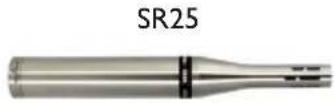
SR25 Cardioid for Overheads, High Hat
| Frequency response | 20Hz to 25kHz | |
| Polar Pattern | Cardioid | |
| Sensitivity | 10mV/Pa (-40dBV/Pa) | |
| Power requirements | 24-48V Phantom @ 10mA | |
| Peak acoustic input | 150dB SPL | |
| Signal-to-Noise Ratio | 74dB A-weighted | |
| Output | XLR (PIN 2+) | |
| Output Impedance | 200Ω bal. (between pins 2& 3 ) | |
| Minimum output load | 600Ω, balanced between pins 2&3 | |
| Noise | 20dB SPL (A-weighted) | |
| Dimensions L & D | Length 6.5 inches (165mm) Diameter .860 inches (22mm) | |
| Weight | .35lb (160g) | |
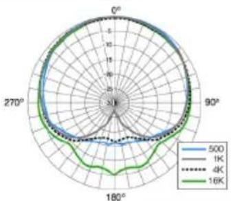
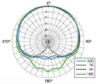 | SR25 Polar Response | |
DM20 DrumMic™ for Toms & Snare
| Frequency response | 20Hz to 20kHz |
| Polar Pattern | Cardioid |
| Sensitivity | 8mV/Pa (-42dBV/Pa) |
| Power requirements | 24-48V Phantom @ 10mA |
| Peak acoustic input | 150dB SPL |
| Signal-to-Noise Ratio | 74dB A-weighted |
| Output | XLR (PIN 2+) |
| Output Impedance | 200Ω bal. (between pins 2&3) |
| Minimum output load | 1,000Ω, balanced between pins 2&3 |
| Noise | 20dB SPL (A-weighted) |
| Dimensions L & D | 11.12 inches (282.44mm).860 inches (22mm) |
| Gooseneck L & D | Length 4.75 inches (120.65mm)Diameter .375 inches (9.53mm) |
| Weight | .55lb (.25kg) |
 | |
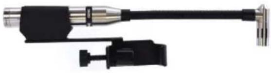
DM20 with RMI Rim Mount
natural_image
Close-up of a black cable connector with metallic connectors and a separate black connector (no text or symbols visible)SR20LS

SR20LS Cardioid for Kickdrum
| Frequency response | 20Hz to 20kHz |
| Polar Pattern | Cardioid |
| Sensitivity | 8mV/Pa (-42dBV/Pa) |
| Power requirements | 24-48V Phantom @ 10mA |
| Peak acoustic input | 150dB SPL |
| Signal-to-Noise Ratio | 74dB A-weighted |
| Output | XLR (PIN 2+) |
| Output Impedance | 200Ω bal. (between pins 2& 3 ) |
| Minimum output load | 1,000Ω, balanced between pins 2&3 |
| Noise | 20dB SPL (A-weighted) |
| Dimensions L & D | Length 7.57 inches (192.2mm) Diameter .860 inches (21.8mm) |
| Weight | .36lb (164g) |
radar
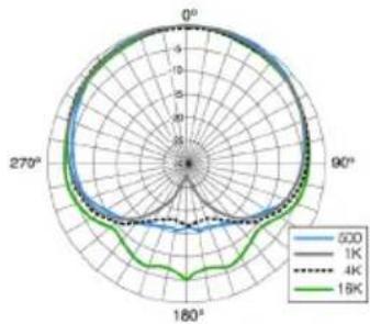
| Angle | 500 | 1K | 4K | 18K | |---|---|---|---|---| | 0° | 5.0 | 5.0 | 5.0 | 5.0 | | 90° | 5.0 | 5.0 | 5.0 | 5.0 | | 180° | 5.0 | 5.0 | 5.0 | 5.0 | | 270° | 5.0 | 5.0 | 5.0 | 5.0 |SR20LS Polar Response

Made in U.S.A.
Earthworks, Inc. 37 Wilton Rd. Milford, NH 03055 603-654-2433 email: sales@earthworksaudio.com
www.earthworksaudio.com Printed in U.S.A.
- Inside Front Cover
- EARTHWORKS WARRANTY
- Please Remember to Register
- Your Microphone(s) for Warranty at:
- www.earthworksaudio.com/register
- Please verify that you have received everything listed below.
- Included with the DK7 DrumKit™ Drum Microphone System:
- Before You Start
- IMPORTANT NOTICE - Please Read This:
- Drums, Microphone Output Level & Preamp Input Pads
- Different Types of Preamp Input Pads
- Miking Drums
- Multi-microphone Method
- Earthworks Near-Perfect Polar Response
- Nearly Twice the Amount of Rear Rejection
- Inserting the DM20 Tom and Snare Microphone into the RM1 RimMount™
- Mounting the RimMount to the Drum
- Adjusting the Microphone Height
- Positioning the Microphone Head
- High Acoustic Sound Levels of Close Miked Drums
- Close Miking Snare Drums with the DM20
- Close Miking Toms with the DM20
- Drum Overhead Microphone Placement
- X/Y Stereo Overhead Miking
- Separated Overhead Miking
- Miking the Hi-Hat
- Important: Using the SR20LS on Kickdrum
- Miking a Kickdrum with No Hole in the Front Head
- Miking a Kickdrum with a Hole in the Front Head
- EQ and Signal Processing
- Inside Rear Cover
Brand : Earthworks
Model : DK7
Category : Microphone