
PY1708 - Sensor IFM - Free user manual and instructions
Find the device manual for free PY1708 IFM in PDF.


| Product Type | Photoelectric Sensor |
| Model | PY1708 |
| Brand | IFM |
| Dimensions | M18 x 1 threaded barrel, length 65 mm |
| Weight | Approx. 50 g |
| Housing Material | Stainless steel (V4A) / Plastic (PBT) |
| IP Rating | IP67 |
| Power Supply | 10-30 V DC |
| Current Consumption | < 30 mA |
| Output Type | PNP / NPN, NO / NC programmable |
| Sensing Range | 0-2 m (depending on object and reflector) |
| Light Source | Red LED, 660 nm |
| Switching Frequency | 500 Hz |
| Protection | Reverse polarity, short circuit, overcurrent |
| Operating Temperature | -25 to 60 °C |
| Maintenance & Cleaning | Clean optical surfaces with a soft, lint-free cloth and mild detergent if needed. Do not use abrasive cleaners. |
| Safety | Disconnect power before installation or maintenance. Ensure proper electrical connection according to local regulations. |
| Spare Parts & Repairability | No user-serviceable parts. Contact IFM service for repair or replacement. |
| General Information | CE, RoHS compliant. Suitable for industrial automation applications. |
Frequently Asked Questions - PY1708 IFM
User questions about PY1708 IFM
0 question about this device. Answer the ones you know or ask your own.
Ask a new question about this device
Download the instructions for your Sensor in PDF format for free! Find your manual PY1708 - IFM and take your electronic device back in hand. On this page are published all the documents necessary for the use of your device. PY1708 by IFM.
USER MANUAL PY1708 IFM
Operating instructions Electronic pressure sensor
PY1708
UK
80289616 / 00 10 / 2019
natural_image
Technical line drawing of a cylindrical mechanical device with a valve and housing (no text or symbols)Contents
1 Preliminary note....3
1.1 Symbols used .... 3
2 Safety instructions ....3
3 Functions and features .... 4
3.1 Applications ....4
4 Function....5
4.1 Set-up via IO-Link 5
4.2 Scalable measuring range....5
4.3 Process data via IO-Link 5
4.4 Defined state in case of a fault 5
4.5 Operating modes 5
4.5.1 2-wire operation....6
4.5.2 3-wire operation....6
4.6 Analogue function 6
4.7 IO-Link 7
5 Installation....8
6 Electrical connection....9
7 Parameter setting .... 10
7.1 Parameter setting via PC....10
7.2 Parameter setting via the memory plug....10
7.3 Teach offset with the teach button 11
7.3.1 Scale analogue value 12
7.3.2 Select the standard unit of measurement (option)....12
7.4 User settings (optional)....12
7.4.1 Set damping for the analogue output 12
7.4.2 Set damping for the switching signal....12
7.4.3 Zero-point calibration....12
7.5 List of the parameters....13
7.6 Diagnostic functions 13
7.6.1 Read min/max values system pressure....13
8 Operation....13
9 Factory setting 14
1 Preliminary note
1.1 Symbols used
▶ Instruction
Reaction, result
[...] Designation of keys, buttons or indications
→ Cross-reference

Important note
Non-compliance may result in malfunction or interference.

Information
Supplementary note

2 Safety instructions
- The device described is a subcomponent for integration into a system.
- The manufacturer is responsible for the safety of the system.
- The system manufacturer undertakes to perform a risk assessment and to create a documentation in accordance with legal and normative requirements to be provided to the operator and user of the system. This documentation must contain all necessary information and safety instructions for the operator, the user and, if applicable, for any service personnel authorised by the manufacturer of the system.
- Read this document before setting up the product and keep it during the entire service life.
- The product must be suitable for the corresponding applications and environmental conditions without any restrictions.
- Only use the product for its intended purpose (→ Functions and features).
- Only use the product for permissible media (→ Technical data).
- If the operating instructions or the technical data are not adhered to, personal injury and/or damage to property may occur.
- The manufacturer assumes no liability or warranty for any consequences caused by tampering with the product or incorrect use by the operator.
- Installation, electrical connection, set-up, operation and maintenance of the product must be carried out by qualified personnel authorised by the machine operator.
- Protect units and cables against damage.
3 Functions and features
The device monitors the system pressure of machines and installations.
2 outputs are available:
- OUT1: Measured pressure value via IO-Link.
More information → 4.7 and → 7.
- OUT2: Analogue signal proportional to pressure 4...20 mA
3.1 Applications
Type of pressure: relative pressure
| Order number | Measuring range | Pressure rating (max. permissible pressure) *) | Bursting pressure | |||
| Pressure sensors with G1 Aseptoflex Vario | ||||||
| mbar psi | mbar psi bar psi | |||||
| PY1708 | -12.5...250 | -0.182...3.626 | 6000 | 87 | 30 | 435 |
| *) With static overload pressure. | ||||||
| MPa = (measured value in bar) ÷ 10 kPa = (measured value in bar) x 100 | ||||||

Avoid static and dynamic overpressure exceeding the indicated pressure rating by taking appropriate measures.
The indicated bursting pressure must not be exceeded.
Even if the bursting pressure is exceeded only for a short time, the unit may be destroyed.
ATTENTION: Risk of injury!

The units are vacuum resistant.
4 Function
The unit converts the system pressure into an analogue output signal (4...20 mA). Moreover, it provides the process data via IO-Link.
4.1 Set-up via IO-Link
The device parameters can be set via IO-Link:
- The device parameters are set via the IO-Link interface ( 4.7 and 7).
- All settings can also be carried out before installation of the unit.
4.2 Scalable measuring range
The measuring range can be scaled to up to 20% of the final value of the measuring range:
- Setting the parameter [ASP2] defines at which measured value the output signal is 4 mA.
- Setting the parameter [AEP2] defines at which measured value the output signal is 20mA.
4.3 Process data via IO-Link
All process data is available via IO-Link:
- The unit is designed for fully bidirectional communication.
- The following options are available:
- Remote display: reading and display of the current system pressure.
- Remote parameter setting: reading and changing the current parameters via IO-Link parameter setting ( 4.7).
4.4 Defined state in case of a fault
- If a fault is detected, the analogue output passes into a defined state (= 21.5mA) .

In case of a fault indication (= 21.5 mA)
▶ Read parameters via IO-Link or contact the manufacturer
4.5 Operating modes
The operating mode is defined by the wiring ( 6 Electrical connection) and automatically recognised by the unit.
4.5.1 2-wire operation
| OUT2 (pin 2) | Analogue signal proportional to pressure 4...20 mA |
4.5.2 3-wire operation
| OUT1 (pin 4) | Communication via IO-Link |
| OUT2 (pin 2) | Analogue signal proportional to pressure 4...20 mA |
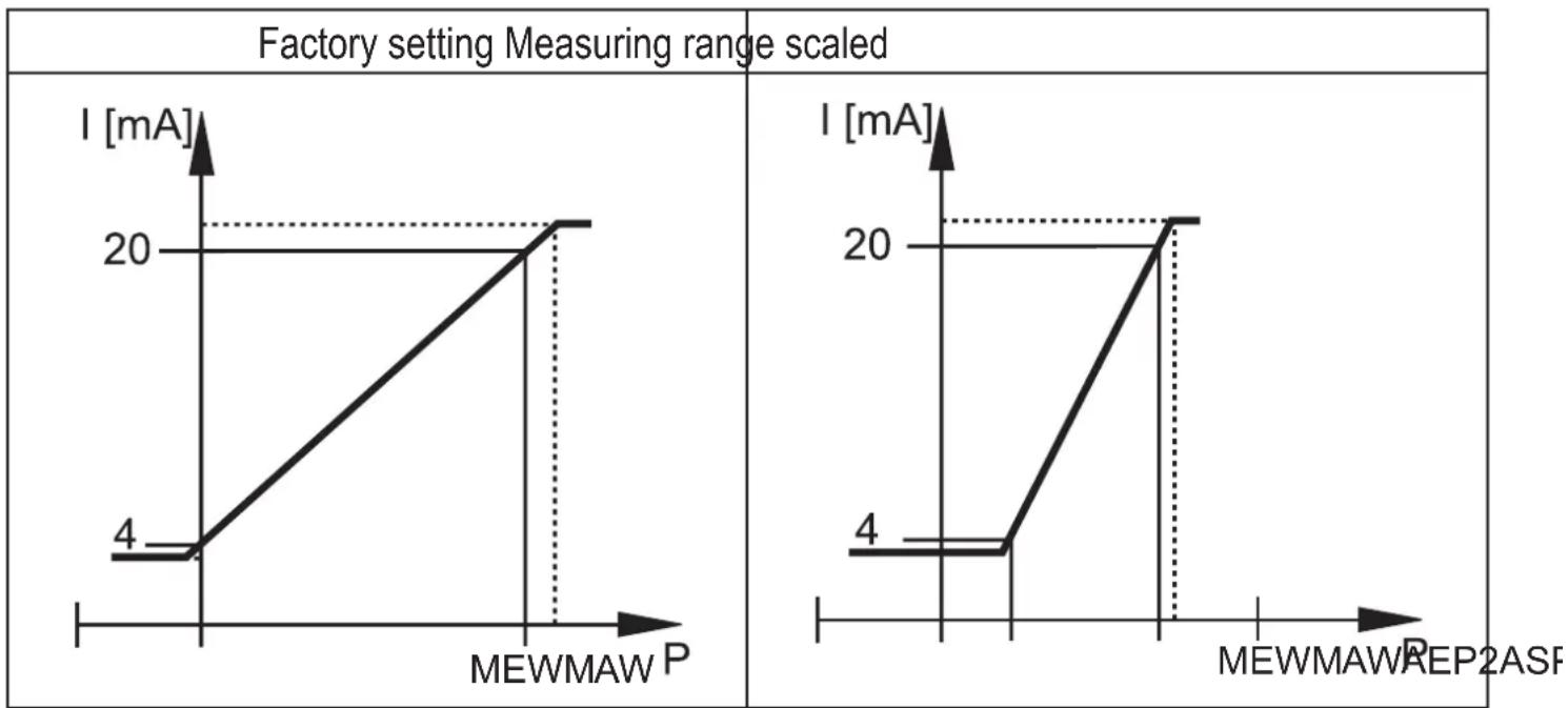
4.6 Analogue function
OUT2 is an analogue output:
Minimum distance between [ASP2] and [AEP2] = 20 % of the measuring span.
line
| MEWMAW P | I [mA] | | -------- | ------ | | 0 | 4 | | 1 | 20 | | 2 | 20 | | 3 | 4 | | 4 | 4 |P = System pressure
MAW = Initial value of the measuring range
ASP2 Analogue start point [ASP2]
MEW = Final value of the measuring range
AEP2 = Analogue end point [AEP2]
In the set measuring range, the output signal range is between 4 and 20 mA.
It is also indicated:
• System pressure above [AEP2]: 20...20.5 mA
- System pressure below [ASP2]: 4...3.8 mA
- Fault indication according to Namur: 21.5 mA
4.7 IO-Link
The device has an IO-Link communication interface which requires an IO-Link-capable module (IO-Link master).
The IO-Link interface enables direct access to the process and diagnostic data and provides the possibility to set the parameters of the unit during operation.
In addition, communication is possible via a point-to-point connection with a USB adapter cable.
The IODDs necessary for the configuration of the unit, detailed information about process data structure, diagnostic information, parameter addresses and the necessary information about the required IO-Link hardware and software can be found at www.ifm.com.

5 Installation

Before installing and removing the unit: Make sure that no pressure is applied to the system.

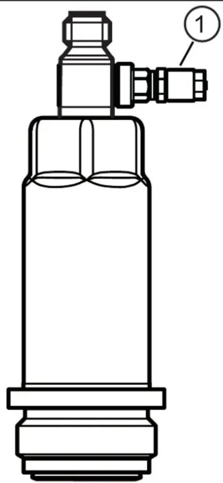
During sensor installation, do not exert any axial leverage with the screw-in tool on the rotatable tube adapter (1) ( fig. 1).
natural_image
Technical line drawing of a mechanical device with no visible text or symbolsFig. 1
1: Tube adapter
▶ Insert the unit in a process connection.
▶ Tighten firmly. Recommended tightening torque: 35 Nm Depends on the sealing type, the pressure load and the lubrication!
▶ Attach the tube onto the tube adapter (1) and place the free end in a protected area.

A zero-point calibration of the measured value is possible via the teach function ( 7.3 Teach offset with the teach button)
6 Electrical connection

The unit must be connected by a qualified electrician.
The national and international regulations for the installation of electrical equipment must be adhered to.
Voltage supply according to EN 50178, SELV, PELV.
▶ Disconnect power.
▶ Connect the unit as follows:
| Core colours | 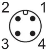 | 2-wire operation (2L)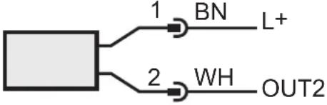 | ||
| 1 BN brown | ||||
| 2 VH white | ||||
| 3 BU blue | ||||
| 4 BK black | ||||
3-wire operation (3L)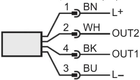 | ||||
| OUT1: communication via IO-LinkOUT2: analogue outputColours to DIN EN 60947-5-2 | ||||
| Wiring example | ||||
| (2-wire) 1 x analogue (3-wire) 1 x analogue | ||||
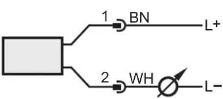 | 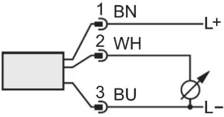 | |||
| (3-wire) 1 x analogue / 1 x IO-Link (3-wire) 1 x IO-Link | ||||
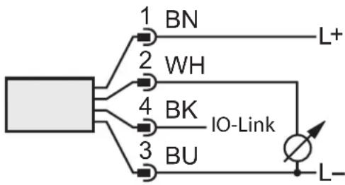 | 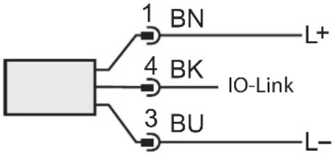 | |||

7 Parameter setting

The unit can be configured via the IO-Link function.
▶ Prepare IO-Link hardware and software for parameter setting.
▶ Connect the unit with e.g. an IO-Link interface ( 7.1) or a programmed memory plug ( 7.2).
▶ Set the parameters.
▶ Put the unit into operation.
The parameters can be set before installation or during operation.

Changing parameters during operation can influence the function of the plant.
▶ Ensure that there will be no malfunctions in your plant.
7.1 Parameter setting via PC
For parameter setting, an IO-Link-capable software is necessary (e.g. LINERECORDER DEVICE).
IO-Link interfaces from ifm are available for the connection of the unit via the USB interface of a computer → www.ifm.com.
▶ Prepare computer, software and interface.
▶ Connect the unit with the IO-Link interface.
▶ Follow the menu of the IO-Link software.
▶ Set the parameters.
▶ Put the unit into operation.
Adjustable parameters ( 7.5)
7.2 Parameter setting via the memory plug
A parameter set can be written to the unit / can be recorded by the unit via a memory plug (ifm storage module) → www.ifm.com.

In order to allow for data to be written from the memory plug to the sensor, the sensor must have the factory setting.

If the sensor has been configured, the memory plug records the parameter set which can then be transferred to other sensors of the same type.
▶ Load a suitable parameter set (e.g. from a PC or from a sensor of the same type) to the memory plug.
▶ Connect the memory plug between sensor and socket.
Sensor with factory setting:
When voltage is supplied, the parameter set is transferred from the memory plug to the sensor.
Sensor with changed settings:
When voltage is supplied, the memory plug records the sensor's parameter set.
▶ Remove the memory plug.
▶ Put the unit into operation.
Adjustable parameters ( 7.5)
You can find more information about the memory plug in the corresponding technical documentation → www.ifm.com.
7.3 Teach offset with the teach button
An external teach button (E30425) allows for a zero-point calibration (calibration offset). The current measured value is taken as internal zero point if it lies within a range of +/- 3% of the final value of the measuring range.

For connection information see data sheet of E30425
If a teach button is connected, no IO-Link communication is possible
▶ Integrate the teach button between the installed sensor and the supply cable.
▶ Maintain the plant pressure constantly at zero (configurable range = +/- 3% of the measuring span).
▶ Press the button for > 2 ... < 10 s.
When voltage is supplied, the LED in the button flashes at 2 Hz and configures the zero point (calibration offset).
In case of a fault, the LED flashes at 8 Hz.

7.3.1 Scale analogue value
| ▶ Select [ASP2] and set the value at which 4 mA is provided.▶ Select [AEP2] and set the value at which 20 mA is provided. Minimum distance between ASP2 and AEP2 = 20 % of the measuring span (scaling factor 5). | [ASP2][AEP2] |
7.3.2 Select the standard unit of measurement (option)
| ▶ Select [uni] and set the unit of measurement:[mbAr] / [kPA] / [PSI] / [mmWS] / [inH2O] | [uni] |
7.4 User settings (optional)
7.4.1 Set damping for the analogue output
| ▶ Select [dAA] and set the damping constant (rise time 10...90 %) in seconds; setting range 0.000...4.000 s. | [dAA] | |
 | Damping [dAA] only influences the analogue output / analogue signal path. | |
7.4.2 Set damping for the switching signal
| ▶ Select [dAP] and set the damping constant in seconds (T value: 63 %); setting range 0.000...4.000 s. | [dAP] | |
 | The damping [dAP] influences the process data flow (IO-Link communication). | |
7.4.3 Zero-point calibration
| ▶ Select[tcof]Compared to the real measured value, the internal measured value (operating value of the sensor) is shifted.• Teach range: -3...+3 % of the measuring span | [tcof] |
7.5 List of the parameters
| Parameter Function | |
| ASP2 | Analogue start pointMeasured value at which 4 mA is provided. |
| AEP2 | Analogue end pointMeasured value at which 20 mA is provided.Minimum distance between ASP and AEP = 20 % of the measuring span. |
| Lo Minimum value memory for system pressure. | |
| Hi Maximum value memory for system pressure. | |
| tcoF | Zero-point calibration (calibration offset)Compared to the real measured value, the internal measured value (operating value of the sensor) is shifted.• Teach range: - 3...+ 3 % of the measuring span. |
| dAA | Damping for analogue outputPressure peaks of short duration or high frequency can be filtered out using this function. |
| dAP Damping of the process value (only applies to IO-Link evaluation). | |
| uni Standard unit of measurement for system pressure. | |
7.6 Diagnostic functions
7.6.1 Read min/max values system pressure
| ▶ Select [Hi] or [Lo] to display the highest or lowest measured process value:- [Hi] = maximum value system pressure- [Lo] = minimum value system pressureThe memory can be reset. | [Hi][Lo] |
8 Operation
After power on, the unit is in the Run mode (= normal operating mode). It carries out its measurement and evaluation functions and provides output signals according to the set parameters.
9 Factory setting
| Factory setting User setting | |
| ASP2 0% VMR* | |
| AEP2 100% VMR * | |
| uni mbAr | |
| tcoF 0.0 | |
| dAA 0.1 | |
| dAP 0.06 |
(VMR) final value of the measuring range
* = The specified per cent value of the final value of the measuring range (VMR) is set
Further technical data

Further technical data and scale drawing at www.ifm.com.
UK
More information at www.ifm.com
- Contents
- Preliminary note
- Symbols used
- Safety instructions
- Functions and features
- Applications
- Function
- Set-up via IO-Link
- Scalable measuring range
- Process data via IO-Link
- Defined state in case of a fault
- Operating modes
- 2-wire operation
- 3-wire operation
- Analogue function
- IO-Link
- Installation
- Electrical connection
- Parameter setting
- Parameter setting via PC
- Parameter setting via the memory plug
- Teach offset with the teach button
- Scale analogue value
- Select the standard unit of measurement (option)
- User settings (optional)
- Set damping for the analogue output
- Set damping for the switching signal
- Zero-point calibration
- List of the parameters
- Diagnostic functions
- Read min/max values system pressure
- Operation
- Factory setting
- Further technical data
Brand : IFM
Model : PY1708
Category : Sensor