
GK-KIT-BG3 - Musical accessory ROLAND - Free user manual and instructions
Find the device manual for free GK-KIT-BG3 ROLAND in PDF.


| Product Type | GK Pickup Kit for Guitar |
| Brand | Roland |
| Model | GK-KIT-BG3 |
| Compatibility | Roland GK-compatible guitar synthesizers and converters (e.g., GR-55, GI-20) |
| Pickup Type | Hexaphonic (divided) magnetic pickup |
| Output Connector | 13-pin DIN |
| Installation | Fits standard magnetic pickup routes (Strat, Tele, etc.) |
| Number of Strings | 6 |
| Material | Plastic & metal components |
| Dimensions (each pickup) | Approx. 100 x 40 x 15 mm |
| Weight | Approx. 200 g |
| Power | Passive (no battery required) |
| Functions | Converts string vibrations into individual signals for polyphonic pitch-to-MIDI and synth control |
| Maintenance | Clean with a soft, dry cloth; avoid solvents |
| Safety | Avoid extreme temperatures and moisture |
| Spare Parts & Repairability | Serviceable by Roland authorized technicians; replacement parts available through Roland service centers |
| Included Items | Mounting screws, connection cable, installation guide |
| Color | Black |
Frequently Asked Questions - GK-KIT-BG3 ROLAND
User questions about GK-KIT-BG3 ROLAND
0 question about this device. Answer the ones you know or ask your own.
Ask a new question about this device
Download the instructions for your Musical accessory in PDF format for free! Find your manual GK-KIT-BG3 - ROLAND and take your electronic device back in hand. On this page are published all the documents necessary for the use of your device. GK-KIT-BG3 by ROLAND.
USER MANUAL GK-KIT-BG3 ROLAND
USING THE UNIT SAFELY
INSTRUCTIONS FOR THE PREVENTION OF FIRE, ELECTRIC SHOCK, OR INJURY TO PERSONS
About ⚠ WARNING and ⚠ CAUTION Notices
| WARNING | Used for instructions intended to alert the user to the risk of death or severe injury should the unit be used improperly. |
| CAUTION | Used for instructions intended to alert the user to the risk of injury or material damage should the unit be used improperly.Material damage refers to damage or other adverse effects caused with respect to the home and all its furnishings, as well to domestic animals or pets. |
About the Symbols
| △ | The △ symbol alerts the user to important instructions or warnings. The specific meaning of the symbol is determined by the design contained within the triangle. In the case of the symbol at left, it is used for general cautions, warnings, or alerts to danger. |
| ⊗ | The ⊗ symbol alerts the user to items that must never be carried out (are forbidden). The specific thing that must not be done is indicated by the design contained within the circle. In the case of the symbol at left, it means that the unit must never be disassembled. |
| ● | The ● symbol alerts the user to things that must be carried out. The specific thing that must be done is indicated by the design contained within the circle. In the case of the symbol at left, it means that the power-cord plug must be unplugged from the outlet. |
ALWAYS OBSERVE THE FOLLOWING
WARNING
- Before using this unit, make sure to read the instructions below, and the Owner's Manual.
- Do not open or perform any internal modifications on the unit.
- Do not attempt to repair the unit, or replace parts within it (except when this manual provides specific instructions directing you to do so). Refer all servicing to your retailer, the nearest Roland Service Center, or an authorized Roland distributor.
- Never use or store the unit in places that are: - Subject to temperature extremes (e.g., direct sunlight in an enclosed vehicle, near a heating duct, on top of heat-generating equipment); or are
- Damp (e.g., baths, washrooms, on wet floors); or are
- Humid; or are
- Exposed to rain: or are
• Dusty: or are
- Subject to high levels of vibration.
- Do not allow any objects (e.g., flammable material, coins, pins); or liquids of any kind (water, soft drinks, etc.) to penetrate the unit


WARNING
- Immediately turn the power off, and request servicing by your retailer, the nearest Roland Service Center, or an authorized Roland distributor, when:
- Objects have fallen into, or liquid has
been spilled onto the unit; or
• The unit has been exposed to rain (or
otherwise has become wet); or - The unit does not appear to operate normally or exhibits a marked change in performance.
- In households with small children, an adult should provide supervision until the child is capable of following all the rules essential for the safe operation of the unit.
- Protect the unit from strong impact. (Do not drop it!)


CAUTION
- Should you remove screws or springs, make sure to put them in a safe place out of children's reach, so there is no chance of them being swallowed accidentally.
Copyright © 2002 ROLAND CORPORATION
All rights reserved. No part of this publication may be reproduced in any form without the written permission of ROLAND CORPORATION.


This product complies with the requirements of European Directives EMC 89/206-EEC and LVD 73/23-EEC.
- For EU Countries

N225
Supplied parts contents
- Divided Pickup ....1 - Amp Board ....1 - GK Connector Board ....1 - Plate ....1 - Screw ....2
- Screen (for installing the Divided Pickup) ...2 - Spring (for installing the Divided Pickup) ...2
Wirings
■ For GK Connector-A 7-pin ...1
- For GK Connector-B S-pin ...
• For UK Volume 3-pin ...
- For Base-Signal 2-put ...1 - For Switch LED ... (pin)
- Ph 50% (1+1) 6-24h ...
- GK Volume (50 kΩ ± 20 % B curve) ....1 - LED ....1
• DOWN/S1, UP/S2 Switch
(ramentary type switch, push: ON) .....2
- GK/MIX/BASS Select Switch /Lands ON OFF ON Panels
(1) pml OK-OFF-A N high switch • Nut for CK Volume:
- Washer (for GK Volume)
Parts should be arranged separately
- Screw ... 4 - Ground Wire ... 3 (*1)
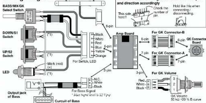
Wiring Diagram
Dimensional Drawing of the Hole
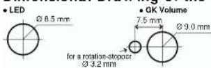
le (if necessary, a hole for a rotation-slopper can be drilled.)
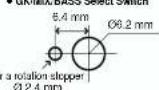
• GK-MIX'BASS Select Switch
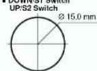
- DOWN/S1 Switch
Installation Notes
GK Connector Board
- Attach the connector to the plate with the supplied screws.
- Attach the plate to the bass with the screws. * Mount GK Connector board so that small connection port should place top surround bass surface.

For Bass Signal Wiring
- Do not exceed 12 Vp-p for input signal level.
- Solder uncovered wire (silver) to the earth (ground) of the bass.
- Solder the white wire to the bass signals.

About Transcription for Each Controller
When you transcribe each controller into bass itself or owner's manual, please transcribe as below:
GK Volume
DOWN/S Switch
UP/S2Switch
GK VOL
...DOWN/
UP/S2
For GK Volume Wiring
- Solder each signal wire of GK volume wiring with
volume 50 kU +20 % B curve
For Switch, LED Wiring
(Select Switch, DOWN/S1 Switch, UP/S2 Switch, LED)
- Ground wire (or each wire is common)
Do wiring as "Wiring Diagram (1)."
* Do not take power source from this circuit except for I.D.
- Using a toggle switch of 1 pole ON-OFF-ON momentary
for DOWN/S1, UP/S2, mounting can be simpler.
Black Connect ground 4: Blue DOWN/S 5: Yellow UP/S2
* In case of above, it is not possible to use simultaneous pressure for DOWN/S1 and DOWN/S2 strokes.
GK-KIT-BG
DIVIDED PICKUP KIT
Roland®
Owner's Manual
Thank you for purchasing the Roland GK-KIT-BG, a divided pickup kit. The GK-KIT-BG is a specialized kit for internal installation of the included bass divided pickup. Installing the components in the bass allows the bass to be used with GK-compatible devices for bass.
Before using this unit, carefully read the sections entitled: "USING THE UNIT SAFELY" and "IMPORTANT NOTES." These sections provide important information concerning the proper operation of the unit. To ensure proper installation – which is critical – and operation, please read this owner's manual carefully. The Owner's manual should be saved and kept on hand as a convenient reference.
IMPORTANT NOTES
In addition to the items listed under "USING THE UNIT SAFELY," please read and observe the following:
Roland assumes no liability concerning any damage to the bass and GK-KIT-BG upon installing the GK-KIT-BG. Please proceed with the installation using cation and care at your own risk.
Never use benzine, thinners, alcohol or solvents of any kind, to avoid the possibility of discoloration and/or deformation.
Use a reasonable amount of care when using the unit's buttons, sliders, or other controls; and when using its jacks and connectors. Rough handling can lead to malfunctions.
To avoid the risk of damage to internal components that can be caused by static electricity, please be careful whenever you handle or store the board.
To properly drive the GK-compatible device for bass with the CK-KIT-BC, you must adjust the height of the Divided Pickup and the sensitivity of the CK-compatible device for bass. Be sure to make these adjustments correctly, in accordance with this manual and the owner's manual for the GK-compatible device for bass.
Be sure to use the special cable supplied by us to connect the GK-KIT-BG to the GK-compatible device for bass. Use of any other cable may cause unnecessary problems.
To avoid damage, be sure there is no unnecessary strain on the cables.
Never bend, twist or otherwise place undue pressure on the Pickup. Be especially careful when removing it. Also, make sure no force is applied to the yokes.
Make sure the power to the GK-compatible device for bass is off when connecting CK-KIT-BC and the GK-compatible device for bass.
GK-KIT-BC cannot be used with basses that have unusual or customized string setups, or basses strong with nylon, rubber, or other non-metallic strings.
Adjusting the Divided Pickup
In the case of bases, the distance between each string differs between instruments, so you will need to adjust the divided pickup according to the distance between each string of your bass.
- Measure the distance between strings on your bass. To determine the distance between each string, you can measure the distance between string 1 and string 4 (or depending on the number of strings, 5 or 6) at the location in which to install the pickup, and divide by one less than the number of strings (i.e., in the case of a four-string base, divide by three).
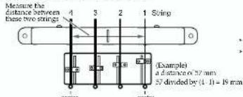
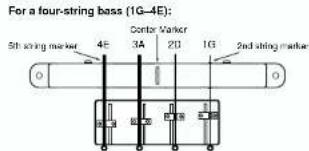
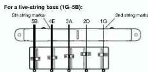
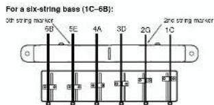
- Loosen the screws (2) in the sides of the pickup, move the markers so that they are correctly positioned according to the distance between the strings, then retighten the screws.
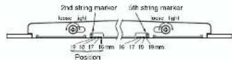
* Be careful not to tighten the string excessively. * This adjustment made so that both 2nd string marker and 5th string marker are at the same position.
Attaching the Divided Pickup
- Attach the divided pickup so that the screws on the side of the pickup face toward the neck.
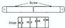
- Make sure that the divided pickup and the bridge are no more than 50 mm apart (15–25 mm is recommended).
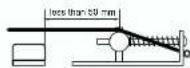
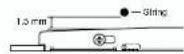
- Adjust the height of the divided pickup so that there is approximately 1.5 mm of clearance between the string and pickup when the string is pressed on the highest fret.
- In order to position the center marker as shown in the following figure, attach the divided pickup with the 2nd string marker and 5th string marker directly under the specified strings.
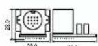
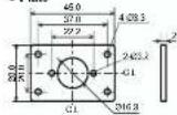
Dimensions
Unit: mm
- Plate

- Screw
Pan Semi M3 x 10
- Screw (for installing the Divided Pickup)
Tapping Pan M3 x 20
• Spring (for installing the Divided Pickup)
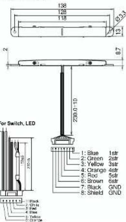
Wirings

- Divided Pickup
- USING THE UNIT SAFELY
- ALWAYS OBSERVE THE FOLLOWING
- WARNING
- CAUTION
- Supplied parts contents
- Parts should be arranged separately
- Dimensional Drawing of the Hole
- Installation Notes
- GK Connector Board
- For Bass Signal Wiring
- About Transcription for Each Controller
- For GK Volume Wiring
- For Switch, LED Wiring
- GK-KIT-BG
- Roland®
- Owner's Manual
- IMPORTANT NOTES
- Adjusting the Divided Pickup
- Attaching the Divided Pickup
- Dimensions
Brand : ROLAND
Model : GK-KIT-BG3
Category : Musical accessory