
MDSC-1119 - Monitor Barco - Free user manual and instructions
Find the device manual for free MDSC-1119 Barco in PDF.


| Product Type | Medical-grade LCD Monitor |
| Display Size | 19 inches (diagonal) |
| Resolution | 1280 x 1024 (SXGA) |
| Aspect Ratio | 5:4 |
| Inputs | VGA, DVI-D, S-Video, Composite, SDI, HDMI (via adapter) |
| Contrast Ratio | 1000:1 (typical) |
| Brightness | 300 cd/m² (typical) |
| RS232 Control | Yes, via ASCII protocol (3-wire, no handshaking) |
| Power Supply | AC 100-240V, 50/60 Hz |
| Power Consumption | <50W (typical) |
| Weight | Approximately 8 kg (with stand) |
| Dimensions (W x H x D) | 430 x 430 x 200 mm (with stand) |
| Adjustable Functions | Brightness, Contrast, Saturation, Hue, Sharpness, Phase, Frequency, Color Temperature, Gamma, DICOM |
| Special Features | Picture-in-Picture (PIP), GPIO, OSD languages (EN, FR, DE, ES) |
| Cleaning | Use soft cloth with mild cleaner; avoid abrasive liquids or solvents |
| Safety | Do not open; risk of electric shock; use grounded outlet |
| Spare Parts & Repairability | Contact Barco service for replacement parts; no user-serviceable parts inside |
Frequently Asked Questions - MDSC-1119 Barco
User questions about MDSC-1119 Barco
0 question about this device. Answer the ones you know or ask your own.
Ask a new question about this device
Download the instructions for your Monitor in PDF format for free! Find your manual MDSC-1119 - Barco and take your electronic device back in hand. On this page are published all the documents necessary for the use of your device. MDSC-1119 by Barco.
USER MANUAL MDSC-1119 Barco
MDSC-1119 and MDSC-2124
ASCII Communication Protocol Manual
K5904075-05
January 2009
Table of contents
-
ABOUT THIS MANUAL 5
-
RS232 INFORMATION 5
2.1. Connection of Signals 5
2.2. Data Format.... 5
- COMMAND PROTOCOL....5
3.3. Different Command Types....6
3.3.1. Control command (CMD) 6
3.3.2. Read Value command (RV) 7
3.3.3. Minimum command (Mm)......8
3.3.4. Maximum command (MM) 9
- OVERVIEW OF COMMANDS 10
4.4. Input Selection commands 10
4.4.1. INP 10
4.4.2. INPA 11
4.5. Adjustments commands.... 12
4.5.1. BRI 12
4.5.2. CON....13
4.5.3. SAT (Color in OSD) 13
4.5.4. HUE 14
4.5.5. SRP....15
4.5.6. APOS (Autosetup) 15
4.5.7. AGC (Autosetup).... 15
4.5.8. APHA (Autosetup) 16
4.5.9. NXP (Autosetup) 16
4.5.10.SCL 16
4.5.11.SCLA 17
4.5.12. ASRI 18
4.5.13.ASRV 18
4.6. PIP commands.... 19
4.6.1. PIPL.... 19
4.6.2. PIPSL 20
4.6.3. PIPDL....20
4.6.4. PIPI 21
4.6.5. PIPS....21
4.6.6. PIPH 22
4.6.7. PIPV....23
4.6.8. PIPB....23
4.6.9. PIPO 24
4.6.10. PIPT....24
4.6.11. PIPN 25
4.7. User Profile commands.... 25
4.7.1. PRO 25
4.7.2. PRN 26
4.7.3. DPR 26
4.7.4. SNP 27
4.7.5. SCP 27
4.8. Advanced commands 27
4.9. Setup commands 32
4.9.1. ENI 32
4.9.2. QIN....33
4.9.3. SRCS 34
4.9.4. SRCP 34
4.9.5. LED 35
4.9.6. PSM 35
4.9.7. LAN 36
4.9.8. OSDT 37
4.9.9. GPIO 37
4.9.10. GPIOT (for text mode only) 38
4.9.11. GPIOP (in text mode only)....39
4.9.12. GPIOTR 40
4.9.13.BAUD 40
4.10. Information commands 41
4.10.1. VER 41
4.11. Service commands.... 42
4.11.1.FRML 42
4.11.2. KEYB 42
4.11.3. KEY.... 43
4.11.4. KEYM 43
4.11.5.GMT 44
4.11.6. BWC 45
4.11.7.BWV 45
4.11.8. CLP 46
4.11.9.CLMP....46
4.11.10. CLMPV 47
4.12. ASCII Specific Commands.... 47
1. About this manual
The RS232 ASCII communication protocol is available with all MDSC displays. It can be used through customized RS232 software or by entering the necessary ASCII characters through terminal software such as Realterm.
2. RS232 Information
2.1. Connection of Signals
The MDSC uses a RS232 connection type of 3-wires (RX / TX / GND) without handshaking. The request to send (RTS) line and clear to send (CTS) line are also not used by the MDSC.
2.2. Data Format
Data Length: 8 bits
Transmission Method: Asynchronous
Start bit: 1 bit
Stop bit: 1 bit
No Handshaking
Characters used are part of the ASCII 256 standard
* Transmission Speed: 9600/19200/38400/57600/115200
* Note: Changing the transmission speed or baud rate of the RS232 communication in your system requires also changing the transmission speed through the OSD menu of the MDSC.
3. Command Protocol
Designated ASCII characters determine when a complete command string begins and ends. The command string must start with the “&&” ASCII characters and end with the “;” ASCII character. A “,” is used to separate each of the parameters from the command and from each other.
Commands can be sent sequentially as long as the entire command string is started with a “&&” and terminated by “;”. A “:” should be used to separate each comma. When writing multiple commands you only need “&&” at the start of the first command.
Response
Each command will generate some kind of response. This response is a string of ASCII characters that may contain an error, warning or status message depending on which commands and parameters are sent. Responses are always in the same format:
The first byte is always 0x51 and the third byte 0xC1. The second byte contains the number of bytes in the response + 0x80. The actual response message will be byte 4 onwards. The expected response (Byte4 to Byte n) is explained for each command in the command section of this document.
3.3. Different Command Types
Each command for the MDSC can be of 4 different types. Specifying these different types at the beginning of a command allows the user to use the same command to execute an action, read status information, or determine minimum and maximum values.
The following examples describe how the backlight percentage value can be controlled (written), read and how the minimum and maximum value can be determined. To do this the 4 types of the same ASCII command "BKL" are used.
3.3.1. Control command (CMD)
When the “CMD” characters are sent at the beginning of the command an action or change of setting is executed. Usually the returned response is the newly set value but this depends on which command is sent. Responses for each command are explained individually in the following document.
If no CMD, RV, Mm or MM is sent at the beginning of the command the command type is assumed to be that of a control command.
Commands can be various lengths. The display will always determine the length of a command by the designated beginning “&&” and ending ASCII characters “:” or “;”.
Control Command Example
This control command sets the value of the backlight to 75%. In the OSD the backlight can be changed in the Advanced menu with the menu item "Luminance". Notice that
the parameter to set the value "75" is only needed for a "CMD" or write type command. Sending extra parameters that are not needed will generate an error message response.
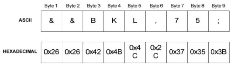
The same command can also be written as follows:

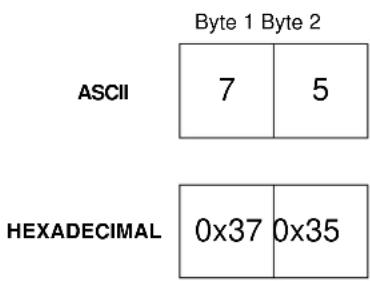
Control Command Response
The new Backlight value written is the response.
3.3.2. Read Value command (RV)
When the “RV” (read value) characters are sent at the beginning of the command the response returns the value or status and does not execute any action.
RV Command Example
To use the same command to read the ASCII characters "RV" are sent just after the two start characters "&&" and separated from the "BKL" command with a ",".
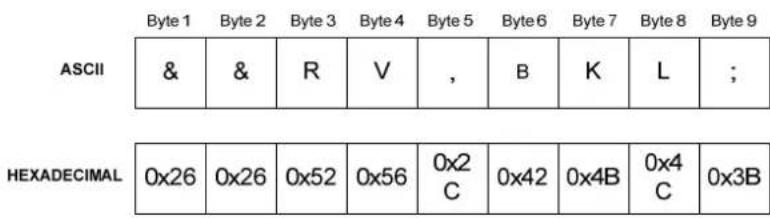
The "RV" must always be included in a read command. When the command type is not specified the command always defaults to a "CMD".
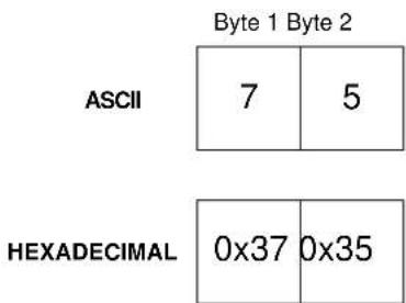
Response for RV command
The read command for the backlight value reads the current % value at which the backlight is set (in this case the same as control command above).
3.3.3. Minimum command (Mm)
When the “Mm” (minimum) characters are sent at the beginning of the command the response returns the minimum possible value of the parameter that can be entered in the command, as with RV commands no action is taken.
Mm Command Example
The minimum command is used to determine the smallest possible value at which the backlight can be adjusted. As with the read command Mm is sent directly after the two start characters and separated from the command with a comma.
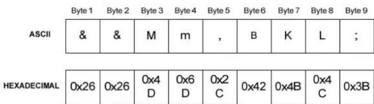
Response for Mm command
This minimum command responds with the minimum % at which the backlight can be adjusted.
ASCII
0
HEXADECIMAL
0x30
3.3.4. Maximum command (MM)
When the “MM” characters are sent at the beginning of the command the response returns the maximum possible value of the parameter that can be entered in the command, as with RV commands no action is taken.
MM Command
The maximum command is used to determine the highest possible value at which the backlight can be adjusted.
Response for MM command
This maximum command returns for the maximum % the backlight can be displayed.
ASCII
1 | 0 | 0
HEXADECIMAL
| 0x31 | 0x30 | 0x30 |
Most commands are available with the type CMD, RV, Mm, and MM. However, as the table at the end of this document shows some may only be valid at certain types. An example of this is the "INPN" command, which reads the name of the input and is read (RV) only. If the command type is sent for a command which is not available an error message will be returned.
4. Overview of Commands
4.4. Input Selection commands
The following commands give you comparable to control as with the Input Selection menu in the OSD.
4.4.1. INP
This command can be used to select an input. The input corresponding to each number depends on the configuration of the display and can be determined by the read (RV) command. Unlike the OSD all inputs, even disabled ones can be selected.
| Command Input Type | |
| CMD 1 - max number of inputs available | |
| RV | INP |
| MM | |
| Mm | |
- CMD
Selects the input and returns with the input name Example: CMD, INP, 1 Response: VGA
• RV
Reads the currently selected input name. Example: RV, INP Response: VGA
• MM
Returns the maximum input number. Example: MM, INP Response: 13
• Mm
Returns the minimum input number. Example: Mm, INP Response: 1
4.4.2. INPA
This command allows the user to enter or read an alias name for the current input.
| Command Input Type Alias Name | |
| CMD 1 - max number of inputs availableRV INPAMMm | Alias Name |
- CMD
Sets the alias name
Example: CMD, INPA, 1, Camera1
Response: 0:Camera1
• RV
Reads the currently selected alias name.
Example: RV, INPA, 1
Response: 0:Camera1
• MM
Returns the maximum number of characters in the alias name.
Example: MM, INPA
Response: 12
• Mm
Returns the minimum number of characters in the alias name.
Example: Mm, INP
Response: 0
4.4.3. INPN
The input name command (INPN) can be used to determine what input is attached to what number. The INPN command returns a string depending on the input assigned to that number.
For example if one wants to know what input number 1 corresponds to, the command "RV, INPN, 1" can be used, and the input name string (for example VGA) will be returned. INPN is a read command only; the names read cannot be changed.
| Command Input Type Note | ||
| RV 1 -IMAN number of inputs available | Inputs will always start at 1; if there are fewer inputs available "Input source number outside range" will be sent. | |
• RV
Reads the input name assigned to the sent number.
Example: RV, INPN, 1
Response: VGA
The following strings can be returned:
- VGA
- Grayscale
- RGB
- RGBHV
- S-Video 1
- S-Video 2
- YPrPb
- CVBS1
- CVBS2
- CVBS3
- SDI
- DVI analog
- DVI digital
- HD-SDI
- TestPattern
4.5. Adjustments commands
The following commands give you comparable to control as with the Adjustments menu in the OSD.
4.5.1. BRI
Adjusts and gets information about the brightness of the display.
| Command Minimum to Maximum Brightness | |
| CMD 0 - 200 | |
| RV BRI | |
| MM | |
| Mm | |
- CMD
Sets brightness value
Example: CMD, BRI, 50
Response: 50
• RV
Reads the current brightness
Example: RV, BRI
Response: 50
• MM
Returns the maximum brightness
Example: MM, BRI
Response: 200
• Mm
Returns the minimum brightness
Example: Mm, BRI
Response: 0
4.5.2. CON
Adjusts and gets information about the contrast of the display.
| Command Minimum to Maximum Contrast | |
| CMD 0 - 200 | |
| RV CON | |
| MM | |
| Mm | |
- CMD
Sets contrast value
Example: CMD, CON, 50
Response: 50
• RV
Reads the current contrast
Example: RV, CON
Response: 50
• MM
Returns the maximum contrast
Example: MM, CON
Response: 200
• Mm
Returns the minimum contrast
Example: Mm, CON
Response: 50
4.5.3. SAT (Color in OSD)
Adjusts and gets status about the saturation/color for the display.
| Command Minimum to Maximum Saturation | |
| CMD 0 - 200 | |
| RV SAT | |
| MM | |
| Mm | |
- CMD
Sets saturation value Example: CMD, SAT, 50 Response: 50
• RV
Reads the current saturation Example: RV, SAT Response: 50
• MM
Returns the maximum saturation Example: MM, SAT Response: 200
• Mm
Returns the minimum saturation Example: Mm, SAT Response: 0
4.5.4. HUE
Adjusts and gets information about the hue of the display.
| Command Minimum to Maximum Hue | |
| CMD 0 - 200 | |
| RV HUE | |
| MM | |
| Mm | |
- CMD
Sets hue value Example: CMD, HUE, 50 Response: 50
• RV
Reads the current hue Example: RV, HUE Response: 50
• MM
Returns the maximum hue Example: MM, HUE Response: 200
• Mm
Returns the minimum hue Example: Mm, HUE Response: 0
4.5.5. SRP
Adjusts and gets information about the sharpness of the display.
| Command Minimum to Maximum Sharpness | |
| CMD 0 - 20 | |
| RV SRP | |
| MM | |
| Mm | |
- CMD
Sets sharpness value Example: CMD, SRP, 10 Response: 10
• RV
Reads the current sharpness Example: RV, SRP Response: 10
• MM
Returns the maximum sharpness Example: MM, SRP Response: 20
• Mm
Returns the minimum sharpness Example: Mm, SRP Response: 0
4.5.6. APOS (Autosetup)
Automatically adjusts the geometry of the image input. Make sure a valid test pattern such as a full white image is displayed.
| Command | ||
| CMD | APOS | |
- CMD
Starts auto position (geometry) calculation Example: CMD, APOS Response: n/a
4.5.7. AGC (Autosetup)
Automatically adjusts the gain of the image input. Make sure a valid test pattern, one containing at least 1 8x8 group of pixels of full black and full white.
| Command | ||
| CMD | AGC | |
- CMD
Starts auto gain calculation
Example: CMD, AGC
Response: n/a
4.5.8. APHA (Autosetup)
Automatically adjusts the phase of the image input. Make sure a valid test pattern is displayed.
| Command | ||
| CMD | APHA | |
- CMD
Starts auto position (geometry) calculation
Example: CMD, APHA
Response: n/a
4.5.9. NXP (Autosetup)
This command selects next preset or nearest scan that matches from internal VESA table. It can also be used to determine if a user mode is being used by seeing if the number read is 1-10.
| Command | ||
| CMD | NXP | |
| RV | ||
- CMD
Sets next preset or scan settings
Example: CMD, NXP
Response: 0 (depending on input type and user mode)
• RV
Reads the current preset value
Example: RV, NXP
Response: 86 (depending on input type)
4.5.10. SCL
This command determines which scaling function to use.
| Command Scale Number Resulting Scaling | |
| CMD 1 | |
| 2 = Native = Best Fit | |
| 3 = Fit Height = Fit Width | |
| 4 = Full Display = Adjustable | |
| SCL | |
| 6 | |
| RV | |
| MM | |
| Mm | |
- CMD
Sets scale select value
Example: CMD, SCL, 5
Response: Scaling: Full Display
• RV
Reads the current scale select value
Example: RV, SCL
Response: Scaling: Full Display
• MM
Returns the maximum scale select value
Example: MM, SCL
Response: 6
• Mm
Returns the minimum scale select value
Example: Mm, SCL
Response: 1
4.5.11. SCLA
This function automatically selects adjustable scaling and changes the scaled value from 50% to 200%. Limitations in the Gennum will prevent scaling for some high frequency HDTV inputs.
| Command Adjustable Scaling Value | |
| CMD 50 - 200 | |
| RV SCLA | |
| MM | |
| Mm | |
- CMD
Sets scale select adjustable value. Makes scaling adjustable.
Example: CMD, SCLA, 100
Response: 100
• RV
Reads the current adjustable scaled value
Example: RV, SCLA
Response: 100
• MM
Returns the maximum scale select value
Example: MM, SCLA
Response: 200
• Mm
Returns the minimum scale select value
Example: Mm, SCLA
Response: 50
4.5.12. ASRI
This commands selects the aspect ratio of the image: Auto, 1/1,5/4,16/9 or adjustable. When using “auto” selection the best aspect ratio for an input is determined by the VESA table in the display.
| Command Aspect Ration Number Resulting ASR | ||
| CMD 0 | = Auto | |
| 1 | = 1/1 | |
| 2 | = 4/3 | |
| 3 | = 5/4 | |
| ASRI | 4 | = 16/9 |
| 5 | = Adjustable | |
| RV | ||
| MM | ||
| Mm | ||
- CMD
Sets aspect ratio
Example: CMD, ASRI, 4
Response: 4
• RV
Reads the current aspect ratio
Example: RV, ASRI
Response: 4
• MM
Returns the maximum aspect ratio
Example: MM, ASRI
Response: 5
• Mm
Returns the minimum aspect ratio
Example: Mm, ASRI
Response: 0
4.5.13. ASRV
This command changes the aspect ratio adjustable value. When the ASRV command is used the adjustable setting of ASRI (aspect ration type) is automatically set. Values go from 800-2000.
| Command Aspect ratio value | |
| CMD 800 - 2000 | |
| RV ASRI | |
| MM | |
| Mm | |
- CMD
Sets aspect ratio adjustable value
Example: CMD, ASRV, 1200
Response: 1200
• RV
Reads the current aspect ratio adjustable value
Example: RV, ASRV
Response: 1200
• MM
Returns the maximum aspect ratio adjustable value
Example: MM, ASRV
Response: 2000
• Mm
Returns the minimum aspect ratio adjustable value
Example: Mm, ASRV
Response: 800
4.6. PIP commands
The following commands control the PIP (picture in picture) settings and can be found in the PIP submenu of the OSD.
4.6.1. PIPL
This command sets and reads information about the PIP layout. There are 7 different PIP layouts available. Layout 0 is always PIP off. The other layouts 1 - 4 can be saved by the user.
| Command Layout number Resulting Layout | ||
| CMD 0 | = off | |
| 1 | = Layout 1 | |
| 2 | = Layout 2 | |
| 3 | = Layout 3 | |
| 4 | = Layout 4 | |
| RV | ||
| MM | ||
| Mm | ||
- CMD
Sets PIP layout value
Example: CMD, PIPL, 4
Response: 4
• RV
Reads the current PIP layout
Example: RV, PIPL
Response: 4
• MM
Returns the maximum PIP layout number
Example: MM, PIPL
Response: 4
• Mm
Returns the minimum PIP layout number
Example: Mm, PIPL
Response: 0
4.6.2. PIPSL
PIPSL will save the current PIP layout to the active PIP layout number. The layout you wish to save must be active when the PIPSL command is executed.

- CMD
Saves current PIP layout
Example: CMD, PIPSL
Response: 3 (when PIP layout 4 is set)
• RV
Reads the current PIP layout number
Example: RV, PIPSL
Response: 3 (when PIP layout 4 is set)
4.6.3. PIPDL
This command deletes an active PIP layout. The layout you wish to delete must be active when the PIPDL command is executed.
| Command | |
| CMD | PIPDL |
| RV | |
- CMD
Deletes current PIP layout
Example: CMD, PIPDL
Response: 3 (when PIP layout 3 is set)
• RV
Reads the current PIP layout number
Example: RV, PIPDL
Response: 3 (when PIP layout 3 is set)
4.6.4. PIPI
This command changes the PIP input type of either PIP image 1 or PIP image 2.
| Command PIP Image Input | ||||||||||
| CMD | 1 | / | 2 | 1 | - | 13 | ||||
| RV | 1 | / | 2 | |||||||
| MM | 1 | / | PIPI | |||||||
| Mm | 1 | / | 2 | |||||||
- CMD
Sets PIP input
Example: CMD, PIP1, 1, 7
Response: CVBS1
• RV
Reads the current PIP input
Example: RV, PIPI, 1
Response: CVBS1
• MM
Returns the maximum PIP layout number
Example: MM, PIP1, 1
Response: 13
• Mm
Returns the minimum PIP layout number
Example: Mm, PIPI, 2
Response: 1
4.6.5. PIPS
This command reads and adjusts the PIP size from 10% to maximum image size. Since some input types have limited scaling, maximum size may not be 100%. When this happens the maximum size is returned
| Command PIP Image Input | ||||||||
| CMD | 1 | / | 2 | 10 | - | 100 | ||
| RV | 1 | / | 2 | |||||
| MM | 1 | / | PIPS | |||||
| Mm | 1 | / | 2 | |||||
- CMD
Sets PIP size
Example: CMD, PIPS, 1, 50
Response: 50
• RV
Reads the current PIP size
Example: RV, PIPS, 1
Response: 50
• MM
Returns the maximum PIP size
Example: MM, PIPS, 1
Response: 94 (if maximum size is 94%)
Example: MM, PIPS, 2
Response: 100 (if maximum size is 100%)
• Mm
Returns the minimum PIP size
Example: Mm, PIPI, 2
Response: 10 (cannot be less than 10%)
4.6.6. PIPH
This command moves the PIP image 1 or 2 to a new horizontal position on screen. The valid locations for a PIP image depend on its size and aspect ratio. The PIP cannot be moved outside the active display screen. The valid locations are automatically calculated and can be read using the MM and Mm commands.
* Note: Going outside the active area will go to maximum and return maximum value.
| Command PIP Image Min - Max x value | ||||
| CMD | 1 / 2 | min x - max x | ||
| RV | 1 / 2 | |||
| MM | 1 / 2 | |||
| Mm | 1 / 2 | |||
- CMD
Sets PIP horizontal coordinate
Example: CMD, PIPH, 2, 300
Response: 300
• RV
Reads the current PIP horizontal coordinate
Example: RV, PIPH, 2
Response: 300
• MM
Returns the maximum PIP horizontal coordinate
Example: MM, PIPH, 2
Response: 897 (maximum horizontal location keeping PIP in active area may be different depending on size and input)
• Mm
Returns the minimum PIP horizontal coordinate
Example: Mm, PIPH, 2
Response: 0
4.6.7. PIPV
This command moves the PIP image 1 or 2 to a new vertical position on screen. T valid locations for a pip image depend on its size and aspect ratio. The PIP cannot be moved outside the active display screen. The valid locations are automatically calculated and can be read using the MM and Mm commands.
* Note: Going outside the active area will go to maximum and return maximum value.
| Command PIP Image Min - Max y value | |||
| CMD 1 / 2 min y - max y | |||
| RV 1 / 2 | |||
| MM 1 / 2 | |||
| Mm | 1 / 2 | ||
- CMD
Sets PIP vertical coordinate
Example: CMD, PIPV, 2, 500
Response: 500
• RV
Reads the current PIP vertical coordinate
Example: RV, PIPV, 2
Response: 500
• MM
Returns the maximum PIP vertical coordinate
Example: MM, PIPV, 2
Response: 717 (maximum vertical location keeping PIP in active area)
• Mm
Returns the minimum vertical coordinate
Example: Mm, PIPV, 2
Response: 0
4.6.8. PIPB
This command changes the PIP border color to white, red, green, blue, yellow, orange or none.
| Command PIP | Image | Color Number | Resulting Border Color | |
| CMD | 1 / 2 | 0 | = none | |
| 1 / 2 | 1 | = white | ||
| 1 / 2 | 2 | = red | ||
| 1 / 2 | 3 | = green | ||
| 1 / 2 | 4 | = blue | ||
| PIPB | 1 / 2 | 5 | = yellow | |
| 1 / 2 | 6 | = orange | ||
| RV | 1 / 2 | |||
| MM | ||||
| Mm | ||||
- CMD
Sets PIP border color Example: CMD, PIPB, 2, 4 Response: 2: Blue
• RV
Reads the current PIP border color Example: RV, PIPB, 1 Response: 1: None
• MM
Returns the maximum PIP border color Example: MM, PIPB Response: 7
• Mm
Returns the minimum PIP border color Example: Mm, PIPB Response: 0
4.6.9. PIPO
Changes PIP order Image 1 and Image 2. The image selected is put in front of the image not selected.
| Command PIP Image on top | |
| CMD 1 /2PIPORV | |
- CMD
Sets PIP order Example: CMD, PIPO, 1 Response: 1
• RV
Reads the current PIP order Example: RV, PIPO Response: 2
4.6.10. PIPT
Toggles PIP inputs so that image 1 input becomes image 2 input and the PIP images displayed swap. Since certain adjustments outside the PIP menu can only be made on image 1 it is necessary to switch the priority of inputs to make changes to the input on image 2.
| Command | |
| CMD PIPT |
- CMD
Toggles PIP inputs Example: CMD, PIPT Response: ACK (when successful)
4.6.11. PIPN
This command allows you to change the PIP layout name for the current PIP layout.
| Command PIP Layout Name | |
| CMD | PIP Layout Name |
| RV | PIPN |
| MM | |
| Mm | |
- CMD
Sets the PIP layout name
Example: CMD, PIPN, PIP Name
Response: PIP Name
• RV
Reads the currently selected PIP layout name.
Example: RV, PIPN
Response: PIP Name
• MM
Returns the maximum number of characters in the alias name.
Example: MM, PIPN
Response: 10
• Mm
Returns the minimum number of characters in the PIP layout.
Example: Mm, PIPN
Response: 1
4.7. User Profile commands
4.7.1. PRO
This command selects a profile 0-20. Profile 0 is profile off. Profiles are only selectable if they have been previously filled and saved (same as OSD).
| Command Profile Number | |
| CMD 0 - 20 | |
| RV PRO | |
| MM | |
| Mm | |
- CMD
Selects profile returns profile number. If profile is not active error
9 is returned.
Example: CMD, PRO, 3
Response: 3
• RV
Reads the currently selected profile number
Example: RV, PRO
Response: 3
• MM
Returns 0 - 20 for the number of profiles occupied.
Example: MM, PRO
Response: 4
• Mm
Returns 0 or profile off
Example: Mm, PRO
Response: 0
4.7.2. PRN
This command changes the profile name it is only available when an existing profile is selected.
| Command Name | ||
| CMD | Profile | Name |
| RV | PRN | |
| MM | ||
| Mm | ||
- CMD
Sets the profile name
Example: CMD, PRN, My Profile
Response: My Profile
• RV
Reads the currently selected profile name.
Example: RV, PRN
Response: My Profile
• MM
Returns the maximum number of characters in the profile name.
Example: MM, PRN
Response: 11
• Mm
Returns the minimum number of characters in the profile name.
Must be at lease 1 character long.
Example: Mm, PRN
Response: 1
4.7.3. DPR
This command deletes the selected profile.
| Command | ||
| CMD | DPR | |
- CMD
Deletes and profile returns number
Example: CMD, DPR, 3
Response: 3 (when profile 3 is selected)
4.7.4. SNP
This command saves a new profile in the first available (not used or deleted) profile.
| Command | |
| CMD | SNP |
- CMD
Saves the current settings as a new profile returns number
Example: CMD, SNP
Response: 3
4.7.5. SCP
This command saves the profile in the current profile selected. All existing values for that profile will be overwritten.
| Command | ||
| CMD | SCP | |
- CMD
Saves the current settings and overwrites currently selected profile.
Example: CMD, SCP
Response: 3
4.8. Advanced commands
4.8.1. BKL (Luminance in OSD)
Adjusts and gets status about the backlight settings (luminance in the OSD) for the display.
| Command Minimum – Maximum Luminance | |
| CMD 0 - 100 | |
| RV BRI | |
| MM | |
| Mm | |
- CMD
Sets luminance value
Example: CMD, BKL, 50
Response: 50
• RV
Reads the current luminance
Example: RV, BKL
Response: 50
• MM
Returns the maximum luminance
Example: MM, BKL
Response: 100
• Mm
Returns the minimum luminance
Example: Mm, BKL
Response: 0
4.8.2. PHZ
Adjusts and gets status about the phase settings of the display.
| Command Minimum - Maximum Phase | |
| CMD 0 - 31 | |
| RV PHZ | |
| MM | |
| Mm | |
- CMD
Sets phase value
Example: CMD, PHZ, 15
Response: 15
• RV
Reads the current phase value
Example: RV, PHZ
Response: 15
• MM
Returns the maximum phase value
Example: MM, PHZ
Response: 31
• Mm
Returns the minimum phase value
Example: Mm, PHZ
Response: 0
4.8.3. FRQ
Adjusts and gets status about the frequency settings of the display.
| Command Minimum – Maximum Frequency | |
| CMD 500 – 2800 | |
| RV FRQ | |
| MM | |
| Mm | |
- CMD
Sets frequency value
Example: CMD, FRQ, 400
Response: 400
• RV
Reads the current frequency value
Example: RV, FRQ
Response: 400
• MM
Returns the maximum frequency value
Example: MM, FRQ
Response: 2800
• Mm
Returns the minimum frequency value
Example: Mm, FRQ
Response: 500
4.8.4. CTMPV
This command selects the active color temperature: Full White, 5300K, 6500K, 9300K, Clear Base, Blue Base, User or any of the adjustable values. Certain values such as 5300K, 6500K and 9300K can be selected by 2 different values to remain compatible with previous versions of firmware that do not have extended color values.
Command Color Temperature Number
CMD [1] = Full White/Native White
[2] = 5300K
[3] = 6500K
[4] = 9300K
[5] = Clear Base
[6] = Blue Base
[7] = Adjustable (last adjustable value set)
[8] = User
[9] = 5000K
[10] = 5200K
[11] = 5300K
[12] = 5400K
[13] = 5600K
[14] = 5800K
[15] = 6000K
[16] = 6200K
[17] = 6400K
[18] = 6500K
[19] = 6600K
[20] = 6800K
[21] = 7000K
[22] = 7500K
[23] = 8000K
[24] = 8500K
[25] = 9000K
[26] = 9300K
[27] = 9500K
[28] = 10000K
RV
MM
Mm
- CMD
Sets color type value
Example: CMD, CTMPV, 9
Response: 5000K
• RV
Reads the current color type value
Example: RV, CTMPV
Response: 5000K
• MM
Returns the maximum color type value
Example: MM, CTMPV
Response: 28
• Mm
Returns the minimum color type value
Example: Mm, CTMPV
Response: 1
4.8.5. UCTMP
This command can be used to adjust the user color temperature. When the user color temperature is changed it will automatically become the active color temperature type. In other words if the color type is set to native white it will change to user to show the new values.
| Command Red | Green Blue | ||
| CMD | CTMPV | 10 - 1000 10 - 1000 10 - 1000 | |
| RV | |||
| MM | |||
| Mm | |||
- CMD
Sets the user color temp value and writes values to R,G,B gains
Example: CMD, UCTMP, 780, 200, 1000
Response: User:780;200;1000
• RV
Reads the current color user type gain values
Example: RV, UCTMP
Response: User:780;200;1000
• MM
Returns the maximum gain value
Example: MM, UCTMP
Response: 1000
• Mm
Returns the minimum gain value
Example: Mm, UCTMP
Response: 10
4.8.6. DFC
Selects display function: Native, Gamma or DICOM.
| Command Display Function | |
| CMD | [1] = Native |
| [2] = Gamma | |
| [3] = DICOM | |
| DFC | |
| RV | |
| MM | |
| Mm | |
- CMD
Sets display function / LUT type
Example: CMD, DFC, 3
Response: DICOM
• RV
Reads the current display function / LUT type
Example: RV, DFC
Response: [1-3]
• MM
Returns the maximum display function / LUT type
Example: MM, DFC
Response: 3
• Mm
Returns the minimum display function / LUT type
Example: Mm, DFC
Response: 1
4.8.7. DFG
Display gamma value, automatically selects Gamma for display function.
| Command Minimum to Maximum Gamma Value | |
| CMD | 100 - 300 |
| RV DFG | |
| MM | |
| Mm | |
- CMD
Sets gamma value
Example: CMD, DFG, 240
Response: Gamma:240
• RV
Reads the current gamma value
Example: RV, DFG
Response: Gamma:240
• MM
Returns the maximum gamma value
Example: MM, DFG
Response: 300
• Mm
Returns the minimum gamma value
Example: Mm, DFG
Response: 100
4.8.8. RST
This command restores the factory settings of the display. Warning all user settings will be deleted and display will restart.
| Command | |
| CMD RST |
CMD
Restores
factory
settings
Example: CMD, RST
Response: n/a (display will restart!)
4.9. Setup commands
4.9.1. ENI
This command enables and disables inputs for the display. Only enabled inputs can be selected with the source scan, quick input select, GPIO switch or in the OSD input selection menu.
| Command Input | Enable/Disable | ||
| CMD | 1 - total number of inputs | 1 / 0 | |
| RV | ENI | ||
| MM | |||
| Mm | |||
- CMD
Enables or disables input
Example: CMD, ENI, 1, 0
Response: VGA Disabled
• RV
Reads whether the input is disabled / enabled
Example: RV, ENI, 1
Response: VGA Disabled
• MM
Returns maximum number of inputs, this can vary for display types.
Example: MM, ENI
Response: 13
• Mm
Returns the minimum input number
Example: Mm, ENI
Response: 1
4.9.2. QIN
This command enables or disables the quick input select feature using the up and down keys on the display.
| Command Enable/Disable | |
| CMD | 0 / 1 |
| RV QIN | |
| MM | |
| Mm | |
- CMD
Sets the quick input select is enabled / disabled
Example: CMD, QIN, 0
Response: 0
• RV
Reads whether the quick input select is enabled / disabled
Example: RV, QIN
Response: 0
• MM
Returns enabled value
Example: MM, QIN
Response: 1
• Mm
Returns disabled value
Example: Mm, QIN
Response: 0
4.9.3. SRCS
This command enables or disables the automatic source scan feature on the display.
| Command Enable/Disable | ||
| CMD | 0 / 1 | |
| RV | SRCS | |
| MM | ||
| Mm | ||
- CMD
Sets the source scan is enabled / disabled
Example: CMD, SRCS, 0
Response: 0
• RV
Reads whether the source scan is enabled / disabled
Example: RV, SRCS
Response: 0
• MM
Returns enabled value
Example: MM, SRCS
Response: 1
• Mm
Returns disabled value
Example: Mm, SRCS
Response: 0
4.9.4. SRCP
This command sets or determines the source priority set. Source priority is the input source that, when available will be used by the display. Choosing 0 selects no source priority. It is possible to change the input using the OSD, GPIO switch, quick input select buttons and ASCII commands but after 5 seconds the display will switch to its priority input.
| Command Input Number | |
| CMD 0 - max | number of inputs available |
| RV SRCP | |
| MM | |
| Mm | |
- CMD
Selects the input and returns with the input name
Example: CMD, SRCP, 1
Response: VGA
• RV
Reads the currently selected input name.
Example: RV, SRCP
Response: VGA
• MM
Returns the maximum input number.
Example: MM, SRCP
Response: 13
• Mm
Returns the minimum input number.
Example: Mm, SRCP
Response: 0
4.9.5. LED
This command enables and disables the power LED on the display console.
| Command Enable/Disable | |
| CMD | 0 / 1 |
| RV LED | |
| MM | |
| Mm | |
- CMD
Sets the power LED is enabled / disabled
Example: CMD, LED, 0
Response: 0
• RV
Reads whether the power LED is enabled / disabled
Example: RV, LED
Response: 0
• MM
Returns enabled value
Example: MM, LED
Response: 1
• Mm
Returns disabled value
Example: Mm, LED
Response: 0
4.9.6. PSM
This command enables or disables the power save (DPMS) mode in the display. When enabled the display will go into a low power setting and show an orange LED if there is no valid input.
| Command Enable/Disable | |
| CMD | 0 / 1 |
| RV PSM | |
| MM | |
| Mm | |
- CMD
Sets the power save mode is enabled / disabled
Example: CMD, PSM, 0
Response: 0
• RV
Reads whether the power save mode is enabled / disabled
Example: RV, PSM
Response: 0
• MM
Returns enabled value
Example: MM, PSM
Response: 1
• Mm
Returns disabled value
Example: Mm, PSM
Response: 0
4.9.7. LAN
This command can be used to select the language: English; French, German and Spanish.
| Command Language Number Resulting Language | ||
| CMD | 1 | English |
| 2 | French | |
| 3 | German | |
| LAN | 4 | Spanish |
| RV | ||
| MM | ||
| Mm | ||
- CMD
Sets the language
Example: CMD, LAN, 3
Response: 3
• RV
Reads the language setting
Example: RV, LAN
Response: 3
• MM
Returns maximum language number
Example: MM, LAN
Response: 4
• Mm
Returns minimum language number
Example: Mm, LAN
Response: 1
4.9.8. OSDT
This command selects how long it will take for the OSD to timeout or disappear after the last key press.
| Command Resulting Time Out | ||
| CMD | 1 | 15 seconds |
| 2 | 30 seconds | |
| 3 | 45 seconds | |
| OSDT | 4 | 1 minute |
| 5 | 4 minute | |
| RV | ||
| MM | ||
| Mm | ||
- CMD
Sets the OSD time out
Example: CMD, OSDT, 3
Response: 3
• RV
Reads the OSD time out
Example: RV, OSDT
Response: 3
• MM
Returns maximum OSD time out
Example: MM, OSDT
Response: 5
• Mm
Returns minimum OSD time out
Example: Mm, OSDT
Response: 1
4.9.9. GPIO
This command enables the GPIO interface selecting between 4 types of functionality: disabled, switch input, show text and PIP order. It can also read what currently selected function is for the GPIO.
* Note: When GPIO switch 1 and 2 have the same functionality only GPIO switch 1 is used.
| Command | Image | Function | Resulting GPIO type | |
| CMD | 1 / 2 | 0 | Disabled | |
| 1 | Input | |||
| 2 | Text | |||
| GPIO | 3 | PIP Order | ||
| RV | 1 / 2 | |||
| MM | ||||
| Mm | ||||
- CMD
Sets the GPIO function
Example: CMD, GPIO, 1, 3
Response: 1:PIP Order
Example: CMD, GPIO, 2, 2
Response: 2
• RV
Reads the GPIO function number
Example: RV, GPIO, 1
Response: 1
• MM
Returns maximum GPIO function number
Example: MM, GPIO
Response: 3
• Mm
Returns minimum GPIO function number
Example: Mm, GPIO
Response: 1
4.9.10. GPIOT (for text mode only)
This command enters new text or reads the text set for the GPIO text function. The text string must be less than the maximum string length which is 16 characters.
| Command Image GPIO Text | |
| CMD | 1 / 2 camera 3 |
| RV 1 / _GPIOT | |
| MM | |
| Mm | |
- CMD
Sets the GPIO text
Example: CMD, GPIOT, 1, camera 3
Response: camera 3
Example: CMD, GPIOT, 2, camera 1
Response: camera 1
• RV
Reads the GPIO text
Example: RV, GPIOT, 1
Response: camera 3
Example: RV, GPIOT, 2
Response: camera 1
• MM
Returns maximum number of characters for the GPIO text
Example: MM, GPIOT
Response: 11
• Mm
Returns minimum number of characters for the GPIO text
Example: Mm, GPIOT
Response: 1
4.9.11. GPIOP (in text mode only)
This command assigns one of six positions for the GPIO text or reads the position that is currently set. Positions start at [1] upper left corner and go clock wise to [2] upper middle, [3] upper right, [4] lower right, [5] lower middle, and [6] lower left.
New coordinates will only take affect when text is drawn again. Existing text box will be erased.
| Command Image Function | ||
| CMD | 1 / 2 | [1] = Upper left |
| [2] = Upper middle | ||
| [3] = Upper right | ||
| [4] = Lower right | ||
| [5] = Lower middle | ||
| [6] = Lower left | ||
| RV 1 / 2 | ||
| MM | ||
| Mm | ||
- CMD
Sets the GPIO position
Example: CMD, GPIOP, 1, 3
Response: 1
Example: CMD, GPIOP, 2, 6
Response: 2
• RV
Reads the GPIO position
Example: RV, GPIOP, 1
Response: 1
• MM
Returns maximum GPIO position
Example: MM, GPIOP
Response: 6
• Mm
Returns minimum GPIO position
Example: Mm, GPIOP
Response: 1
4.9.12. GPIOTR
This command selects trigger settings pulse/level for GPIO inputs.
| Command | Image | Trigger Number | Resulting Trigger Level | |
| CMD | 1 / 2 | 0 | Level | |
| 1 | Pulse | |||
| RV 1 /G2IOTR | ||||
| MM | ||||
| Mm | ||||
- CMD
Sets the GPIO trigger value
Example: CMD, GPIOTR, 1, 1
Response: 1
• RV
Reads the GPIO trigger value
Example: RV, GPIOTR, 1
Response: 1
• MM
Returns maximum GPIO trigger value
Example: MM, GPIOTR
Response: 1
• Mm
Returns minimum GPIO trigger value
Example: Mm, GPIOTR
Response: 0
4.9.13. BAUD
This command selects the RS232 baud rate values for RS232 communication.
* Note: Changing the baud rate of the display will also require a change of baud rate on your terminal or software to maintain communication.
| Command Image Function | ||
| CMD | 1 / 2 | [1] = 9600 |
| [2] = 19200 | ||
| [3] = 38400 | ||
| BAUD | [4] = 57600 | |
| [5] = 115200 | ||
| RV 1 / 2 | ||
| MM | ||
| Mm | ||
- CMD
Sets the RS232 baudrate
Example: CMD, BAUD, 3
Response: 3
• RV
Reads the RS232 baudrate
Example: RV, BAUD
Response: 3
• MM
Returns maximum number for the RS232 baudrate
Example: MM, BAUD
Response: 5
• Mm
Returns minimum number for the RS232 baudrate
Example: Mm, BAUD
Response: 1
4.10. Information commands
The following functions retrieve display information as with the Information submenu in the OSD.
4.10.1. VER
The following command gets version information. It is only a read (RV) command
| Command | ||
| RV | VER | [1] = Run code version |
| [2] = Boot code version | ||
| [3] = CPLD version | ||
| [4] = FPGA1 version | ||
| [5] = N/A | ||
| [6] = GFX versin | ||
| [7] = K5800369 version | ||
| [8] = K5800376 version | ||
| [9] = N/A | ||
| [10] = VESA version | ||
RV
Reads version number
Example: RV, VER, 1
Response: Run:V1.07
4.11. Service commands
4.11.1. FRML
This command enables and disables the frame lock mode.
| Command | ||
| CMD | 0 / 1 | |
| RV | FRML | |
| MM | ||
| Mm | ||
- CMD
Sets the frame lock mode enabled / disabled
Example: CMD, FRML, 0
Response: 0
• RV
Reads whether the frame lock mode is enabled / disabled
Example: RV, FRML
Response: 0
• MM
Returns enabled value
Example: MM, FRML
Response: 1
• Mm
Returns disabled value
Example: Mm, FRML
Response: 0
4.11.2. KEYB
This command enables and disables keyboard sound / beep.
| Command | ||
| CMD | 0 / 1 | |
| RV | KEYB | |
| MM | ||
| Mm | ||
- CMD
Sets the keyboard beep enabled / disabled
Example: CMD, KEYB, 0
Response: 0
• RV
Reads whether the keyboard beep enabled / disabled
Example: RV, KEYB
Response: 0
• MM
Returns enabled value
Example: MM, KEYB
Response: 1
• Mm
Returns disabled value
Example: Mm, KEYB
Response: 0
4.11.3. KEY
This command enables and disables keys. Press and hold up and down keys for 2 seconds to access the OSD.
| Command | ||
| CMD | 0 / 1 | |
| RV | KEY | |
| MM | ||
| Mm | ||
- CMD
Sets the keyboard enabled / disabled
Example: CMD, KEY, 0
Response: 0
• RV
Reads whether the keyboard beep enabled / disabled
Example: RV, KEY
Response: 0
• MM
Returns enabled value
Example: MM, KEY
Response: 1
• Mm
Returns disabled value
Example: Mm, KEY
Response: 0
4.11.4. KEYM
This command enables and disables menu key allowing you to use up and down keys but not enter OSD. Press and hold up and down keys for 2 seconds to access the OSD.
| Command | |
| CMD | 0 / 1 |
| RV | KEYM |
| MM | |
| Mm | |
- CMD
Sets the menu key enabled / disabled
Example: CMD, KEYM, 0
Response: 0
• RV
Reads whether the keyboard beep enabled / disabled
Example: RV, KEYM
Response: 0
• MM
Returns enabled value
Example: MM, KEYM
Response: 1
• Mm
Returns disabled value
Example: Mm, KEYM
Response: 0
4.11.5. GMT
This command adjusts gamut the balance of red and green in an image.
| Command | ||
| CMD | [70-100] | |
| RV | ||
| MM | GMT | |
| Mm | ||
- CMD
Sets the color gamut value between 70 and 100
Example: CMD, GMT, 85
Response: 85
• RV
Reads color gamut value
Example: RV, GMT
Response: 85
• MM
Returns maximum gamut value
Example: MM, GMT
Response: 100
• Mm
Returns the minimum gamut value
Example: Mm, GMT
Response: 70
4.11.6. BWC
This command selects manual or automatic control of bandwidth only available for certain inputs like VGA.
| Command | ||
| CMD | [0] = Manual | |
| [1] = Automatic | ||
| RV | BWC | |
| MM | ||
| Mm | ||
- CMD
Sets bandwidth control
Example: CMD, BWC, 0
Response: Manual
• RV
Reads bandwidth control
Example: RV, BWC
Response: Manual
• MM
Returns Automatic value
Example: MM, HDR
Response: 1
• Mm
Returns Manual value
Example: Mm, HDR
Response: 0
4.11.7. BWV
This command selects the amount of bandwidth.
| Command | ||
| CMD | 0 - 170 | |
| RV | BWV | |
| MM | ||
| Mm | ||
- CMD
Sets bandwidth value
Example: CMD, BWV, 100
Response: 100
• RV
Reads bandwidth value
Example: RV, BWC
Response: 100
• MM
Returns maximum bandwidth value
Example: MM, BWV
Response: 170
• Mm
Returns minimum bandwidth value
Example: Mm, BWV
Response: 0
4.11.8. CLP
This command clears all presets or user modes
Command
CMD
CLP
- CMD
Sets bandwidth value
Example: CMD, CLP
Response: ACK
4.11.9. CLMP
This command turns clamp width adjust on/off for certain inputs. Clamp width is only available with some input types see online user manual for details.
Command
CMD
0/1
RV
CLMP
MM
Mn
- CMD
Sets clampwidth manual
Example: CMD, CLMP, 1
Response: 1
• RV
Reads clampwidth off/on
Example: RV, CLMP
Response: 1
• MM
Returns: 1 = enabled
Example: MM, CLMP
Response: 1
• Mm
Returns: 0 = disabled
Example: Mm, CLMP
Response: 0
4.11.10. CLMPV
This command turns clamp width adjust on/off for certain inputs. Clamp width is only available with some input types see online user manual for details.
| Command | ||
| CMD | 5-100 | |
| RV | CLMPV | |
| MM | ||
| Mm | ||
- CMD
Sets clampwidth value
Example: CMD, CLMPV, 75
Response: 75
• RV
Reads clampwidth value
Example: RV, CLMPV
Response: 75
• MM
Returns: 100
Example: MM, CLMPV
Response: 100
• Mm
Returns: 5
Example: Mm, CLMPV
Response: 5
4.12. ASCII Specific Commands
4.12.1. DPMS
This command enables and disables standby mode. Coming out of standby takes several seconds.
| Command | ||
| CMD | 0/1 | |
| RV | DPMS | |
| MM | ||
| Mm | ||
- CMD
Enables / disables DPMS
Example: CMD, DPMS, 1
Response: 1
• RV
Reads DPMS status
Example: RV, DPMS
Response: 1 = display in standby 0 = display normal
• MM
Returns: 1 = enabled
Example: MM, DPMS
Response: 1
• Mm
Returns: 0 = disabled
Example: Mm, DPMS
Response: 0
4.12.2. OSD
This command gives the OSD or ASCII communication the priority on the display. At default (OSD = 0) ASCII commands sent will automatically close the OSD menu when enabled ASCII commands will have no affect and return a "NACK" when the menu is open. This can be used as a safety incase the user would like to have absolute control of the display via the OSD even when a machine is sending ASCII commands.

- CMD
Enables / disables OSD priority 1 = OSD priority 0 = ASCII priority
Example: CMD, OSD, 1
Response: 1
• RV
Reads OSD priority status
Example: RV, OSD
Response: 1 = OSD priority 0 = ASCII priority
• MM
Returns: 1 = OSD priority enabled
Example: MM, OSD
Response: 1
• Mm
Returns: 0 = priority disabled
Example: Mm, OSD
Response: 0
5. Error Checks
There are several ASCII string that will be returned when an error occurs.
"Error 1: command type not found"
"Error 2: parameter out of max range"
"Error 3: parameter out of min range"
"Error 4: wrong number of parameters"
"Error 5: wrong parameter"
"Error 6: not a valid parameter"
"Error 7: Invalid PiP Mode"
"Error 8: Not a Profile"
"Error 9: Invalid Profile"
"Error 10: Source Priority Enabled"
"Error 11: Invalid Input"
"Error 12: Select PIP or change scaling"
"Error 13: Profile Off"
"Error 14: Not a Valid Input Number"
"Error 15: Invalid GPIO"
"Error 16: Clampwidth not available"
- MDSC-1119 and MDSC-2124
- ASCII Communication Protocol Manual
- Table of contents
- User Profile commands.... 25
- Advanced commands 27
- Setup commands 32
- Information commands 41
- Service commands.... 42
- ASCII Specific Commands.... 47
- About this manual
- RS232 Information
- Connection of Signals
- Data Format
- Command Protocol
- Response
- Different Command Types
- Control command (CMD)
- Control Command Example
- Control Command Response
- Read Value command (RV)
- RV Command Example
- Response for RV command
- Minimum command (Mm)
- Mm Command Example
- Response for Mm command
- Maximum command (MM)
- MM Command
- Overview of Commands
- Input Selection commands
- INP
- - CMD
- • RV
- • MM
- INPA
- INPN
- Adjustments commands
- BRI
- CON
- SAT (Color in OSD)
- HUE
- SRP
- APOS (Autosetup)
- AGC (Autosetup)
- APHA (Autosetup)
- NXP (Autosetup)
- SCL
- SCLA
- ASRI
- ASRV
- PIP commands
- PIPL
- PIPSL
- PIPDL
- PIPI
- PIPS
- PIPH
- PIPV
- PIPB
- PIPO
- PIPT
- PIPN
- User Profile commands
- PRO
- PRN
- DPR
- SNP
- SCP
- Advanced commands
- BKL (Luminance in OSD)
- PHZ
- FRQ
- CTMPV
- UCTMP
- DFC
- DFG
- RST
- CMD
- Setup commands
- ENI
- QIN
- SRCS
- SRCP
- LED
- PSM
- LAN
- OSDT
- GPIO
- GPIOT (for text mode only)
- GPIOP (in text mode only)
- GPIOTR
- BAUD
- Information commands
- VER
- RV
- Service commands
- FRML
- KEYB
- KEY
- KEYM
- GMT
- BWC
- BWV
- CLP
- Command
- CLP
- CLMP
- 0/1
- CLMP
- MM
- Mn
- CLMPV
- ASCII Specific Commands
- DPMS
- OSD
- Error Checks
Brand : Barco
Model : MDSC-1119
Category : Monitor