KT-2015WM - Monitor Kramer - Free user manual and instructions
Find the device manual for free KT-2015WM Kramer in PDF.


User questions about KT-2015WM Kramer
0 question about this device. Answer the ones you know or ask your own.
Ask a new question about this device
Download the instructions for your Monitor in PDF format for free! Find your manual KT-2015WM - Kramer and take your electronic device back in hand. On this page are published all the documents necessary for the use of your device. KT-2015WM by Kramer.
USER MANUAL KT-2015WM Kramer
natural_image
Side view of a modern flat-screen monitor with a stand (no text or symbols visible)Contents
Contents 2
Introduction 3
Getting Started 3
Overview 5
Typical Applications 6
Defining KT-2015 / KT-2015WM 15" Touch Panel 7
KT-2015 Tabletop Mount 8
KT-2015WM On-Wall Mount 8
Mounting the KT-2015 / KT-2015WM 9
Mounting KT-2015 on a Table 9
Mounting KT-2015WM on a Wall 11
Connecting Options 13
Controlling KT-2015 / KT-2015WM 14
Using Navigation Buttons or Gestures 14
Using the Home Page 15
Exiting or Starting the Kramer Control app 15
Basic Settings of KT-2015 / KT-2015WM 16
Essential First Steps 16
Setting the Date and Time 16
Connecting to Wi-Fi or Ethernet 17
Installing an 802.1X Certificate 18
Changing the Automated Firmware Update 19
Changing the Automated Kramer Control agent update 21
Setting the Display and Keyboard Language 22
Using the Kramer Control agent (connecting to Brain) 23
Entering the Control Interface IP & Port Number 23
The Kramer Control Agent Settings 24
Using the Kramer Control Agent's API 26
Methods of Setting the Control Interface URL 28
Advanced Settings 32
Scheduling a Daily Reboot 32
Password Protecting Device Settings 32
Factory Reset & Reboot 33
Logging Activity 33
Defining an auto-start playlist 34
Modifying Display Settings 35
Switching to Native Android Mode 35
Technical Specifications 36
Introduction
Welcome to Kramer Electronics! Since 1981, Kramer Electronics has been providing a world of unique, creative, and affordable solutions to the vast range of problems that confront the video, audio, presentation, and broadcasting professional on a daily basis. In recent years, we have redesigned and upgraded most of our line, making the best even better!
Getting Started
We recommend that you:
- Unpack the equipment carefully and save the original box and packaging materials for possible future shipment.
- Review the contents of this user manual.

Go to http://www.kramerav.com/downloads/KT-2015 to check for up-to-date user manuals, application programs, and to check if firmware upgrades are available (where appropriate).
Achieving Best Performance
- Use only good quality connection cables (we recommend Kramer high-performance, high-resolution cables) to avoid interference, deterioration in signal quality due to poor matching, and elevated noise levels (often associated with low quality cables).
- Do not secure the cables in tight bundles or roll the slack into tight coils.
- Avoid interference from neighboring electrical appliances that may adversely influence signal quality.
- Position your Kramer KT-2015 / KT-2015WM away from moisture, excessive sunlight and dust.
Recycling Kramer Products
The Waste Electrical and Electronic Equipment (WEEE) Directive 2002/96/EC aims to reduce the amount of WEEE sent for disposal to landfill or incineration by requiring it to be collected and recycled. To comply with the WEEE Directive, Kramer Electronics has made arrangements with the European Advanced Recycling Network (EARN) and will cover any costs of treatment, recycling and recovery of waste Kramer Electronics branded equipment on arrival at the EARN facility. For details of Kramer's recycling arrangements in your particular country go to our recycling pages at https://www.kramerav.com/social-responsibility/environment/.
Safety Instructions
This unit is intended to be supplied by:
- UL / IEC 62368-1 certified Class II power adapter suitable for use at an ambient temperature of 40°C and altitude of 5,000 m whose output meets ES1, and is rated 12 V DC, minimum 3 A.
- UL / IEC 62368-1 certified PoE output power supply suitable for use at an ambient temperature of 40°C and altitude of 5,000 m whose output meets ES1, and is rated 44-57 V DC, minimum 0.6 A.

Caution:
- This equipment is to be used only inside a building. It may only be connected to other equipment that is installed inside a building.
- For products with relay terminals and GPI\O ports, please refer to the permitted rating for an external connection, located next to the terminal or in the User Manual.
- There are no operator serviceable parts inside the unit.
- Risk of explosion if the battery is replaced by an incorrect type. Wait one-half hour after switching off before handling parts.

Warning:
- Do not open the unit. High voltages can cause electrical shock! Servicing by qualified personnel only.
- Use only PoE or the optional power adapter that is supplied with the unit.
- When using the optional power adapter, unplug it before installing the unit.

Laser Safety:
- This product complies with FDA performance standards for laser products except for conformance with IEC 60825-1 Ed. 3., as described in Laser Notice No. 56, dated May 8, 2019.
- Date of manufacture: The date code at the bottom of the product label represents the manufacturing date of this laser product.

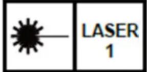
Caution: Invisible laser radiation when open. Avoid exposure to beam. Class 1 laser product. This system must be opened only by qualified technicians to prevent accidents caused by the laser beam.
Caution: Use of controls or adjustments or performance of procedures other than those specified herein may result in hazardous radiation exposure.
The ambient light sensor can automatically adjust panel brightness based on the environment.
See Display Settings to enable automatic brightness.
The Laser proximity sensor will detect nearby motion to wake the panel up without requiring a touch.
Overview
Congratulations on purchasing your Kramer KT-2015 / KT-2015WM 15" Touch Panel.
KT-2015 / KT-2015WM is a new powerful, 10-inch, IPS, multi-touch, touch panel with 1920x1080 resolution. Elegantly designed for decorative room integration, this portable touch panel can be deployed either on a tabletop or wall.
KT-2015 / KT-2015WM, with the latest Android 11, supports wired PoE (Power over Ethernet) and advanced Wi-Fi connectivity options. The touch panel has a built-in speaker and camera and comes either with a tabletop or a wall mount. The touch panel is easy to assemble, using elegant wiring, secured mounting, reliable operation and flexible deployment.
KT-2015 / KT-2015WM is a touch panel that is ideal for any 24/7 Kramer-supported commercial AV or control application and features a user-friendly, fully customizable graphical user interface configured by Kramer software.
Exceptional Quality
- Elegant Design – Smooth integration with room furniture, either on tables or walls, with flexible panel cabling and locking design options.
- Superior User Experience – IPS 1920x1080 hi-resolution screen with ±80° horizontal and vertical wide viewing angles, built-in lighting sensor for auto-adaptable brightness, and advanced multi-touch points and 2-finger gesture capabilities.
- Powerful Processing – i.MX8M Plus Quad Core A53, 4GB RAM, 32GB ROM processing performance, smoothly running complicated media and graphics-rich applications, such as H.265 video, audio streams encoding and decoding, and seamless hi-resolution 5Mp FF camera operation.
- Flexible Services – Latest Android 11 operating system. Advanced and User-friendly Operation
- Easy Installation – Powering and connectivity via a single Ethernet cable.
- Flexible Mounting – Including table or wall mounts.
- Optional Connectivity – Simple wireless Bluetooth 5 as well as connection to USB peripheral devices for either table or wall–mount installations, using the included USB cable.
- Reliable Networking – Seamless switching between wired and wireless 802.11ac connectivity.
- Versatile Powering Options – PoE and power adapter (sold separately).
- Auto Sensing – Optimized performance and operation according to automatically detected LAN speed.
- Firmware Upgrade – Define automatic updates on a predefined time of the day or update manually using USB port.
Security
- Secured Operation – Highly secured operation of applications using password protection, hidden control buttons and more. Red LED alert when camera is active.
- Secured Deployment – Flexible locking options to prevent unwanted panel-mount removal, elegantly designed to remain out of site.
Typical Applications
The KT-2015 / KT-2015WM is ideal for the following typical applications:
- Control user interface in meeting and conference rooms, boardrooms, and auditoriums.
- Presentation of room scheduling.
Defining KT-2015 / KT-2015WM 15" Touch Panel
This section defines KT-2015 / KT-2015WM.
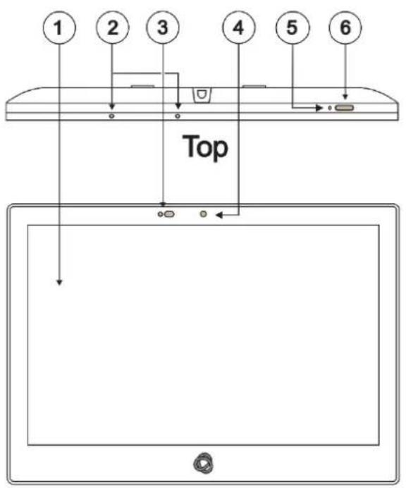
Front
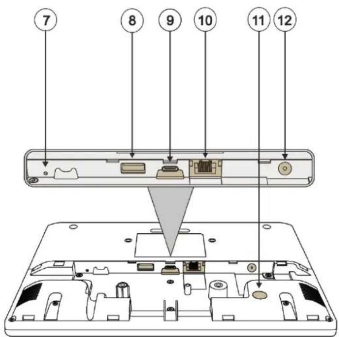
Back
Figure 1: KT-2015 / KT-2015WM 15" Touch Panel
| # | Feature | Function |
| 1 | Display | Touch panel |
| 2 | Microphone | For audio communication, recording or conferencing. |
| 3 | Proximity Sensor | Automatically adjusts the screen brightness and camera according to the room lighting conditions. |
| 4 | Camera | For future use. |
| 5 | Reset | Located on the topside. Insert a pin and hold for a few seconds to restart. |
| 6 | Home Button | Press to wake up / darken the screen. |
| 7 | Restore Factory Reset Button | Insert a pin and hold for 22 seconds to reset the device to factory default values. |
| 8 | USB 3.0 Port | Multipurpose port for external connection. |
| 9 | USB Type-C Port | Multipurpose port for external connection. |
| 10 | LAN 1G(PoE) RJ-45 Port | Connect to the LAN for network communication.KT-2015 / KT-2015WM are powered by PoE (power over ethernet) delivered through the LAN port.Optionally, you can connect the power adapter too (as backup). |
| 11 | Kensington Lock | Anti-theft security slot for locking the device. |
| 12 | 12V/2A DC Connector | Connect to the power adapter (optional, purchased separately). |
KT-2015 Tabletop Mount
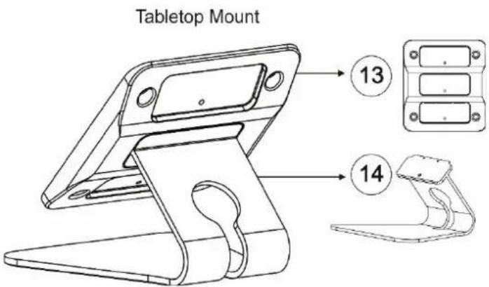
Figure 2: Tabletop Mount Rear View
| # | Feature | Function |
| 13 | VESA Bracket | A standard bracket for attaching the tablet to the stand. Use the large screw holes to secure the tablet and select one of the 3 small holes to secure the tablet to the stand (each hole creates a different angle). |
| 14 | Stand | Holds the VESA bracket. Has two screw holes, one to secure the VESA bracket and the other to (optionally) secure the stand to the table. |
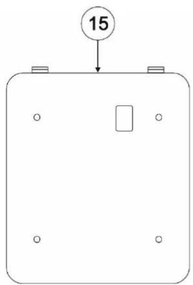
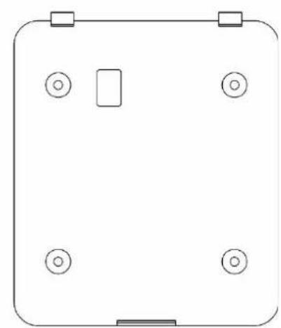
KT-2015WM On-Wall Mount
Front
natural_image
Simple line drawing of a rounded rectangle with four circular symbols at corners (no text or labels)Back
Figure 3: Wall mount bracket
| # | Feature | Function |
| 15 | Wall mount bracket | For securing the 15" Touch Panel to the wall mount bracket using the supplied M3 screw. For measurements see the image in Mounting KT-2015WM on a Wall on page 11. |
Mounting the KT-2015 / KT-2015WM
The KT-2015 package is for mounting the touch panel on a table and the KT-2015WM package is for mounting the touch panel on a wall.

Always be careful when attaching or removing the 15" Touch Panel from a mount.
Mounting KT-2015 on a Table
Mount KT-2015 on a table:
- Moveable Mount: Place the tabletop mount on the table. Connected cables remain visible and the table remains intact.
- Secure Mount: Bolt the tabletop mount into the table. Connected cables are hidden through a hole in the table.
1. Connect any cables.
Device will power on when PoE or DC is connected.
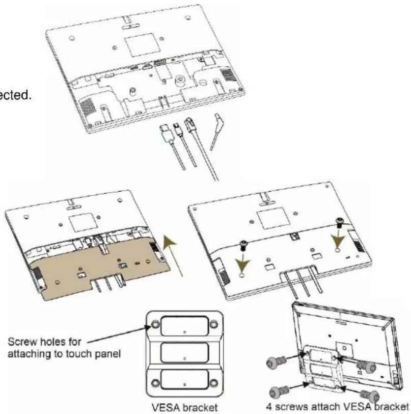
2. Install the I/O cover.
- Close with the M2*8 screws (qty 2).
3. Attach the VESA bracket.
- Lay the tablet face-down.
- Insert and tighten the 4 provided screws M4*8 (qty 4).
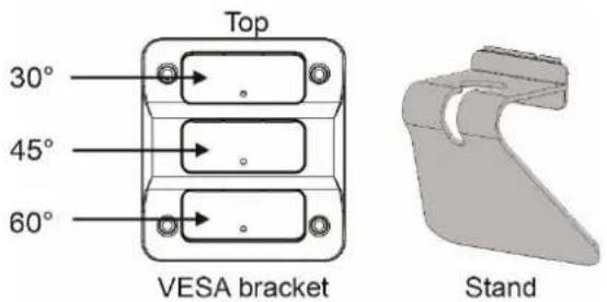
4. Insert the stand into the VESA bracket.
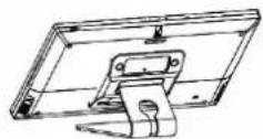
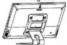
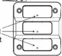
- The VESA bracket has 3 slots, each slot attaches the stand at a different angle: The top slot is 30^ , the middle 45^ and the bottom 60^ .
- Choose the slot you want to use (top, middle or bottom) and insert the stand.
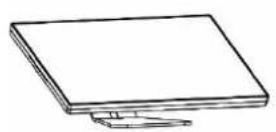
30 degrees
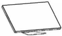
natural_image
Simple line drawing of a flat-screen computer monitor (no text or symbols)45 degrees
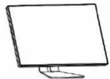
60 degrees
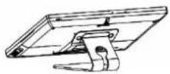
- Insert and tighten the 1 x M4*8 (qty 4) screw that secures the stand to the VESA bracket.
Screw holes for securing the stand to the selected slot
natural_image
Pure technical diagram of a mechanical component with three rectangular parts and directional arrows, no text or symbols present.VESA bracket
Optional: Mount the KT-2015 on the stand and secure it with the provided M3 screw.
The table stand and touch panel are now ready for use.

For optimum range and performance use the recommended Kramer cables available at https://www.kramerav.com/product/KT-2015 Using third-party cables may cause damage!
Mounting KT-2015WM on a Wall
Install KT-2015WM safely on a wall using a standard single Gang in-wall junction box. The cables are passed inside the wall and then connected to the rear side of the on-wall mount unit.
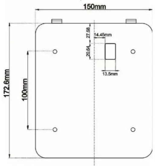
Figure 4: The on-wall mount's measurements.
Inserting the On-Wall Mount Unit
To mount the device on a one-gang box:

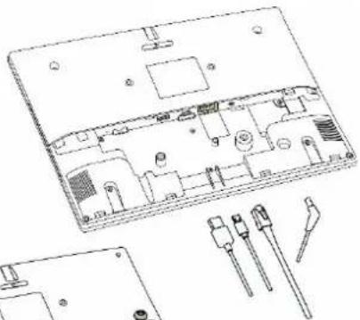
Important! Cables must be connected BEFORE mounting the touch pad on the wall.
- Connect any cables.
■ Device will power on when PoE or DC is connected.
natural_image
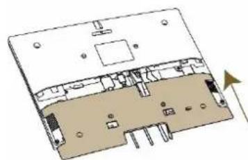
Technical line drawing of an electronic device interior with exploded view and component details (no text or symbols)- Install the I/O cover.
- Close with the M2*8 (qty 2) screws.
natural_image
Diagram of an electronic device interior showing internal components and a directional arrow (no text or labels)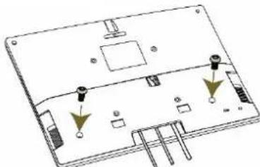
natural_image
Technical diagram of an electronic device casing with mounting points and internal components (no text or symbols)- Click the wall bracket onto the back of the I/O cover.
- Push the bracket into place while holding its top slightly outward.
Note: The bracket looks slightly different and has additional screw holes.
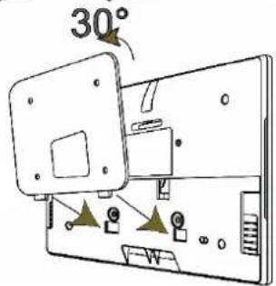
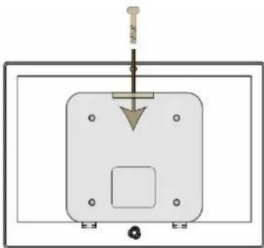
- Secure the wall bracket to the touch panel cover.
- Use the M3*15 (qty 1) screw.
To mount the device on a secured wall bracket:
-
Mount the wall bracket on to the installation point.
-
Screws not provided.
-
The bracket may have additional screw holes not shown here.
-
Connect the touch panel to the wall bracket.
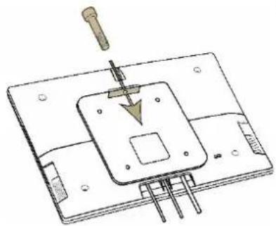
- Push the touch panel into place while holding its top slightly outward.
- Secure the touch panel to the wall bracket and back cover.
- Use the provided M3*15 (qty 1) screw.
natural_image
Technical line drawing of a mechanical assembly with a tool and component, no visible text or symbols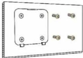
natural_image
Pure electrical circuit lines without any symbols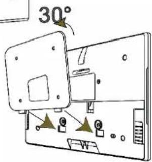
natural_image
Pure technical diagram of a mechanical assembly with no text, numbers, or symbols
For optimum range and performance use the recommended Kramer cables available at https://www.kramerav.com/product/KT-2015 Using third-party cables may cause damage!
Connecting Options
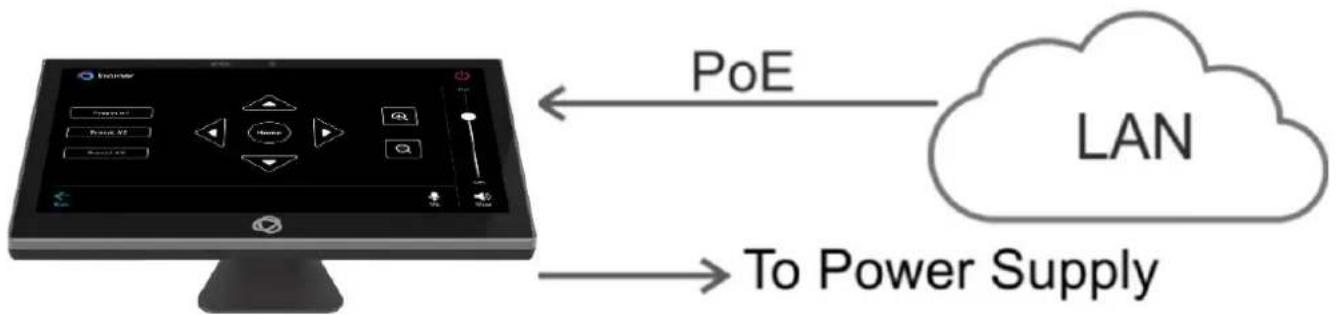
You can power the KT-2015 or KT-2015WM using any or all of the following options:
- Connect the PoE-enabled LAN RJ-45 connector to your local area PoE-enabled network.
- Connect the power adapter to the 12V DC connector on the rear side. The DC power supply is optional: It can be purchased separately.

When both PoE and the power supply are connected to the Touch Panel, the unit is powered by the power supply.
flowchart
graph LR
    A["Computer monitor with icons"] -->|PoE| B["LAN"]
    A -->|To Power Supply| B
Figure 5: Powering the Touch Panel
Controlling KT-2015 / KT-2015WM
Using Navigation Buttons or Gestures
By default, KT-2015 / KT-2015WM run the Kramer Control app and display its login screen at start-up. If available, you can use the navigation buttons displayed at the bottom of the screen. You can also set up your device to use gestures-based navigation.
Using navigation buttons
Swipe a finger upwards from the line at the bottom of the screen and release to see the navigation buttons:
- Back – Returns to the previous screen (or opens the home page if there is none).
- Home – Opens the home page, see Using the Home Page on page 15.
- Recent apps – Scroll between the active apps.
Changing the navigation system
By default, navigation buttons are used, however the touch panel can be set up to use navigation gestures instead. To change the navigation method:
- On the Home page, press Settings 📋. The device's Settings menu opens.
- Select Advanced settings > System.
- In the System menu, press Gestures and then System navigation.
- Select Gesture navigation or 3-button navigation. If you are using Gesture navigation, the sensitivity is adjustable.
Using Gesture navigation
- Back – Drag a finger inwards from the left or right edge of the screen.
- Home – Swipe a finger upwards from the line at the bottom of the screen and release.
- Recent apps – Swipe a finger upwards from the line at the bottom of the screen and hold.
Hiding the Navigation Bar
To hide/unhide the navigation bar:
- On the Home page, press the Settings button ⚙️. The device's Settings menu opens.
- In the Settings menu, open Player settings and enable Fullscreen mode.
Using the Home Page
Swipe a finger upwards from the Kramer icon at the bottom of the screen and release to see the navigation buttons. A PIN may be required (default 9428).
- Home – Opens the home page.
The Home page contains the following icons:

- Chromium browser

- Touch panel settings

Kramer Control agent
Exiting or Starting the Kramer Control app
KT-2015 / KT-2015WM come with a Kramer Control agent (icon 📋) pre-installed app. The role of this app is to display the interface you define in Kramer Control.
When the touch panel starts, the Kramer Control agent runs automatically. To exit the Kramer Control agent, enter the PIN (default 9428). If the PIN button is not displayed, swipe up from the Kramer icon at the bottom of the screen to bring up the PIN entry pop-up.
To re-open the Control Agent click the icon on the Home page.
During initial installation the k-agent app may need to be started manually the first time.
The Kramer Control agent can also be controlled by API calls. See Using the Kramer Agent's API on page 26.
Basic Settings of KT-2015 / KT-2015WM
Essential First Steps
To exit the Kramer Control agent, enter the PIN (default 9428). If the PIN button is not displayed, swipe up from the bottom of the screen to bring up the PIN entry pop-up.
To re-open the Control Agent click the 📄 on the Home page.
The following are essential first steps in using the touch panel:
- Set the device date and time; Setting the Date and Time on page 16.
- Setup the Ethernet and/or Wi-Fi connections; Connecting to Wi-Fi or Ethernet on page 17.
- Consider changing the time that the system checks for firmware (OS) updates; Changing the Automated Firmware Update on page 19. By default, this is set to midnight, change it if you have no internet access at midnight or prefer another time.
- Consider changing the time that the system checks for Kramer Control (APK) updates; Changing the Automated Kramer Control agent update on page 21. By default, this is set to midnight, change it if you have no internet access at midnight or prefer another time.
- Setup the Kramer Control agent's Launch URL; See Using the Kramer Control agent (connecting to Brain) on page 23.
- Change the display language (if necessary); Setting the Display and Keyboard Language on page 22.
Setting the Date and Time
The device arrives preset to New York time and you will need to set the correct time region.
To adjust the date and time settings:
- If necessary, swipe up from the bottom of the screen to bring up the PIN entry pop-up and enter the PIN (default 9428).
- On the Home page, press the Settings button ⚙️. The device's Settings menu opens.
- Select Date & Time > Time zone.
- Set the correct Region. The time will display correctly.
Connecting to Wi-Fi or Ethernet
Connect an Ethernet cable to the device or activate Wi-Fi and setup a connection to your Wi-Fi. If multiple network connections are used, Ethernet will be prioritized over any others.
If you are using 802.1X authentication, do Installing an 802.1X Certificate on page 18, before you connect to the internet.
Connecting Ethernet
Ethernet connections must be plugged into the back of the device, see ⑩ in Defining KT-2015 / KT-2015WM 15" Touch Panel on page 7. By default, the IP address of the device is set automatically by a DHCP server.
Enabling 802.1X authentication
- Do Installing an 802.1X Certificate on page 18.
- In the Settings screen, select Network & Internet > Ethernet.
- Make sure the Ethernet is disabled and then enable Security.

802.1X authentication cannot be applied to active Ethernet connections
- Select 802.1X settings and input the EAP (Extensible Authentication Protocol) information.
Using a static IP address
- If necessary, swipe up from the bottom of the screen to bring up the PIN entry pop-up and enter the PIN (default 9428).
- From the Home page, open the Settings screen
- In the Settings screen, select Network & Internet > Ethernet.
- Press Ethernet IP mode and select Static.
- Enter the IP information and press Connect.
The static IP address is setup.
Connecting Wi-Fi
Enabling 802.1X authentication
- Do Installing an 802.1X Certificate on page 18.
- From the Home page, open the Settings screen
- In the Settings screen, select Network & Internet > Wi-Fi.
- Make sure Use Wi-Fi is enabled. The device will scan and list the Wi-Fi networks.
- Select a Wi-Fi SSID, check Advanced options and enter the Wi-Fi information in the fields that appear, then press Connect.
- If you are using 802.1X authentication, then add the certificate information.
802.1X is enabled.

Installing an 802.1X Certificate
802.1X certificates enhance the security of network authentication. KT-2015 / KT-2015WM support .pem, .pfx and .p12 certificate formats.
Installing a certificate is a two-stage process: First import the certificate and then set it up.
Importing an 802.1X certificate
- Copy the certificate file to an empty USB flash drive.
- If necessary, swipe up from the bottom of the screen to bring up the PIN entry pop-up and enter the PIN (default 9428).
- From the Home page, open the Settings screen
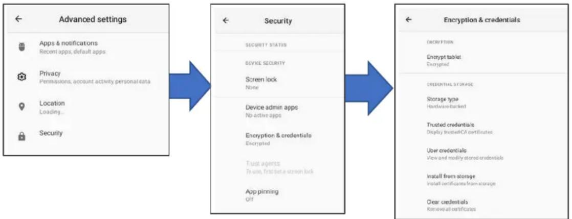
- Select Advanced settings > Security > Encryption & credentials.
flowchart
graph LR
    A["Advanced settings"] --> B["Security"]
    B --> C["Encryption & credentials"]

    subgraph Advanced settings
        A1["Apps & notifications\nRecent apps, default apps"]
        A2["Privacy\nPermissions, account activity personal data"]
        A3["Location\nLoading..."]
        A4["Security"]
    end

    subgraph Security
        B1["SECURITY STATUS"]
        B2["DEVICE SECURITY"]
        B3["Screen lock\nNone"]
        B4["Device admin apps\nNo active apps"]
        B5["Encryption & credentials\nEncrypted"]
        B6["Trust agents\nTo use, first set a screen lock"]
        B7["App pinning\nOFF"]
    end

    subgraph Encryption & credentials
        C1["ENCRYPTION"]
        C2["Encrypt tablet\nEncrypted"]
        C3["CREDENTIAL STORAGE"]
        C4["Storage type\nHardware-backed"]
        C5["Trusted credentials\nDisplay treated CA certificates"]
        C6["User credentials\nView and modify stored credentials"]
        C7["Install from storage\nInstall certificates from storage"]
        C8["Clear credentials\nRemove all certificates"]
    end
Figure 6: The path to Install from storage
- In the Encryption & credentials screen, select Install from storage: The Install a certificate screen opens.
- Select the Wi-Fi certificate: The Recent files screen opens. To browse to the file location, press the 3 lines at the top left of the screen.
- Select the credentials file and install it, some certificates require you to know a password.
Setting up an 802.1X certificate
- In the Settings screen, select Network & Internet > Wi-Fi.
- Select Install from storage: The Install a certificate screen opens.
- Select Wi-Fi certificate (also for Ethernet connections): The Recent files screen opens. To browse to the file location, press the 3 lines at the top left of the screen.
After installing the certificates, see Connecting to Wi-Fi or Ethernet on page 17 for instructions on using the certificates. Ethernet must be disabled before setting-up Ethernet certificates.
Changing the Automated Firmware Update
KT-2015 / KT-2015WM arrive preset to check for firmware (touch panel OS) updates at midnight every day. If an update is found, the device will download the update file and install it. If you prefer to run manual updates, you must manually download the update file and then install it in the touch panel.
Changing the time of the automated firmware check
- If necessary, swipe up from the bottom of the screen to bring up the PIN entry pop-up and enter the PIN (default 9428).
- From the Home page, open the Settings screen
- Select Firmware update and then select Remote firmware upgrade URL.
Remote firmware upgrade URL is the site from which the firmware is downloaded.
The upgrade URL (case sensitive):
https://cdn.kramerav.com/web/apk/transformer-Kramer-AndroidR.xml
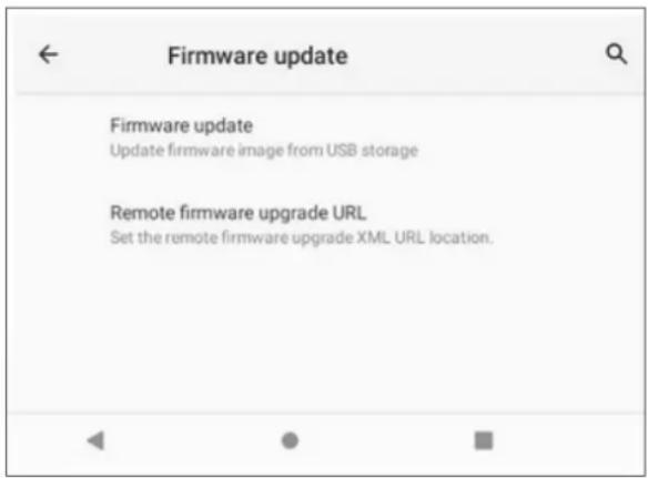
Figure 7: The Firmware update page
- A pop-up opens, inviting you to set the check time:
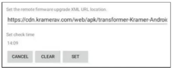
Figure 8: The Remote firmware upgrade URL page
- To change the time that the system checks for updates, press Set check time and select a new time.
- Press OK to close the window and then press SET.

Changing (or clearing) the URL will disable the updates.
Manually updating the firmware
Manual firmware updates require a downloaded firmware file from Kramer.
The firmware upgrade process requires:
- An empty USB flash drive to store the firmware file.
- A micro-USB OTG (on the go) cable to connect the USB flash drive to the touch panel.
- Access to the back of the touch panel.
You may need to remove the touch panel from its mount for this purpose. The touch panel should remain connected to a power source such as PoE or the optional power adapter (see 12 in Defining KT-2015 / KT-2015WM 15" Touch Panel on page 7).
To upgrade the firmware
-
Download the firmware update file from the Kramer website at www.kramerav.com/product/KT-2015.
-
Verify that you are using the correct KT-2015 / KT-2015WM firmware file as there maybe more than one firmware file available.
-
Do not unzip the firmware update file.
-
Copy the firmware file to an empty USB flash drive.
- If necessary, swipe up from the bottom of the screen to bring up the PIN entry pop-up and enter the PIN (default 9428).
- On the touch panel, open the Settings screen
- Select Firmware update and then select Firmware update (again).
- Plug the USB flash drive into a micro-USB OTG cable and connect the cable to the back of the touch panel.
- Click START FIRMWARE UPDATE.
The firmware update will then begin.
Changing the Automated Kramer Control agent update
KT-2015 / KT-2015WM arrive preset to check for Kramer APK (Android Application Package) updates at midnight every day. If an update is found, the device will download the update file and install it.
Changing the time of the automated APK update check
-
If necessary, swipe up from the bottom of the screen to bring up the PIN entry pop-up and enter the PIN (default 9428).
-
From the Home page, open the Settings screen

- Select Remote APP upgrade URL.
Remote APP upgrade URL is the site from which the APK is downloaded.
The upgrade URL (case sensitive) is: https://cdn.kramerav.com/web/apk/remote_app_update.xml
- A pop-up opens, inviting you to set the check time:
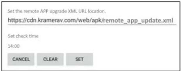
Figure 9: The Remote APP upgrade URL page
-
Press Set check time to select a new time.
-
Press OK to close the window and then press SET.

Changing (or clearing) the URL will disable the updates.
Setting the Display and Keyboard Language
To set your preferred interface language:
- If necessary, swipe up from the bottom of the screen to bring up the PIN entry pop-up and enter the PIN (default 9428).
- From the Home page, open the Settings screen
- Select Language & input.
- Press Add a language to select a language.
- If you are using multiple languages, the order in which they are listed represents the priority assigned to them, change the order by dragging languages.
- Press On-screen keyboard to select keyboard languages.

The keyboard language has been set.
Using the Kramer Control agent (connecting to Brain)
The KT-2015 / KT-2015WM touch panel contains a Kramer Control agent (an app), that downloads and displays a user-designed customized interface from Kramer Control Brain.
The customized interface can control all aspects of the meeting space. For more information about Kramer Brain, see www.kramerav.com/product/KT-2015.
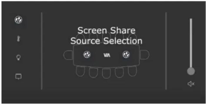
Figure 10: Example of a touch panel interface menu
When the touch panel starts, the Kramer Control agent runs automatically (it is pre-installed on KT-2015 / KT-2015WM). If an interface has been defined, it will be displayed. If not, it will display the Kramer Agent welcome screen where you can enter the interface's IP.
Entering the Control Interface IP & Port Number
On the first run, the Kramer Control app requests the IP & port number of the customized Brain interface to be displayed. The hardware section of the builder's Brain Info contains the URL (in the format IP:port#) of the customized Brain interface. If more than one interface is defined in the Brain, the Brain's IP and port must be followed by two parameters: /?Interface=
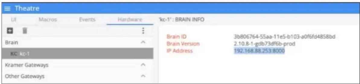
Figure 11: Interface IP Address
Kramer Control Brain port numbers
The IP and port number (and a code on SL-240 / SL-280) are entered in the format IP:port#.
- Kramer SL-240 or SL-280: Port 8000.
- KC-Virtual Brain 1: Port 8001.
- KC-Virtual Brain 5: Ports 8001 - 8005 (KC-Virtual Brain 5 can define up to 5 different touch pad control interfaces, each will use a different port).
The Kramer Control Agent Settings
By default, the Kramer Agent's Welcome screen (Settings) appears the first time the touch panel runs.

To open the Settings:
Slide your finger from the top to the bottom of the screen or vice versa.
The Kramer Agent has 3 settings:
- Control Interface
- Display Policy
- Lock Tablet
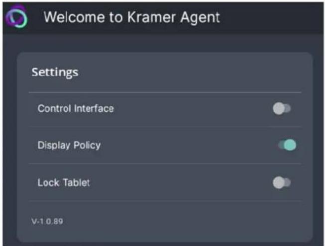
Figure 12: Kramer Agent Welcome screen
- Press each setting to see more options (described below).
- Use the sliders to enable/disable a setting.
- These settings can also be set by API calls. See Using the Kramer Agent's API on page 26.
1. Control Interface
Press Control Interface to set the interface IP and Immersive mode.
- Control Interface (slider) After entering the IP of the Control Interface, move the slider to activate the interface and exit the pop-up.
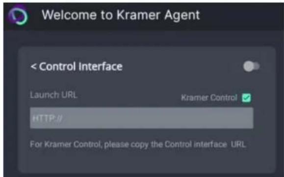
Figure 13: Control Interface options
- Launch URL Enter the IP of the Control Interface or a webpage URL you want displayed on the touch panel. For more options see Methods of Setting the Control Interface IP on page 28.
- Kramer Control (check box) By default, the Kramer Control box is checked, setting the tablet in Immersive Mode: In Immersive (full screen) mode, the system bars are hidden, and users must swipe up/down and enter a PIN to exit the Control Interface. If you are using a generic webpage (such as www.google.com), Immersive mode must be disabled.
2. Display Policy
Press Display Policy to view more options.
- Display Policy (slider) Move the slider to activate the policy.
- Set Default Brightness Level This is the % of maximum brightness that the touch panel will return to when the display is re-activated.
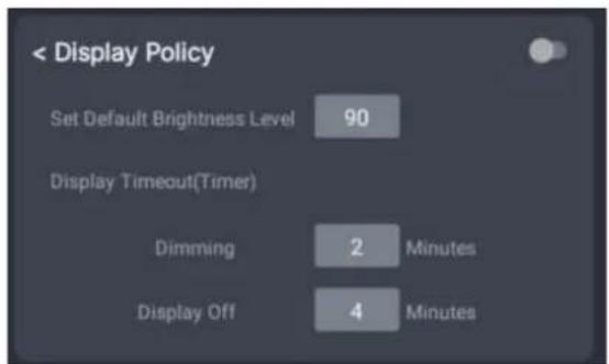
Figure 14: Display Policy options
• Display Timeout (Timer)
Dimming – The minutes of inactivity, before dimming to 20% of maximum brightness. Display Off – The minutes of inactivity, before switching off the display (must be longer than the dimming timeout).
3. Lock Tablet (and USB)
Enable/disable the PIN that restricts access to the Kramer Control agent and USB. Press Lock Tablet to change the PIN and view more options. USB locking is optional.
- Lock Tablet (slider)
Move the slider to activate the locking policy defined below.
• PIN to Unlock screen
9428 is the default value. Enter a new PIN to change the value.
- USB Lock – Check this box for the tablet lock policy to also disable the tablet's USB port.
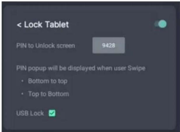
Figure 15: Lock Tablet options
Using the Kramer Control Agent's API
The API changes Kramer Control agent settings remotely, without using the touch panel.

Note:
- The touch panel must be switched on and connected to the same LAN.
- If more than one interface is defined in the Brain, the Brain's IP and port must be followed by two parameters: /?Interface=
&page= . See example 2 below.
Example: Setting the Launch URL in the Control Agent
a) Open a browser window on a computer connected to the same network as the touch panel.
b) Example: To set the Launch URL in the Kramer Control agent (on the touch panel), use the following format:
https://
Example 1 (single interface defined in Brain):
If the touch panel IP is "192.168.0.56" and the Brain interface IP is "192.168.22.53:8001", enter https://192.168.0.56:9804/launchkramerurl?192.168.22.53:8001
Example 2 (multiple interfaces defined in Brain):
The URL must include the full interface ID and page. Touch panel IP is "192.168.0.56" and the Brain interface IP is "192.168.2.53:8001/?interface=e84f5fb8-c5a3-4675-9006-d79d3e6cfe59&page=5913c07a-9a41-4fac-9870-e87b1ef719df".
Enter
https://192.168.0.56:9804/launchkramerurl?192.168.2.53:8001/?interface=e84f5fb8-c5a3-4675-9006-d79d3e6cfe59&page=5913c07a-9a41-4fac-9870-e87b1ef719df
Note: Use port 9803 if the touch panel uses http and port 9804 if it uses https.
After this command is sent, the touch panel will display the Brain-defined interface.
See the next page for a full list of API commands.
The following API commands can be sent to the touch panel from a browser:
| Function | Command structure | Status response (in browser) |
| Check if the Control agent is running | https://:9804/health/ | “up” |
| Reboot the touch panel | https://:9804/reboot/ | “Rebooting” |
| Pause the Control Interface and return to k-agent settings | https://:9804/pauselaunchautourl/ | “URL launched is paused, Move to Main View” |
| Resume the Control Interface | https://:9804/resumelaunchautourl/ | “URL launched is resumed” |
| Clear the Control Interface's URL setting | https://:9804/reseturl/ | “URL is reset now” |
| Set the Control Interface URL (immersive mode).* | https://:9804/launchkramerurl?:: | “Browser will be launched with given URL.” |
| Define a generic URL (touch panel display a non-Brain URL such as www.google.com | https://:9804/launchurl?: | “Browser will be launched with given URL.” |
| Enable/disable display control | https://:9804/displaysettingon (or displaysettingoff) | |
| Set the timeout to turn off the display after 4 minutes inactivity | https://:9804/setdisplayofftimevalue=4 | |
| Set the timeout to dim the display after 2 minutes inactivity | https://:9804/setdisplaydimtime=2 | |
| Set the display brightness in % | https://:9804/setdisplaybrightnessvalue=100 |
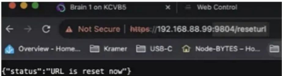
Figure 16: Example of a successful response message.
* If more than one interface is defined in the Brain, the Brain's IP and port must be followed by two parameters: /?Interface=
For example:
https://192.168.0.56:9804/launchkramerurl?192.168.2.53:8001/?interface=e84f5fb8-c5a3-4675-9006-d79d3e6cfe59&page=5913c07a-9a41-4fac-9870-e87b1ef719df
Methods of Setting the Control Interface URL
When the touch panel starts, the (pre-installed) Kramer Control agent runs automatically. You will need to set up its connection with the Kramer Brain, so that it can display the desired control interface.
There are 3 possible methods of setting the interface IP in the Kramer Control agent:
- In the Kramer Control agent (on the touch panel screen).
- Using the API (on a remote computer connected to the same network).
- In the Brain software (setting up the touch panel in the Brain software).
Any one of these methods can load the interface URL into the touch panel's Kramer Control agent.
1. Entering the interface IP in the Kramer Control agent
a. Kramer Control agent opens automatically when the touch panel starts. If no interface IP has been entered, the Kramer Agent's Welcome screen is displayed:
- If the touch panel is not displaying the Welcome screen, open the Kramer Agent app from the touch panel's Home page and it will be displayed.
b. Press Control Interface; the Launch URL pop-up appears.
c. Enter the IP address and port of the interface that was defined in Kramer Brain, for example https://192.168.88.180:8001.
If more than one interface is defined in the Brain, the Brain's IP and port must be followed by two parameters: /?Interface=
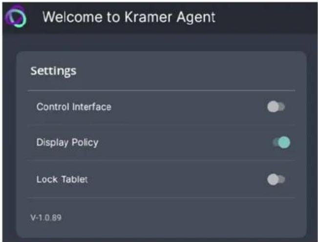
Figure 17: The Kramer Agent Welcome screen
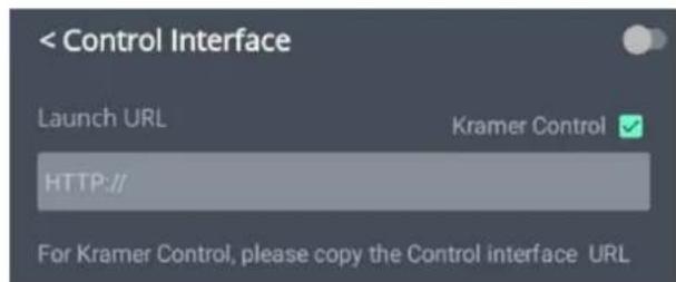
Figure 18: The Launch URL pop-up
See also Finding the Control Interface IP on page 23 and Example of Setting the Launch URL on page 26.
d. By default, the Kramer Control box is checked, setting the tablet in Immersive Mode: In Immersive (full screen) mode, the system bars are hidden, and users can only exit the interface by swiping up and entering a PIN. Immersive mode is recommended for the Kramer Control interface; Disable it if you are using a generic webpage (such as www.google.com).
e. Press OK and the touch panel will load your interface.
f. To exit the Control Interface and access touch panel controls, slide your fingers up from the bottom of the screen and enter the PIN (default 9428).
2. Controlling the Kramer Control agent by API call
This method of changing settings of the Kramer Control interface can be done remotely, without using the touch panel.
For more information see Using the Kramer Control Agent's API on page 26.
Note: The touch panel must be switched on and connected to the same LAN.
a) Open a browser window on a computer connected to the same network as the touch panel.
b) To set the IP of the Control Interface displayed by the Call the touch panel in the following format:
https://
• Example 1 (single interface defined in Brain):
If the touch panel IP is "192.168.0.56" and the Brain interface IP is "192.168.22.53:8001", enter https://192.168.0.56:9804/launchkramerurl?192.168.22.53:8001
• Example 2 (multiple interfaces defined in Brain):
The URL must include the full interface ID and page. Touch panel IP is "192.168.0.56" and the Brain interface IP is "192.168.2.53:8001/?interface=e84f5fb8-c5a3-4675-9006-d79d3e6cfe59&page=5913c07a-9a41-4fac-9870-e87b1ef719df".
Enter
https://192.168.0.56:9804/launchkramerurl?192.168.2.53:8001/?interface=e84f5fb8-c5a3-4675-9006-d79d3e6cfe59&page=5913c07a-9a41-4fac-9870-e87b1ef719df
After this command is sent, the touch pad will display the Brain-defined interface and a status response message returned to the sender.
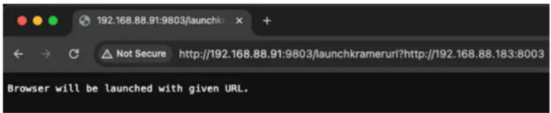
Figure 19: Example of a successful response message.
3. Setup the touch panel in the Brain Builder
The advantage of this method is that future changes to the interface are automatically uploaded to the tablet.
The following assumes that:
a) The interface is already setup in the Brain.
b) The touch panel is active and connected to the same network as the Brain.
c) The IP of the touch panel is static and DHCP assigned.
- Preliminary Setup: In the Devices tab of the Builder screen, add the K-Agent driver as a device. It must be assigned to the same network gateway as the touch panel.
- Navigate to the Brain control page on your computer.
- Select the interface that you want to use on the touch panel.
- Copy the interface's URL from the address bar (see the image below).

- Navigate back to the Builder, double click on the touch panel (in the Devices list) and paste the URL from the previous step to the Kramer Control URL. Assign it a Friendly Name.
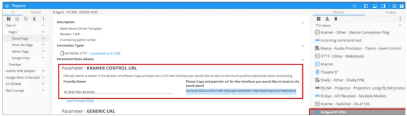
Figure 20: Kramer Control URL in the Builder
- For the Brain to be able to automatically assign the user interface to the touch panel:
(see the image on the next page)
a) In the Events tab, click System Events and select "Initialization".
b) Drag the Launch Kramer URL command to the 'Initialization' ACTIONS area.
c) Select the Friendly Name (If only one interface is defined, it will be used by default).
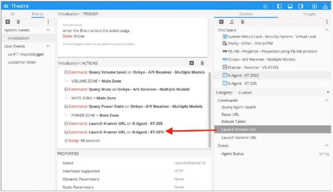
Figure 21: System Events window open on Initialization actions
- Every time the Brain reboots or connects to the touch panel the interface will be updated.
Advanced Settings
Scheduling a Daily Reboot
A daily reboot is recommended to improve product performance and stability. The daily reboot option causes the device to reset itself every day and the set time (or within 30 minutes of the set time if it is in use).
- If necessary, swipe up from the bottom of the screen to bring up the PIN entry pop-up and enter the PIN (default 9428).
- From the Home page, open the Settings screen
- Select Schedule Reboot and set the reboot time.
- Enable Optimize Server Performance to have the device reboot at a random time within 30 minutes of the scheduled time. If you are using multiple devices, then this prevents them from all rebooting at the same time.
The daily reboot is complete.
Password Protecting Device Settings
Device settings can be protected with a password to prevent users from making any changes.
- If necessary, swipe up from the bottom of the screen to bring up the PIN entry pop-up and enter the PIN (default 9428).
- From the Home page, open the Settings screen
- Select Security Password to enable and enter the password.
Factory Reset & Reboot
The Settings > Reset options menu enables you to perform a factory reset or to reboot the device, reset Wi-Fi or Bluetooth or reset app preferences.
To reset to factory settings
- If necessary, swipe up from the bottom of the screen to bring up the PIN entry pop-up and enter the PIN (default 9428).
- From the Home page, open the Settings screen
- Select Erase all data (factory reset).
Other options available: Reboot device, Reset Wi-Fi, mobile & Bluetooth and Reset app preferences.
Resetting with the external reset button
Insert a pin into the pinhole on the back (see ⑦ in Defining KT-2015 / KT-2015WM 15" Touch Panel on page 7) and hold for 22 seconds to reset the device to factory default values.
A second pinhole on the top, ⑤ can be used to restart the device by inserting a pin for a few seconds.
Logging Activity
By default, the device does not log activity. Logging can be useful for debugging or monitoring use.
Activating logging
- From the Home page, open the Settings screen
- Select Log and set the Log Location.
Logging is activated.

Accessing an internally stored log file
A USB flash drive and OTG cable are required to copy an internally stored log file:
- In the root directory of the flash drive, create a folder called “_dump_debug_log”.
- Connect the OTG cable to the micro-USB connection on the back of the device.
- Connect the flash drive to the OTG cable.
- The device will automatically download the log file to the USB device and issue a confirmation message "Saved log file to USB storage".
The log is accessed.
Defining an auto-start playlist
The device can be set to automatically play the contents of a predefined folder. The folder can be internally defined or read from a flash device connected to the micro USB port or a Micro SD card inserted into the card reader (see Defining KT-2015 / KT-2015WM 15" Touch Panel on page 7).
To setup a playlist:
- Load the media you want to play onto an SD card or USB flash drive. Play order is set by the alphabetic order of the item's names.
- Connect the drive or card to the device (for a flash drive use an OTG cable connected to the USB port).
- If necessary, swipe up from the bottom of the screen to bring up the PIN entry pop-up and enter the PIN (default 9428).
- On the touch panel, open the Settings screen
- Select Player Settings and then select Instant Play.
- Enable Instant play. If you check Copy and play as internal storage, the device will load the (external) folder contents into internal storage.
- Press SELECT FOLDER.
- If you copied external content to internal storage, then you can remove the external device.

The Content field in the Home page will be changed to the storage location of your content.

The home page's Content field defines the auto-start link to Kramer Control.
Changing the value in this field is not recommended as it will disable Kramer Control.
Defining auto-start HTML or SMIL content
The device home page can be set to automatically run an HTML page or Synchronized Multimedia Integration Language (SMIL) content.
- Place your HTML content in a folder called HTML in the root of an SD card or flash drive and attach them to the device (for a flash drive use an OTG cable connected to the USB port).
- When the USB drive is connected to the device, an automatic pop-up message will notify you that the copy is about to start.
The Content field in the Home page will be changed to the storage location of your content.

The home page's Content field defines the auto-start link to Kramer Control.
Changing the value in this field is not recommended as it will disable Kramer Control.
Modifying Display Settings
The screen orientation can be customized, and the navigation bar can be hidden.
Changing the screen orientation
- If necessary, swipe up from the bottom of the screen to bring up the PIN entry pop-up and enter the PIN (default 9428).
- From the Home page, open the Settings screen
- Select Display and then press Screen Orientation.
Choose between 0 degrees (default), 90 degrees, 180 degrees and 270 degrees.
Hiding the navigation bar
- If necessary, swipe up from the bottom of the screen to bring up the PIN entry pop-up and enter the PIN (default 9428).
- From the Home page, open the Settings screen
- In the Settings menu, open Player settings and enable Fullscreen mode.
The Navigation bar is no longer accessible.
Switching to Native Android Mode
Switching to native Android mode turns the device into a regular android device, allowing you full control of its content.

Changing to native Android will disable Kramer Control.
To make the switch:
- If necessary, swipe up from the bottom of the screen to bring up the PIN entry pop-up and enter the PIN (default 9428).
- From the Home page, open the Settings screen
- Select Player Settings and then press Native Android Mode.
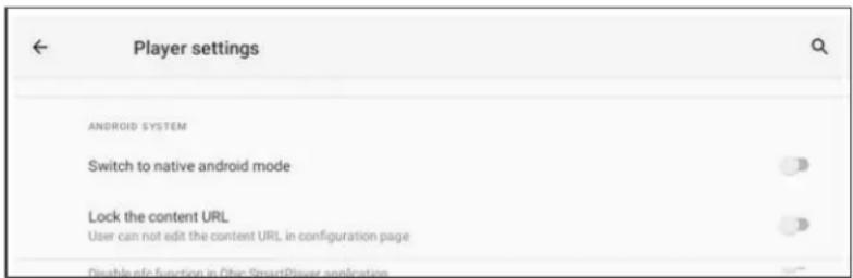
Figure 22: The Player settings page
Native Android mode is restored.
Technical Specifications
| Ports | 1 USB Type C | On a female (ADB) connector |
| 1 USB Type A | On a female connector | |
| 1 Ethernet | On an RJ-45 female connector, 10/100/1000M with PoE 802.3at | |
| Platform | Operating System | Android Version 11 |
| CPU | ARM Quad Core Cortex-A53 up to 1.8Ghz (64 bit) | |
| Memory | RAM | LPDDR4 4GB |
| Internal | 32GB eMMC (flash) | |
| Display | Touch Panel Type | Capacitive multi-touch |
| Size | 15" | |
| Resolution | 1920x1080 RGB pixels, 16:9 aspect ratio, 350cd/m2 brightness, 1000:1 contrast ratio | |
| Wireless Connectivity | Wi-Fi | Wi-Fi 6, 802.11 a/b/g/n/ax |
| Bluetooth | BT 5.0 | |
| Video | Camera | 1x 5MP FF |
| Video Formats | H.264, H.265, VC-1, MPEG-4, VP8, VP9 | |
| Image Codecs | JPEG, BMP, GIF, PNG | |
| VESA | Metal-fittings mounting screw holes for 75x75mm VESA mount | |
| Audio | Speakers | 2 built-in x 1W |
| Codecs | MPEG, OGG, AAC | |
| Microphone | 2 built-in | |
| Power | PoE | 44 to 57V DC 0.6A complies with IEEE802.3af and IEEE802.3at PoE standards |
| Optional power adapter | 12V DC 3ANote: Operating Temperature: 0~40°C | |
| Controls | Function button | On top |
| Reset button | On top, recessed | |
| Factory reset button | On back, recessed | |
| LED | Sidelight | Can indicate room status (requires 3^rd party integration) |
| Environmental conditions | Operating temperature | 0~40°C (32~104°F) |
| Storage temperature | -20~60°C (-4° to 140°F) | |
| Operating Humidity | 5% to 85% | |
| Storage Humidity | 5% to 90% | |
| Regulatory Compliance | Safety | CE, FCC, UL, UKCA |
| Environmental | RoHs, WEEE | |
| Dimensions | Touch panel (W, D, H) | 26.2 x 373.5 x 243.1mm |
| Touch panel tabletop stand | 162 x 146 x 145mm (KT-2015 only) | |
| Wall mount | 172.6 x 150 x 4mm (KT-2015WM only)See the image in Mounting KT-2015WM on a Wall on page 11. | |
| Weight | Touch panel | 1.78kg |
| Touch tabletop stand | 300g | |
| Shipping carton (4 pcs) | Dimensions (W, D, H) | 600 x 492 x 356mm |
| Weight | KT-2015: 2.83kg (approximate)KT-2015WM: 2.66kg (approximate) | |
| Accessories | Optional | Power adapter. |
| KT-2015 | Table-top mount and screws. | |
| KT-2015WM | On-wall mount bracket and screws. | |
| Specifications are subject to change without notice at www.kramerav.com | ||
The warranty obligations of Kramer Electronics Inc. ("Kramer Electronics") for this product are limited to the terms set forth below:
What is Covered
This limited warranty covers defects in materials and workmanship in this product.
What is Not Covered
This limited warranty does not cover any damage, deterioration or malfunction resulting from any alteration, modification, improper or unreasonable use or maintenance, misuse, abuse, accident, neglect, exposure to excess moisture, fire, improper packing and shipping (such claims must be presented to the carrier), lightning, power surges, or other acts of nature. This limited warranty does not cover any damage, deterioration or malfunction resulting from the installation or removal of this product from any installation, any unauthorized tampering with this product, any repairs attempted by anyone unauthorized by Kramer Electronics to make such repairs, or any other cause which does not relate directly to a defect in materials and/or workmanship of this product. This limited warranty does not cover cartons, equipment enclosures, cables or accessories used in conjunction with this product.
Without limiting any other exclusion herein, Kramer Electronics does not warrant that the product covered hereby, including, without limitation, the technology and/or integrated circuit(s) included in the product, will not become obsolete or that such items are or will remain compatible with any other product or technology with which the product may be used.
How Long this Coverage Lasts
The standard limited warranty for Kramer products is seven (7) years from the date of original purchase, with the following exceptions:
- All Kramer VIA hardware products are covered by a standard three (3) year warranty for the VIA hardware and a standard three (3) year warranty for firmware and software updates; all Kramer VIA accessories, adapters, tags, and dongles are covered by a standard one (1) year warranty.
- Kramer fiber optic cables, adapter-size fiber optic extenders, pluggable optical modules, active cables, cable retractors, ring mounted adapters, portable power chargers, Kramer speakers, and Kramer touch panels are covered by a standard one (1) year warranty. Kramer 7-inch touch panels purchased on or after April 1st, 2020 are covered by a standard two (2) year warranty.
- All Kramer Calibre products, all Kramer Minicom digital signage products, all HighSecLabs products, all streaming, and all wireless products are covered by a standard three (3) year warranty.
- All Sierra Video MultiViewers are covered by a standard five (5) year warranty.
- Sierra switchers & control panels are covered by a standard seven (7) year warranty (excluding power supplies and fans that are covered for three (3) years).
- K-Touch software is covered by a standard one (1) year warranty for software updates.
- All Kramer passive cables are covered by a lifetime warranty.
Who is Covered
Only the original purchaser of this product is covered under this limited warranty. This limited warranty is not transferable to subsequent purchasers or owners of this product.
What Kramer Electronics Will Do
Kramer Electronics will, at its sole option, provide one of the following three remedies to whatever extent it shall deem necessary to satisfy a proper claim under this limited warranty:
- Elect to repair or facilitate the repair of any defective parts within a reasonable period of time, free of any charge for the necessary parts and labor to complete the repair and restore this product to its proper operating condition. Kramer Electronics will also pay the shipping costs necessary to return this product once the repair is complete.
- Replace this product with a direct replacement or with a similar product deemed by Kramer Electronics to perform substantially the same function as the original product. If a direct or similar replacement product is supplied, the original product's end warranty date remains unchanged and is transferred to the replacement product.
- Issue a refund of the original purchase price less depreciation to be determined based on the age of the product at the time remedy is sought under this limited warranty.
What Kramer Electronics Will Not Do Under This Limited Warranty
If this product is returned to Kramer Electronics or the authorized dealer from which it was purchased or any other party authorized to repair Kramer Electronics products, this product must be insured during shipment, with the insurance and shipping charges prepaid by you. If this product is returned uninsured, you assume all risks of loss or damage during shipment. Kramer Electronics will not be responsible for any costs related to the removal or re-installation of this product from or into any installation. Kramer Electronics will not be responsible for any costs related to any setting up this product, any adjustment of user controls or any programming required for a specific installation of this product.
How to Obtain a Remedy Under This Limited Warranty
To obtain a remedy under this limited warranty, you must contact either the authorized Kramer Electronics reseller from whom you purchased this product or the Kramer Electronics office nearest you. For a list of authorized Kramer Electronics resellers and/or Kramer Electronics authorized service providers, visit our web site at www.kramerav.com or contact the Kramer Electronics office nearest you.
In order to pursue any remedy under this limited warranty, you must possess an original, dated receipt as proof of purchase from an authorized Kramer Electronics reseller. If this product is returned under this limited warranty, a return authorization number, obtained from Kramer Electronics, will be required (RMA number). You may also be directed to an authorized reseller or a person authorized by Kramer Electronics to repair the product.
If it is decided that this product should be returned directly to Kramer Electronics, this product should be properly packed, preferably in the original carton, for shipping. Cartons not bearing a return authorization number will be refused.
Limitation of Liability
THE MAXIMUM LIABILITY OF KRAMER ELECTRONICS UNDER THIS LIMITED WARRANTY SHALL NOT EXCEED THE ACTUAL PURCHASE PRICE PAID FOR THE PRODUCT. TO THE MAXIMUM EXTENT PERMITTED BY LAW, KRAMER ELECTRONICS IS NOT RESPONSIBLE FOR DIRECT, SPECIAL, INCIDENTAL OR CONSEQUENTIAL DAMAGES RESULTING FROM ANY BREACH OF WARRANTY OR CONDITION, OR UNDER ANY OTHER LEGAL THEORY. Some countries, districts or states do not allow the exclusion or limitation of relief, special, incidental, consequential or indirect damages, or the limitation of liability to specified amounts, so the above limitations or exclusions may not apply to you.
Exclusive Remedy
TO THE MAXIMUM EXTENT PERMITTED BY LAW, THIS LIMITED WARRANTY AND THE REMEDIES SET FORTH ABOVE ARE EXCLUSIVE AND IN LIEU OF ALL OTHER WARRANTIES, REMEDIES AND CONDITIONS, WHETHER ORAL OR WRITTEN, EXPRESS OR IMPLIED. TO THE MAXIMUM EXTENT PERMITTED BY LAW, KRAMER ELECTRONICS SPECIFICALLY DISCLAIMS ANY AND ALL IMPLIED WARRANTIES, INCLUDING, WITHOUT LIMITATION, WARRANTIES OF MERCHANTABILITY AND FITNESS FOR A PARTICULAR PURPOSE. IF KRAMER ELECTRONICS CANNOT LAWFULLY DISCLAIM OR EXCLUDE IMPLIED WARRANTIES UNDER APPLICABLE LAW, THEN ALL IMPLIED WARRANTIES COVERING THIS PRODUCT, INCLUDING WARRANTIES OF MERCHANTABILITY AND FITNESS FOR A PARTICULAR PURPOSE, SHALL APPLY TO THIS PRODUCT AS PROVIDED UNDER APPLICABLE LAW. IF ANY PRODUCT TO WHICH THIS LIMITED WARRANTY APPLIES IS A "CONSUMER PRODUCT" UNDER THE MAGNUSON-MOSS WARRANTY ACT (15 U.S.C.A. §2301, ET SEQ.) OR OTHER APPLICABLE LAW, THE FOREGOING DISCLAIMER OF IMPLIED WARRANTIES SHALL NOT APPLY TO YOU, AND ALL IMPLIED WARRANTIES ON THIS PRODUCT, INCLUDING WARRANTIES OF MERCHANTABILITY AND FITNESS FOR THE PARTICULAR PURPOSE, SHALL APPLY AS PROVIDED UNDER APPLICABLE LAW.
Other Conditions
This limited warranty gives you specific legal rights, and you may have other rights which vary from country to country or state to state.
This limited warranty is void if (i) the label bearing the serial number of this product has been removed or defaced, (ii) the product is not distributed by Kramer Electronics or (iii) this product is not purchased from an authorized Kramer Electronics reseller. If you are unsure whether a reseller is an authorized Kramer Electronics reseller, visit our web site at www.kramerav.com or contact a Kramer Electronics office from the list at the end of this document. Your rights under this limited warranty are not diminished if you do not complete and return the product registration form or complete and submit the online product registration form. Kramer Electronics thanks you for purchasing a Kramer Electronics product. We hope it will give you years of satisfaction.

HDMI™
HIGH-DEFINITION MULTIMEDIA INTERFACE

P/N: 2900-301732

Rev:


SAFETY WARNING
Disconnect the unit from the power supply before opening and servicing
For the latest information on our products and a list of Kramer distributors, visit our website where updates to this user manual may be found.
We welcome your questions, comments, and feedback.
The terms HDMI, HDMI High-Definition Multimedia Interface, and the HDMI Logo are trademarks or registered trademarks of HDMI Licensing Administrator, Inc. All brand names, product names, and trademarks are the property of their respective owners.
- Contents
- Contents 2
- Introduction 3
- Defining KT-2015 / KT-2015WM 15" Touch Panel 7
- Mounting the KT-2015 / KT-2015WM 9
- Controlling KT-2015 / KT-2015WM 14
- Basic Settings of KT-2015 / KT-2015WM 16
- Using the Kramer Control agent (connecting to Brain) 23
- Advanced Settings 32
- Technical Specifications 36
- Introduction
- Getting Started
- Achieving Best Performance
- Recycling Kramer Products
- Safety Instructions
- Caution:
- Warning:
- Laser Safety:
- Overview
- Exceptional Quality
- Security
- Typical Applications
- Defining KT-2015 / KT-2015WM 15" Touch Panel
- KT-2015 Tabletop Mount
- KT-2015WM On-Wall Mount
- Mounting the KT-2015 / KT-2015WM
- Mounting KT-2015 on a Table
- Connect any cables.
- Install the I/O cover.
- Attach the VESA bracket.
- Insert the stand into the VESA bracket.
- Mounting KT-2015WM on a Wall
- Inserting the On-Wall Mount Unit
- Connecting Options
- Controlling KT-2015 / KT-2015WM
- Using Navigation Buttons or Gestures
- Using navigation buttons
- Changing the navigation system
- Using Gesture navigation
- Hiding the Navigation Bar
- Using the Home Page
- Exiting or Starting the Kramer Control app
- Basic Settings of KT-2015 / KT-2015WM
- Essential First Steps
- Setting the Date and Time
- Connecting to Wi-Fi or Ethernet
- Connecting Ethernet
- Enabling 802.1X authentication
- Using a static IP address
- Connecting Wi-Fi
- Installing an 802.1X Certificate
- Importing an 802.1X certificate
- Setting up an 802.1X certificate
- Changing the Automated Firmware Update
- Changing the time of the automated firmware check
- Manually updating the firmware
- To upgrade the firmware
- Changing the Automated Kramer Control agent update
- Changing the time of the automated APK update check
- Setting the Display and Keyboard Language
- Using the Kramer Control agent (connecting to Brain)
- Entering the Control Interface IP & Port Number
- Kramer Control Brain port numbers
- The Kramer Control Agent Settings
- To open the Settings:
- Control Interface
- Display Policy
- • Display Timeout (Timer)
- Lock Tablet (and USB)
- - Lock Tablet (slider)
- • PIN to Unlock screen
- Using the Kramer Control Agent's API
- Note:
- Example: Setting the Launch URL in the Control Agent
- Methods of Setting the Control Interface URL
- Entering the interface IP in the Kramer Control agent
- Controlling the Kramer Control agent by API call
- Setup the touch panel in the Brain Builder
- Advanced Settings
- Scheduling a Daily Reboot
- Password Protecting Device Settings
- Factory Reset & Reboot
- To reset to factory settings
- Resetting with the external reset button
- Logging Activity
- Activating logging
- Accessing an internally stored log file
- Defining an auto-start playlist
- To setup a playlist:
- Defining auto-start HTML or SMIL content
- Modifying Display Settings
- Changing the screen orientation
- Switching to Native Android Mode
- What is Covered
- What is Not Covered
- How Long this Coverage Lasts
- Who is Covered
- What Kramer Electronics Will Do
- What Kramer Electronics Will Not Do Under This Limited Warranty
- How to Obtain a Remedy Under This Limited Warranty
- Limitation of Liability
- Exclusive Remedy
- Other Conditions
Brand : Kramer
Model : KT-2015WM
Category : Monitor