HDP-5240PT - Intercom Planet - Free user manual and instructions
Find the device manual for free HDP-5240PT Planet in PDF.


| Product Type | Intercom System |
| Model | HDP-5240PT |
| Brand | Planet |
| Dimensions (approx.) | 140 mm x 90 mm x 30 mm |
| Weight (approx.) | 300 g |
| Power Supply | 12V DC, 500mA |
| Main Functions | Two-way audio communication, door release, call button, volume control, monitor function |
| Audio Type | Full-duplex, hands-free |
| Wiring | 2-wire connection, daisy-chain capable |
| Mounting | Surface mount (included bracket) |
| Operating Temperature | -10°C to 50°C |
| Indoor/Outdoor Use | Indoor station |
| Number of Stations Supported | Up to 4 indoor stations |
| Maintenance | Wipe with dry cloth; avoid water and solvents |
| Safety | CE compliant; low voltage operation |
| Spare Parts / Repairability | Replacement handset and bracket available; repair by qualified technician |
| General Information | User manual included; 22 pages |
Frequently Asked Questions - HDP-5240PT Planet
User questions about HDP-5240PT Planet
0 question about this device. Answer the ones you know or ask your own.
Ask a new question about this device
Download the instructions for your Intercom in PDF format for free! Find your manual HDP-5240PT - Planet and take your electronic device back in hand. On this page are published all the documents necessary for the use of your device. HDP-5240PT by Planet.
USER MANUAL HDP-5240PT Planet
720p SIP Multi-unit Video Door Phone with RFID and PoE
HDP-5240PT
Quick Installation Guide
Table of Contents
- Package Contents....3
- Physical Specifications ....4
2.1 Front Panel....4
2.2 I/O Control Description....6 - Installation....10
- Searching Door Phone IP Address....15
- SIP Door Phone Setting....16
- Door Unlocking Setting....18
- Customer Support....22
1. Package Contents
Thank you for choosing PLANET HDP-5240PT. Before installing the door phone, please verify the contents inside the package box.
The package should contain the following items:
 |  |
| The Multi-unit Door Phone Quick Installation Guide | |
 |  |
| Screw Kit RFID Card x 3 | |
2. Physical Specifications
| Dimensions (W x D x H) 160 | x 93 x 35 mm |
| Weight 330g (gross weight) |
2.1 Front Panel

| Interface Description | |
| Camera | The door phone has a built-in IP camera supporting a high-resolution video of up to 1280 x 720 pixels. |
| Mic | The door phone has a built-in microphone hidden in the pinhole located on the front panel. |
| Speaker | The door phone has a built-in speaker for convenient communication and alert use. |
| RFID Reader | Use RFID cards to unlock the door by touching RFID reader of device. |
Button Definition
| Button Description | |
| Programmable Keys | It can be set with a variety of functions in order to meet the needs of different occasions |
| Numeric Keyboard Input | put password to open the door or calls. |
LED Definition
| LED Status | Description | |
 Lock Lock | Steady Blue Door unlocking | |
| Off Door locking | ||
 Call & Ring Call & Ring | Blinks per second Call Hold or Ringing | |
| Off On Hook | ||
| Blinks every 3 seconds Device in the issuing state | ||
| Steady Blue Online talking | ||
 Network & SIP Registration Network & SIP Registration | Blinks per second Network error | |
| Off | Network is normal, SIP is not registered | |
| Blinks every 3 seconds SIP Registration failed | ||
| Steady Blue SIP Registration succeeded |
2.2 I/O Control Description
After removing the front panel of HDP-5240PT, there are two terminal block connectors for power connection and digital I/O connections as shown in the picture below.

Power Connector
The HDP-5240PT requires either IEEE 802.3af/at PoE or DC power from the power connector.
It shows the two-pin connector comes with a power source of 12V DC, 1A (max.).
Network Connector

natural_image
Close-up of a yellow and black electronic component with no visible text or symbolsPower and Electric-lock Connector

natural_image
Blue industrial terminal block with seven numbered slots (1–7) and no visible text or symbols on the body.| 1 2 3 4 | 5 6 7 | |||||
| +DC 12V V | SS NC COM NO S-IN | S-OUT | ||||
| 12V DC Input Electric-lock switch Indoor switch | ||||||
JP1 Jumper
There are two modes for power supply of electric-lock as shown in the picture below. (The default is "Active Mode").
Passive Mode: When the electric-lock starting current is more than 12V/1000mA, the external drive mode, the electric lock interface for short circuit output control, is used.
Active Mode: When the electric-lock starting current is less than 12V/1000mA, the electric lock interface is 12V DC output in the internal drive mode is used.

natural_image
Close-up of a black electronic component with no visible text or symbols

Wiring instructions
NO: Normally Open Contact
COM: Common Contact
NC: Normally Close Contact
| Driving Mode | Electric-lock Mode | JP1 Jumper Active | Connections Graphs | ||
| Active | Passive | No electricity when open | Electrify when open | ||
| √ | √ |  | Please refer to the Graph 1 in the next page | ||
| √ | √ |  | Please refer to the Graph 2 in the next page | ||
| √ | √ |  | Please refer to the Graph 3 in the next page | ||
| √ | √ |  | Please refer to the Graph 4 in the next page | ||
| √ | √ |  | Please refer to the Graph 5 in the next page | ||
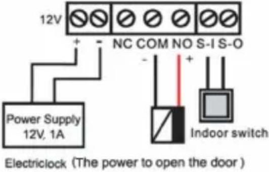 Graph 1 Graph 1 | 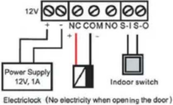 Graph 2 Graph 2 |
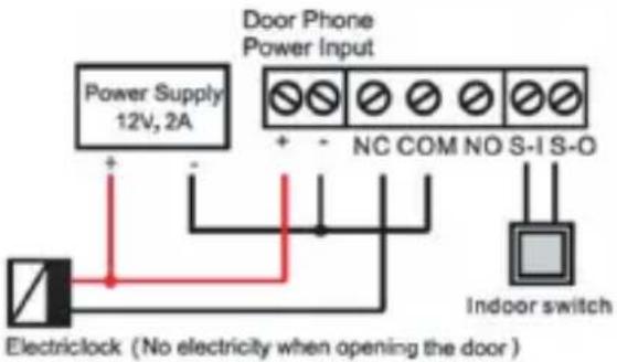 Graph 3 Graph 3 | 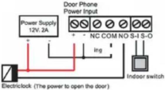 Graph 4 Graph 4 |
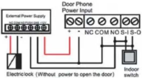 Graph 5 Graph 5 |
3. Installation
The HDP-5240PT is constructed of four parts as shown below. Prior to the installation, the installer is required to remove the front panel of the HDP-5240PT for wall mounting. Please follow the steps below for the installation.

Figure 1 Three Major Parts of HDP-5240PT
Step 1: Installation preparation
A. Check the following contents:
■ Hex wrench x 1
■ RJ45 plugs x 2 (1 spare)
■ KA4 x 25mm screws x 4
■ 25mm screw anchors x 4
B. Tools that may be required:
■ Hex wrench
■ Phillips screwdriver (Ph2 or Ph3), hammer, RJ45 crimper
■ Electric impact drill with an 6mm drill bit.
Step 2: Drilling

Figure 2 Wall Mounting
A. Place the mounting template with dimensions on the surface of a wall in a desired flat position.
B. Use an electric drill to drill the 4 holes marked on the mounting template. It is recommended to drill about 30mm deep. Remove the template when finishing drilling.
C. Push or hammer screw anchors into the drilled holes.
Step 3: Removing Hanging Panel
A. Remove the hanging shell in Figure 3 and Figure 4.

natural_image
Pure diagram of a rectangular object with an arrow indicating direction, no text or symbols present.
natural_image
Technical line drawing of a mechanical component with two views showing internal structure (no text or symbols)Figure 3
Figure 4
B. With Phillips screwdriver, unpack the Back Panel and the main part of intercom as shown in Figure 5.

Figure 5
Step 4: Hanging Shell Fixing and Cabling

Figure 6
A. Select the hole for cable supply; cable length of 15cm to 20cm is recommended.
B. With 4 KA4 x 25mm screws, tighten the wall-mounted hanging shell as shown in Figure 6.
Step 5: Connection Line

natural_image
Technical line drawing of a mechanical assembly with cross-sectional view (no text or symbols)Figure 7

Figure 8
A. Select the hole for cable supply.
B. Connect the cables of RJ45, power, and electric-lock to the motherboard socket as mentioned in connectors description (refer to Section 2).
C. Test whether there is electricity by doing the following:
- Press the # button for 3 seconds to get the IP address of intercom by voice.
- Input access password or press the indoor switch to check electric-lock installation.

Note
Do not proceed mounting until you have finished checking the electricity!
Step 6: Mounting

natural_image
Technical diagram showing a device with internal components and directional arrows, no readable text or symbols present.Figure 9

natural_image
Technical diagram showing a device mounted on a wall with a vertical pipe and directional arrows indicating movement (no text or symbols present)Figure 10
A. Use the 4 screws to tighten the main part of intercom on the back panel as shown in Figure 9.
B. Push the device into the wall-mounted hanging shell and tighten it with 1 screw as shown in Figure 10.
C. Make sure the screws have been tightened properly for better water-proof effect.
4. Searching Door Phone IP Address
There are two methods as shown below to search the HDP-5240P.
Method 1:
Open the Planet Door Phone Finder Utility. Press the Refresh button to search the HDP-5240PT and find the IP address.
| # | IP Address | Serial Number | MAC Address | SW Version | Description |
| 1 | 192.168.1.158 | HDP-5240PT | A8 F7 E0 00:00:00 | 12.1072.633.14. | IP Doorphone |
Method 2:
Press and hold the “#” key for 3 seconds and the door phone will report the IP address by voice.

| Default Setting | |
| Default DHCP Client Off | |
| Default IP Address 172.16.0.1 | |
| Default Web Port 80 | |
| Default Login User Name admin | |
| Default Login Password 123 | |
| Report IP address | Hold # key for 3 seconds to report IP address by voice |
| Searching Tools Planet Door | Phone Finder |
5. SIP Door Phone Setting
Please refer to the following steps to set the SIP door phone.
Step 1: Login the homepage of the HDP-5240PT.

Step 2: Add the SIP account.
Set SIP server address, port, user name, password and SIP user with assigned SIP account parameters.
Select "Activate", and then click Apply to save this setting.

Step 3: Setting Function (DSS) key
Set the DSS key as shown below for a quick start. Click "Apply" to save this setting.
Type: Hot Key
Number 1: The DSS Key will dial to this Number 1.
Number 2: If Number 1 is unavailable, it will be forwarded to Number 2.
Line: Working line
Subtype: Speed dial

Step 4: Door Phone Setting

6. Door Unlocking Setting
Local
Local Password
Step 1: Go to Features → Advanced Settings → Set Local Password (The default is "6789").
Step 2: Use the device's Numeric Keyboard to input password and “#” key, and then the door will be unlocked.

Private Access Code
Step 1: Go to RFID Cards → Access Code Action select Remote call and Local Auth.
Step 2: Use the device's Numeric Keyboard to input password and “#” key, and then the door will be unlocked.

Remote
Remote Password
Step 1: Go to Features → Advanced Settings → Set Remote Password (The default is "*").
Step 2: To answer the call made by visitor via SIP phone, press the “*” key to unlock the door the visitor.

RFID Card
Step 1: Go to RFID Cards → RFID Access → Enter the ID of RFID card (Only Front 10 yards) → Press Add to Door Card Table.
Step 2: Use pre assigned RFID cards to unlock the door by touching RFID area of device.

7. Customer Support
Thank you for purchasing PLANET products. You can browse our online FAQ resource and User's Manual on PLANET Web site first to check if solve your issue. If you need more support information, please contact PLANET Home Automation support team.
PLANET online FAQs:
Door Phone support team mail address:
HDP-5240PT User's Manual:
http://www.planet.com.tw/en/support/download.php?view=3&key=HDP-5240PT#list

Copyright © PLANET Technology Corp. 2017.
Contents are subject to revision without prior notice.
PLANET is a registered trademark of PLANET Technology Corp. All other trademarks belong to their respective owners.
- 720p SIP Multi-unit Video Door Phone with RFID and PoE
- Table of Contents
- Package Contents
- Physical Specifications
- Front Panel
- I/O Control Description
- Power Connector
- Network Connector
- Power and Electric-lock Connector
- JP1 Jumper
- Wiring instructions
- Installation
- Step 1: Installation preparation
- Step 2: Drilling
- Step 3: Removing Hanging Panel
- Step 5: Connection Line
- Searching Door Phone IP Address
- Method 1:
- Method 2:
- SIP Door Phone Setting
- Door Unlocking Setting
- Local
- Local Password
- Private Access Code
- Remote
- RFID Card
- Customer Support
Brand : Planet
Model : HDP-5240PT
Category : Intercom