
TBUS-1AXL-BC - Electrical Connectors Kramer - Free user manual and instructions
Find the device manual for free TBUS-1AXL-BC Kramer in PDF.


| Product Type | Table Connectivity Box |
| Model | TBUS-1AXL-BC |
| Brand | Kramer |
| Dimensions (HxWxD) | 1.7 x 4.5 x 3.1 in (43 x 114 x 79 mm) |
| Weight | 0.5 lb (0.23 kg) |
| Power Supply | Passive (no external power required) |
| Connectivity | 1x 3.5mm stereo audio input, 1x 3.5mm stereo audio output, 1x RCA composite video input |
| Material | Aluminum faceplate with black anodized finish |
| Color | Black (BC) |
| Mounting | Flush mount in table or wall (single gang) |
| Compatibility | Kramer TBUS system, standard AV equipment |
| LED Indicators | None |
| Operating Temperature | 32–104°F (0–40°C) |
| Maintenance | Clean with a dry, soft cloth; do not use liquid cleaners |
| Safety | Keep away from moisture; do not expose to extreme temperatures |
| Spare Parts & Repairability | Spare parts not available; non-repairable; replace unit if faulty |
| General Information | Designed for discreet AV signal routing in conference rooms and presentation spaces |
Frequently Asked Questions - TBUS-1AXL-BC Kramer
User questions about TBUS-1AXL-BC Kramer
0 question about this device. Answer the ones you know or ask your own.
Ask a new question about this device
Download the instructions for your Electrical Connectors in PDF format for free! Find your manual TBUS-1AXL-BC - Kramer and take your electronic device back in hand. On this page are published all the documents necessary for the use of your device. TBUS-1AXL-BC by Kramer.
USER MANUAL TBUS-1AXL-BC Kramer
Table Connection Bus
TBUS-1Axl Quick Start Guide
This page guides you through a basic installation and first-time use of your TBUS-1Axl. For more detailed information, see the TBUS-1Axl user manual and modular instruction sheets. You can download the latest manual at http://www.kramerelectronics.com.
Step 1: Check what's in the box

TBUS-1Axl Table Connection Bus Enclosure
2 table clamps
6 self locking ties

1 Cut out Template
1 Quick start guide
1 User Manual

natural_image
Illustration of a cardboard box with lid and front panel (no text or symbols)Save the original box and packaging materials in case your Kramer product needs to be returned to the factory for service.
Step 2: Prepare the TBUS-1Axl for mounting
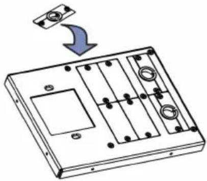
Assemble the Inner Frame.
natural_image
Technical line drawing of a mechanical component with mounting holes and internal compartments (no text or symbols)Install the power socket(s).

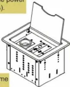
Adjust the height of the Inner Frame.
Mount the Inner Frame into the TBUS-1Axl enclosure.
Step 3: Prepare the table for mounting
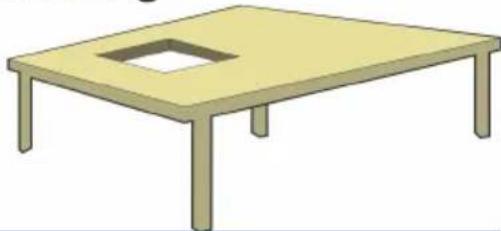
Cut out an opening in the table using the cut out template.
natural_image
Simple illustration of a four-legged table with a square cutout on top (no text or symbols)Step 4: Install the TBUS-1Axl to the table
Insert the Unit through the table opening.
Secure the unit to the table.
Connect the cables.

natural_image
Isometric diagram of a mechanical device with arrows indicating force or movement (no text or symbols)


natural_image
Technical line drawing of a mechanical assembly with no visible text or symbolsContents
1 Introduction 1
2 Getting Started 2
2.1 Achieving the Best Performance 2
2.2 Glossary 2
3 Overview 3
4 Your TBUS-1Axl Enclosure 4
4.1 TBUS-1Axl Optional Inner Frames 5
4.2 TBUS-1Axl Accessories 6
4.3 Power Socket Options 7
4.4 Power Cord Options 9
5 Installing the TBUS-1Axl 10
5.1 Assembling the Inner Frame 10
5.2 Installing the Inner Frame 14
5.3 Cutting an Opening in the Table 15
5.4 Inserting the TBUS-1Axl through the Cut Out Opening 16
5.5 Connecting the Cables 16
5.6 Inserting the Pass-through Cables 17
5.7 Adjusting the Height of the Inner Frame 18
6 Using the TBUS-1Axl 19
7 Technical Specifications of the Assembled TBUS-1Axl 20
Figures
Figure 1: TBUS-1Axl inside a Table 3
Figure 2: TBUS-1Axl Enclosure Top View 4
Figure 3: TBUS-1Axl Inner Frame (P/N: 80-000299) 11
Figure 4: Installing a Kramer TOOL 12
Figure 5: Installing the T-TBLANK TOOL Blank 12
Figure 6: T-RC8IR (P/N: 80-000599) 13
Figure 7: RC-8IR Faceplate holesTable Connection Bus 13
Figure 8: Cut out Dimensions 15
Figure 9: Inserting TBUS-1Axl into the Prepared Opening 16
Figure 10: Cable Pass-through Insert (P/N: 80-000399) 17
Figure 11: TBUS-1Axl Boardroom Installation 19
1 Introduction
Welcome to Kramer Electronics! Since 1981, Kramer Electronics has been providing a world of unique, creative, and affordable solutions to the vast range of problems that confront the video, audio, presentation, and broadcasting professional on a daily basis. In recent years, we have redesigned and upgraded most of our line, making the best even better!
Our 1,000-plus different models now appear in 11 groups that are clearly defined by function: GROUP 1: Distribution Amplifiers, GROUP 2: Switchers and Matrix Switchers, GROUP 3: Control Systems, GROUP 4: Format/Standards Converters, GROUP 5: Range Extenders and Repeaters, GROUP 6: Specialty AV Products, GROUP 7: Scan Converters and Scalers, GROUP 8: Cables and Connectors, GROUP 9: Room Connectivity, GROUP 10: Accessories and Rack Adapters and GROUP 11: Sierra Products.
Thank you for purchasing the Kramer TBUS-1Axl enclosure, which is ideal for boardrooms, conference and training rooms!

Note that the inner frame, power socket assembly, power cord and other inserts for the TBUS-1Axl enclosure are purchased separately.
2 Getting Started
We recommend that you:
- Unpack the equipment carefully and save the original box and packaging materials for possible future shipment
• Review the contents of this user manual
• Use Kramer high-performance high-resolution cables

Go to http://www.kramerelectronics.com to check for up-to-date user manuals, a complete list of Kramer wall plates and module connectors, application programs, and to check if firmware upgrades are available (where appropriate).
2.1 Achieving the Best Performance
To achieve the best performance:
- Use only good quality connection cables to avoid interference, deterioration in signal quality due to poor matching, and elevated noise levels (often associated with low quality cables)
- Avoid interference from neighboring electrical appliances that may adversely influence signal quality
- Position your Kramer TBUS-1Axl away from moisture, excessive sunlight and dust
2.2 Glossary
| Inner frame | The inner frame fits into the TBUS enclosure |
| Universal socket | The Universal socket fits almost all power cords, worldwide |
| Insert | The insert is fitted in the inner frame. Go to our Web site to check for a variety of single and dual sized inserts |
3 Overview
The TBUS-1Axl is a modular furniture-mounted connection bus enclosure that is easily installed into a table or podium top. Once assembled, the TBUS-1Axl lets you connect any equipment to the room's presentation system installations via cable access or passive interfaces (see Figure 1). When the cables are not in use, they can be stored inside the unit, covered by the lid and out of sight.
In addition, the TBUS-1Axl features:
- A modular design, letting you tailor the TBUS-1Axl according to your requirements
- A black anodized or brushed clear aluminum lid with a special opening for cable pass-through, (note, that other customized colors can also be ordered)
- Height adjustment screw holes to set the inner frame (ordered separately) to the desired height
- Single or dual power socket openings that are suitable for any of the following power sockets: for the USA, Germany (the Europlug), Belgium-France, Italy, Australia, Israel, South Africa or “Universal” for use anywhere (see compatibility restrictions in Section 7)
Order the power sockets separately from Kramer Electronics

natural_image
Illustration of a wooden table with a laptop and mouse on top (no text or symbols)Figure 1: TBUS-1Axl inside a Table

Do not place heavy objects on top of the TBUS-1Axl.
4 Your TBUS-1Axl Enclosure

Figure 2: TBUS-1Axl Enclosure Top View
| # | Feature | Function | |
| 1 Black Anodized/Brushed Clear Textured Lid | Includes an opening for cable pass-through; covers the inner frame, leaving the table surface neat and tidy | ||
| 2 Outer Rim Fits over the table | surface.A protective rubber guard protects the outer rim during shipping.Remove it before installing the unit | ||
| 3 | Enclosure | Inserted into the table cut out | |
| 4 TOOL Height Adjustment Screw Holes | Used for installing Kramer TOOLS | ||
| 5 | Tie Holes | Insert the self-locking tie through the holes to fix the pass-through cables to the inside walls of the unit | |
| 6 | Bracket Slits | For attaching the two mounting brackets on opposite sides | |
| 7 | Table Clamping Set | Rubber Protectors Protect the table surface when mounting the unit and ensure soft tightening to the table underside (one for each clamp) | |
| 8 | Butterfly Screws | Tighten to lock the mounting butterfly screw (one for each clamp) | |
| 9 | Butterfly Screws | Tighten to secure the unit to the table surface (one for each clamp) | |
| 10 | Mounting Brackets (2 units) | Place in the bracket slits after inserting the enclosure into the table – for securing the unit to the table surface (one for each clamp) | |
| 11 | Inner Frame Height Adjustment Screw Holes | For adjusting the height of the mounted inner frame | |
4.1 TBUS-1Axl Optional Inner Frames
The following inner frames can be installed in the TBUS-1Axl enclosure:
| Inner Frames for TBUS-1A | Specifications (define what you can include in this inner frame): |
 | T1AF-16 (P/N: 80-000299)1 opening for 1 power socket2 cable pass-through inserts4 blank inserts |
 | T1AF-26 (P/N: 80-000399)1 opening for 2 power sockets2 cable pass-through inserts4 blank inserts |
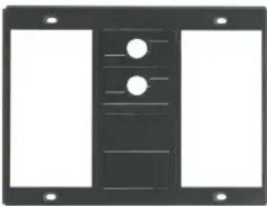 | T1AF-44 (P/N: 80-000499)2 openings for 4 power sockets2 cable pass-through inserts2 blank inserts |
 | T1AF-14L (P/N: 80-000699)1 opening for 1 power socket1 opening for Kramer SI-1VGA / RC-3TB2 cable pass-through inserts2 blank inserts |
 | T1AF-1T3 (P/N: 80-005199)1 opening for 1 power socket2 openings for 3 Kramer TOOLs |
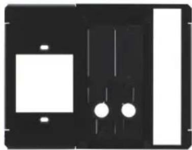 | T1AF-14T (P/N: 80-005299)1 opening for 1 power socket1 opening for 1 Kramer TOOL2 cable pass-through inserts2 blank inserts |

Custom made inner frames can be designed if required.
Contact Kramer Electronics for more details.
4.2 TBUS-1Axl Accessories
| Accessories Description | |
| Inserts | You can install any wall plate devices as well as any of the single or dual inserts—see our Web site for details. |
 | T-RC8IR (P/N: 80-000599)1 special panel to fit the Kramer RC-8IR Control Panel into the appropriate frame(P/N 80-000399 or P/N 80-000499 instead of two power sockets) |
 | T-2INSERT (P/N: 80-00006699)The T-2INSERT kit can be installed inside a single power socket opening and includes:1 single cable pass-through insert1 dual cable pass-through insert |
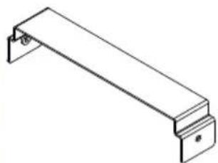 | T-TBLANK (P/N: 80-005099)This TOOL blank covers a TOOL opening for the T1AF-1T3 (P/N: 80-005199) and T1AF-14T (P/N: 80-005299) inner frames |
4.3 Power Socket Options
A choice of one or more power sockets per inner frame is available in several versions, including power sockets for the USA, Germany (the Europlug), Belgium-France, Italy, South Africa, Israel and Australia. A “Universal” socket for general use is also available (see the compatibility restrictions in the table below).
The Single Power Socket Assemblies
| Power Socket Type | Power Specs | ||
Universal: | TS/1U (80-000899)100-240V AC, 50/60Hz, 5AMaximum 5A per power outlet | Fully compatible with power plugs in the UK, India, Italy and Denmark, as well as with the 2-prong Europlug.Partially compatible (if the polarity is reversed) with plugs in China, Switzerland, Israel and the USA. The universal socket does not supply grounding to plugs in Central Europe and France and so you should order country specific sockets instead.Not compatible with South African plugs. | |
| Power Socket Type | Power Specs Power Socket | Type | Power Specs |
USA: | TS-1US (80-000999)100-240V AC, 50/60Hz, 5AMaximum 5A per power outlet | Italy: | TS-1IT (80-001499)100-240V AC, 50/60Hz, 5AMaximum 5A per power outlet |
Germany and EU: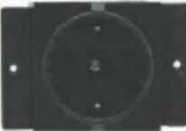 | TS-1DE (80-001299)100-240V AC, 50/60Hz, 5AMaximum 5A per power outlet | Australia: | TS-1AU (80-001599)100-240V AC, 50/60Hz, 5AMaximum 5A per power outlet |
Belgium and France: | TS-1FR (80-001399)100-240V AC, 50/60Hz, 5AMaximum 5A per power outlet | Israel: | TS-1IL (80-001799)220V AC, 50/60Hz, 5AMaximum 5A per power outlet |
South Africa | TS-1ZA (80-001699)100-240V AC, 50/60Hz, 5AMaximum 5A per power outlet | ||
Dual power sockets are used for TBUS-1Axl with two or four power sockets:
| Dual Power Socket Assemblies: Power Specs | |
Universal: | TS-2U (80-001899)100-240V AC, 50/60Hz, 5AMaximum 5A/2.5A per power outlet |
USA: | TS-2US (80-001999)100-240V AC, 50/60Hz, 5AMaximum 5A/2.5A per power outlet |
Germany and EU: | TS-2DE (80-002199)100-240V AC, 50/60Hz, 5AMaximum 5A/2.5A per power outlet |
France: | TS-2FR (80-002299)100-240V AC, 50/60Hz, 5AMaximum 5A/2.5A per power outlet |
Italy | TS-2IT (80-002399)100-240V AC, 50/60Hz, 5AMaximum 5A/2.5A per power outlet |
Australia: | TS-2AU (80-002499)100-240V AC, 50/60Hz, 5AMaximum 5A/2.5A per power outlet |
Israel: | TS-2IL (80-002699)220V AC, 50/60Hz, 5AMaximum 5A/2.5A per power outlet |
South Africa: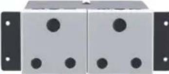 | TS-2ZA (80-002599)220V AC, 50/60Hz, 5AMaximum 5A/2.5A per power outlet |
4.4 Power Cord Options
You can order any of the following power cords to use with a modular TBUS:
| Power Cord Type | Description | P/N |
| 6ft/110V (North America) | C-AC/US (110V) | 91-000099 |
| 6ft/125V (Japan) | C-AC/JP (125V) | 91-000699 |
| 6ft/220V (Europe) | C-AC/EU (220V) | 91-000199 |
| 6ft/220V (Israel) | C-AC/IL (220V) | 91-000999 |
| 6ft/250V (UK) | C-AC/UK (250V) | 91-000299 |
| 6ft/250V (India) | C-AC/IN (250V) | 91-001099 |
| 6ft/250V/10A (China) | C-AC/CN (250V) | 91-001199 |
| 6ft/250V/10A (South Africa) | C-AC/ZA (250V) | 91-001299 |
To use one power cord for a 4-socket configuration, you can order any of the following types of power cords separately:
| Power Cord Type | Description | P/N |
| 110V Y-version (6ft), North America | C-ACY/US | 91-000399 |
| 220V Y-version (6ft), Europe | C-ACY/EU | 91-000499 |
| 240V Y-version (6ft), UK | C-ACY/UK | 91-000599 |
5 Installing the TBUS-1Axl
To install the TBUS-1Axl perform the following steps:
- Assemble the inner frame (see Section 5.1).
- Install the inner frame (see Section 5.2).
- Cut an opening in the table (see Section 5.3).
- Insert the unit through the opening and secure to the table (see Section 5.4).
- Connect the cables (see Section 5.5).
- Insert the pass-through cables (see Section 5.6).
- Adjust the height of the inner frame (see Section 5.7)
5.1 Assembling the Inner Frame
The modules mounted on the inner frame can include single inserts and/or dual inserts as well as power sockets and various Kramer devices. This section describes how to assemble these modules.

Each module kit comes with detailed assembly instructions.
5.1.1 Mounting the Inserts
You can rearrange or remove any of the plates mounted on the inner frame and replace them with Kramer passive wall plates or connector modules for interfacing A/V type signals.
To mount a Kramer insert or connector module:
- Unscrew the two screws that fasten the blank plate to the inner frame and remove the blank plate.
- Place the required Kramer insert over the opening, insert the two screws to fix the Kramer insert in place, and tighten them.

Figure 3: TBUS-1Axl Inner Frame (P/N: 80-000299)
| # Feature Function | ||
| 1 Split Grommets Push apart slightly to insert cables | ||
| 2 | Split Brackets | Support the split grommet for the pass through-cables |
| 3 | Blank Plates | Four blank covers that can be replaced with wall plates as required |
| 4 Power Socket Opening | Suitable for a single power socket or the T-2INSERT | |
| 5 Adjustable Height Screw Holes | For adjusting the height of the inner frame | |
5.1.2 Mounting the Power Socket Assemblies
To mount the power socket, place the power socket under the frame in its appropriate place and tighten with the two screws (supplied).

Power socket kits come with assembly instructions.
5.1.3 Mounting a Kramer TOOL
To mount a TOOL (for example, to the T1AF-14T), as shown in Figure 4:
- Screw the spacers to their designated places (one on each side).
-
Insert the TOOL, from beneath, through the TOOL opening.
-
Screw the screws (one on each side) through the frame holes and spacers.

Figure 4: Installing a Kramer TOOL
5.1.4 Installing the TOOL Blank
To install the T-TBLANK, as shown in Figure 5:
- Insert the T-TBLANK from beneath, through the TOOL opening.
- Screw the screws (one on each side) through the frame.

Figure 5: Installing the T-TBLANK TOOL Blank
5.1.5 Mounting the Special Panel for RC-8IR
The Kramer T-RC8IR for the TBUS-1Axl Table Connection bus is used to fit the Kramer RC-8IR Control Panel into the appropriate frame (P/N 80-000399 or P/N 80-000499 instead of two power sockets).

Figure 6: T-RC8IR (P/N: 80-000599)
Remove the RC-8IR Faceplate
- Before installing the T-RC8IR, unscrew the two faceplate attachment screws and remove the RC-8IR faceplate.

Figure 7: RC-8IR Faceplate holesTable Connection Bus
- Place the T-RC8IR over the RC-8IR enclosure so that both face plate holes are aligned with the face plate holes on the RC-8IR enclosure and the IR IN receiver fits into the IR IN opening.
- Insert the faceplate screws through the T-RC8IR and RC-8IR enclosure faceplate holes, and tighten.
Installation Instructions
To install the T-RC8IR:
- Insert the T-RC8IR assembly through the dual power socket opening from beneath.
- Use the two power socket screws to tighten the T-RC8IR assembly in place.
5.1.6 Installing the SI-1VGA / RC-3TB
To install the SI-1VGA / RC-3TB module, place it under the designated opening in the T1AF-14L (P/N: 80-000699) and then screw and tighten it in place using two screws supplied with the inner frame.
5.2 Installing the Inner Frame
To install the inner frame:
- Place the inner frame inside the TBUS-1Axl enclosure.
- Set the required height using your fingers to bring the inner frame to the desired position, screw and tighten it in place using the height adjustment screws (supplied with the inner frame).

Inner frame kits come with assembly instructions.
5.3 Cutting an Opening in the Table
To cut an opening in the table:
- Place the included cut out template (that is included with your TBUS-1Axl) on the surface of the table exactly where you want to install the TBUS-1Axl.
- Attach the template to the table with the included screws (if using the cut out template).
- Following the inside edge of the template, cut a hole in the table surface with a sabre or keyhole saw according to the dimensions shown in Figure 8 (not to scale).

The thickness of the table should be 76.2 mm / 3 inches or less.

Figure 8: Cut out Dimensions
- Unscrew and remove the template from the surface of the table and clean the table surface.
Take care not to damage the table.
If needed, you can download a full-scale template from our Web site.

Kramer Electronics is not responsible for any damage caused to the table.
5.4 Inserting the TBUS-1Axl through the Cut Out Opening
To install TBUS-1Axl in the opening:
-
Remove the protective rubber guard from around the outer rim of the TBUS-1Axl housing. Beware of the sharp edge!
-
Carefully insert the unit into the prepared opening (see Figure 9).
-
Take the support brackets under the table and place them into the support bracket grooves on both sides of the unit (see Figure 2, item 7).
-
Verify proper alignment of the unit before tightening the mounting screws.
-
Tighten both mounting butterfly screws upward until they reach the table surface (from underneath). Tighten firmly (see Figure 9).
-
Tighten the locking butterfly screws downward until tight against the mounting bracket.

natural_image
Isometric line drawing of a rectangular electronic device with internal components and mounting base (no text or symbols)
natural_image
Technical line drawing of a mechanical device with mounting brackets and wiring (no text or symbols)Figure 9: Inserting TBUS-1Axl into the Prepared Opening
5.5 Connecting the Cables
When replacing blank inserts with connector inserts (for example, VGA, audio, HDMI and so on):
-
Insert the cables to their appropriate connectors from underneath.
-
Secure the cables to the tie holes on the TBUS-1Axl.
Do not secure the cables too tightly or too loosely. Leave a small amount of slack.
5.6 Inserting the Pass-through Cables
To insert the pass through cables (for example, to connect a laptop) do the following:
-
Remove the two screws attaching the split pass-through bracket.
-
Remove the split grommet.
-
Insert the cable through the rectangular opening.
-
Open the split grommet slightly and insert the required cables.
-
Place the split bracket around the grommet and position this assembly over the inner frame.
-
Place the two screws appropriately and tighten the split bracket together with the grommet and inserted cables to the inner frame.
-
Insert the self-locking ties through the tie holes to secure the cables to the inside walls of the enclosure.

natural_image
Technical line drawing of a rectangular electronic enclosure with multiple compartments and mounting holes (no text or symbols)Figure 10: Cable Pass-through Insert (P/N: 80-000399)
5.7 Adjusting the Height of the Inner Frame
If needed, you can adjust the inner frame height to accommodate large or bulky cables. To adjust, perform the following:
- Remove the height adjustment screws, while supporting the surface from underneath with your fingers.
- Raise or lower the inner frame to the required height, insert the screws, and tighten them in place.
6 Using the TBUS-1Axl
Once the TBUS-1Axl is installed, you can easily customize it to suit your own requirements by plugging in the required A/V equipment, as illustrated in the example in Figure 11.

flowchart
graph TD
    A["Display"] -->|VGA| B["Video Conference"]
    B -->|Communication| A
    C["Computer Graphics Source"] -->|Ethernet| B
    D["Laptop"] -->|Ethernet| B
    E["Projector"] -->|VGA| B
    F["Power Amplifier with Speakers"] -->|Audio| B
    G["TBUS-1Axl"] -->|RS-232| H["Kramer Switcher/Scaler"]
    B -->|AC Power| C
Figure 11: TBUS-1Axl Boardroom Installation
7 Technical Specifications of the Assembled TBUS-1Axl
| POWER SOURCE(AC power limits): | Single Socket Assemblies: | |
| Universal | 100-240V AC, 50/60Hz, 5AMaximum 5A per power outlet | |
| Fully compatible with power plugs in the UK, India, Italy and Denmark, as well as with the 2-prong Europlug. Partially compatible (if the polarity is reversed) with plugs in China, Switzerland, Israel and the USA. The universal socket does not supply grounding to plugs in Central Europe and France (you should order country specific sockets instead). Not compatible with South African plugs. | ||
| USA | 100-240V AC, 50/60Hz, 5AMaximum 5A per power outlet | |
| Germany and EU | 100-240V AC, 50/60Hz, 5AMaximum 5A per power outlet | |
| Belgium and France | 100-240V AC, 50/60Hz, 5AMaximum 5A per power outlet | |
| Italy | 100-240V AC, 50/60Hz, 5AMaximum 5A per power outlet | |
| Australia | 100-240V AC, 50/60Hz, 5AMaximum 5A per power outlet | |
| Israel | 220V AC, 50/60Hz, 5AMaximum 5A per power outlet | |
| South Africa | 220V AC, 50/60Hz, 5AMaximum 5A per power outlet | |
| Dual Power Kit Assemblies: | ||
| Universal | 100-240V AC, 50/60Hz, 5AMaximum 5A/2.5A per power outlet | |
| USA 100-240V AC, 50/60Hz, 5AMaximum 5A/2.5A per power outlet | ||
| Germany and EU | 100-240V AC, 50/60Hz, 5AMaximum 5A/2.5A per power outlet | |
| France 100-240V AC, 50/60Hz, 5AMaximum 5A/2.5A per power outlet | ||
| Israel 220V AC, 50/60Hz, 5AMaximum 5A/2.5A per power outlet | ||
| South Africa 220V AC, 50/60Hz, 5AMaximum 5A/2.5A per power outlet | ||
| FUSE RATING: T 6.3A 250V | ||
| OPERATING TEMPERATURE RANGE: +5 to | +45 Deg. Centigrade | |
| OPERATING HUMIDITY RANGE: | 10 to 90% RHL, non-condensing | |
| STORAGE TEMPERATURE RANGE: -20 to +70Deg. C. | ||
| STORAGE HUMIDITY RANGE: | 5 to 95% RHL, non-condensing | |
| DIMENSIONS: | 22.1cm x 18.2cm x 13cm (8.17" x 5.88" x 5.13") W, D, H | |
| WEIGHT: | TBUS-1A: 1.5kg (3.3lbs) approx.; Table clamps: 0.26kg (0.57lbs); Metal template: 0.125kg (0.28lbs) | |
| ACCESSORIES: | Power cord, six self-locking ties, metal template | |
| OPTIONS: | Inner frames, passive wall plates and interfaces, power socket kits, power cord | |
| Specifications are subject to change without notice at http://www.kramerelectronics.com | ||
LIMITED WARRANTY
The warranty obligations of Kramer Electronics for this product are limited to the terms set forth below:
What is Covered
This limited warranty covers defects in materials and workmanship in this product.
What is Not Covered
This limited warranty does not cover any damage, deterioration or malfunction resulting from any alteration, modification, improper or unreasonable use or maintenance, misuse, abuse, accident, neglect, exposure to excess moisture, fire, improper packing and shipping (such claims must be presented to the carrier), lightning, power surges, or other acts of nature. This limited warranty does not cover any damage, deterioration or malfunction resulting from the installation or removal of this product from any installation, any unauthorized tampering with this product, any repairs attempted by anyone unauthorized by Kramer Electronics to make such repairs, or any other cause which does not relate directly to a defect in materials and/or workmanship of this product. This limited warranty does not cover cartons, equipment enclosures, cables or accessories used in conjunction with this product.
Without limiting any other exclusion herein, Kramer Electronics does not warrant that the product covered hereby, including, without limitation, the technology and/or integrated circuit(s) included in the product, will not become obsolete or that such items are or will remain compatible with any other product or technology with which the product may be used.
How Long Does this Coverage Last
Seven years as of this printing; please check our Web site for the most current and accurate warranty information.
Who is Covered
Only the original purchaser of this product is covered under this limited warranty. This limited warranty is not transferable to subsequent purchasers or owners of this product.
What Kramer Electronics will do
Kramer Electronics will, at its sole option, provide one of the following three remedies to whatever extent it shall deem necessary to satisfy a proper claim under this limited warranty:
-
Elect to repair or facilitate the repair of any defective parts within a reasonable period of time, free of any charge for the necessary parts and labor to complete the repair and restore this product to its proper operating condition. Kramer Electronics will also pay the shipping costs necessary to return this product once the repair is complete.
-
Replace this product with a direct replacement or with a similar product deemed by Kramer Electronics to perform substantially the same function as the original product.
-
Issue a refund of the original purchase price less depreciation to be determined based on the age of the product at the time remedy is sought under this limited warranty.
What Kramer Electronics will not do Under This Limited Warranty
If this product is returned to Kramer Electronics or the authorized dealer from which it was purchased or any other party authorized to repair Kramer Electronics products, this product must be insured during shipment, with the insurance and shipping charges prepaid by you. If this product is returned uninsured, you assume all risks of loss or damage during shipment. Kramer Electronics will not be responsible for any costs related to the removal or re-installation of this product from or into any installation. Kramer Electronics will not be responsible for any costs related to any setting up this product, any adjustment of user controls or any programming required for a specific installation of this product.
How to Obtain a Remedy under this Limited Warranty
To obtain a remedy under this limited warranty, you must contact either the authorized Kramer Electronics reseller from whom you purchased this product or the Kramer Electronics office nearest you. For a list of authorized Kramer Electronics resellers and/or Kramer Electronics authorized service providers, please visit our web site at www.kramerelectronics.com or contact the Kramer Electronics office nearest you.
In order to pursue any remedy under this limited warranty, you must possess an original, dated receipt as proof of purchase from an authorized Kramer Electronics reseller. If this product is returned under this limited warranty, a return authorization number, obtained from Kramer Electronics, will be required. You may also be directed to an authorized reseller or a person authorized by Kramer Electronics to repair the product.
If it is decided that this product should be returned directly to Kramer Electronics, this product should be properly packed, preferably in the original carton, for shipping. Cartons not bearing a return authorization number will be refused.
Limitation on Liability
THE MAXIMUM LIABILITY OF KRAMER ELECTRONICS UNDER THIS LIMITED WARRANTY SHALL NOT EXCEED THE ACTUAL PURCHASE PRICE PAID FOR THE PRODUCT. TO THE MAXIMUM EXTENT PERMITTED BY LAW, KRAMER ELECTRONICS IS NOT RESPONSIBLE FOR DIRECT, SPECIAL, INCIDENTAL OR CONSEQUENTIAL DAMAGES RESULTING FROM ANY BREACH OF WARRANTY OR CONDITION, OR UNDER ANY OTHER LEGAL THEORY. Some countries, districts or states do not allow the exclusion or limitation of relief, special, incidental, consequential or indirect damages, or the limitation of liability to specified amounts, so the above limitations or exclusions may not apply to you.
Exclusive Remedy
TO THE MAXIMUM EXTENT PERMITTED BY LAW, THIS LIMITED WARRANTY AND THE REMEDIES SET FORTH ABOVE ARE EXCLUSIVE AND IN LIEU OF ALL OTHER WARRANTIES, REMEDIES AND CONDITIONS, WHETHER ORAL OR WRITTEN, EXPRESS OR IMPLIED. TO THE MAXIMUM EXTENT PERMITTED BY LAW, KRAMER ELECTRONICS SPECIFICALLY DISCLAIMS ANY AND ALL IMPLIED WARRANTIES, INCLUDING, WITHOUT LIMITATION, WARRANTIES OF MERCHANTABILITY AND FITNESS FOR A PARTICULAR PURPOSE. IF KRAMER ELECTRONICS CANNOT LAWFULLY DISCLAIM OR EXCLUDE IMPLIED WARRANTIES UNDER APPLICABLE LAW, THEN ALL IMPLIED WARRANTIES COVERING THIS PRODUCT, INCLUDING WARRANTIES OF MERCHANTABILITY AND FITNESS FOR A PARTICULAR PURPOSE, SHALL APPLY TO THIS PRODUCT AS PROVIDED UNDER APPLICABLE LAW.
IF ANY PRODUCT TO WHICH THIS LIMITED WARRANTY APPLIES IS A "CONSUMER PRODUCT" UNDER THE MAGNUSON-MOSS WARRANTY ACT (15 U.S.C.A. §2301, ET SEQ.) OR OTHER APPLICABLE LAW, THE FOREGOING DISCLAIMER OF IMPLIED WARRANTIES SHALL NOT APPLY TO YOU, AND ALL IMPLIED WARRANTIES ON THIS PRODUCT, INCLUDING WARRANTIES OF MERCHANTABILITY AND FITNESS FOR THE PARTICULAR PURPOSE, SHALL APPLY AS PROVIDED UNDER APPLICABLE LAW.
Other Conditions
This limited warranty gives you specific legal rights, and you may have other rights which vary from country to country or state to state.
This limited warranty is void if (i) the label bearing the serial number of this product has been removed or defaced, (ii) the product is not distributed by Kramer Electronics or (iii) this product is not purchased from an authorized Kramer Electronics reseller. If you are unsure whether a reseller is an authorized Kramer Electronics reseller, please visit our Web site at www.kramerelectronics.com or contact a Kramer Electronics office from the list at the end of this document.
Your rights under this limited warranty are not diminished if you do not complete and return the product registration form or complete and submit the online product registration form. Kramer Electronics thanks you for purchasing a Kramer Electronics product. We hope it will give you years of satisfaction.

For the latest information on our products and a list of Kramer distributors, visit our Web site where updates to this user manual may be found.
We welcome your questions, comments, and feedback.
Web site: www.kramerelectronics.com
E-mail: info@kramerel.com


SAFETY WARNING
Disconnect the unit from the power supply before opening and servicing
- TBUS-1Axl Quick Start Guide
- Step 1: Check what's in the box
- Step 2: Prepare the TBUS-1Axl for mounting
- Step 3: Prepare the table for mounting
- Step 4: Install the TBUS-1Axl to the table
- Contents
- Introduction 1
- Getting Started 2
- Overview 3
- Your TBUS-1Axl Enclosure 4
- Installing the TBUS-1Axl 10
- Using the TBUS-1Axl 19
- Technical Specifications of the Assembled TBUS-1Axl 20
- Figures
- Introduction
- Getting Started
- Achieving the Best Performance
- Glossary
- Overview
- Your TBUS-1Axl Enclosure
- TBUS-1Axl Optional Inner Frames
- TBUS-1Axl Accessories
- Power Socket Options
- Power Cord Options
- Installing the TBUS-1Axl
- Assembling the Inner Frame
- Mounting the Inserts
- Mounting the Power Socket Assemblies
- Mounting a Kramer TOOL
- Installing the TOOL Blank
- Mounting the Special Panel for RC-8IR
- Remove the RC-8IR Faceplate
- Installation Instructions
- To install the T-RC8IR:
- Installing the SI-1VGA / RC-3TB
- Installing the Inner Frame
- To install the inner frame:
- Cutting an Opening in the Table
- Inserting the TBUS-1Axl through the Cut Out Opening
- Connecting the Cables
- Inserting the Pass-through Cables
- Adjusting the Height of the Inner Frame
- Using the TBUS-1Axl
- Technical Specifications of the Assembled TBUS-1Axl
- LIMITED WARRANTY
- What is Covered
- What is Not Covered
- How Long Does this Coverage Last
- Who is Covered
- What Kramer Electronics will do
- What Kramer Electronics will not do Under This Limited Warranty
- How to Obtain a Remedy under this Limited Warranty
- Limitation on Liability
- Exclusive Remedy
- Other Conditions
- SAFETY WARNING
Brand : Kramer
Model : TBUS-1AXL-BC
Category : Electrical Connectors