
5002 - Car alarm GEMINI - Free user manual and instructions
Find the device manual for free 5002 GEMINI in PDF.


| Product Type | Car Alarm with Central Locking and Ultrasonic |
| Brand | Gemini |
| Model | 5002 |
| Power Supply | 12 VDC |
| Current Draw | 12 mA |
| Working Temperature | -30° to +85°C |
| Engine Immobilisation Relay Contacts | 30 A |
| Visual Signalling Relay Contacts | 20 A |
| Audible Tone Relay Contacts | 2 A |
| Central Locking Relay Contacts | 10 A |
| Immunity | 50 V/m |
| Alarm Period | 25 - 30 seconds |
| Sound Level at 1 metre | 122 dB |
| Minimum Power Absorption to Trigger | 5 W |
| Transmitter Type | Cryptographic coded with Gemini Card |
| Panic Function | Yes |
| Passive Arming | Yes |
| Status LED | Indicates violated circuit |
| ACR Function | Automatic Current Reduction after 48 hours |
| RSD Function | Remote sensor isolation |
| Additional Siren Output | Yes |
| Hazard Lights Connection | Yes |
| Total Closure Facility | For selected vehicles |
| Ultrasonic Sensors | Included, adjustable sensitivity |
Frequently Asked Questions - 5002 GEMINI
User questions about 5002 GEMINI
0 question about this device. Answer the ones you know or ask your own.
Ask a new question about this device
Download the instructions for your Car alarm in PDF format for free! Find your manual 5002 - GEMINI and take your electronic device back in hand. On this page are published all the documents necessary for the use of your device. 5002 by GEMINI.
USER MANUAL 5002 GEMINI
5002/3 INSTALLATION INSTRUCTIONS
The Gemini 5002 and 5003 are remote controlled alarm units with built-in central door locking adapters, ultrasonic and total closure facility for selected vehicles. The 5002 and 5003 are complete with cryptographic coded transmitters complete with Gemini Card which has an alphanumeric code printed on it to enable you to get a replacement at any time. The units offer panic facility. The system also includes passive arming and provides outlets for supplementary sirens and the vehicle hazard lights circuit. There is also the optional audible signalling for arming and disarming. (The 5003 incorporates its own internal battery).
The alarms offer the following protections:
- The passenger compartment via pin switches and voltage drop sensing (can be isolated).
- Boot and bonnet by pin switches.
• Radio cassette and other accessories by "Accessory Loop" (can be isolated) - The engine immobilisation is obtained by the interruption of starter crank wire at the back of the ignition switch.
The alarms also have the following abilities:
• The control of additional sirens and negatively controlled horns.
- Can be connected to microwave, vibration and anti-lifting sensors.
- Can be connected to window closures and sunroof closures providing this operation DOES work off the drivers door key.
• The sensors can be isolated through the transmitter via R.S.D. function.
- A.C.R. Function (Automatic Current Reduction). For activation periods of 48 hours or more the unit will automatically switch off flashings LED and additional modules. This will save on current drain from the battery. If any attempted break-in occurs the alarm will trigger instantly.
- STATUS L.E.D. If the unit has been triggered, on disarming the system the LED will fash in a certain sequence to indicate which circuit has been violated.
PRE-INSTALLATION CHECKS
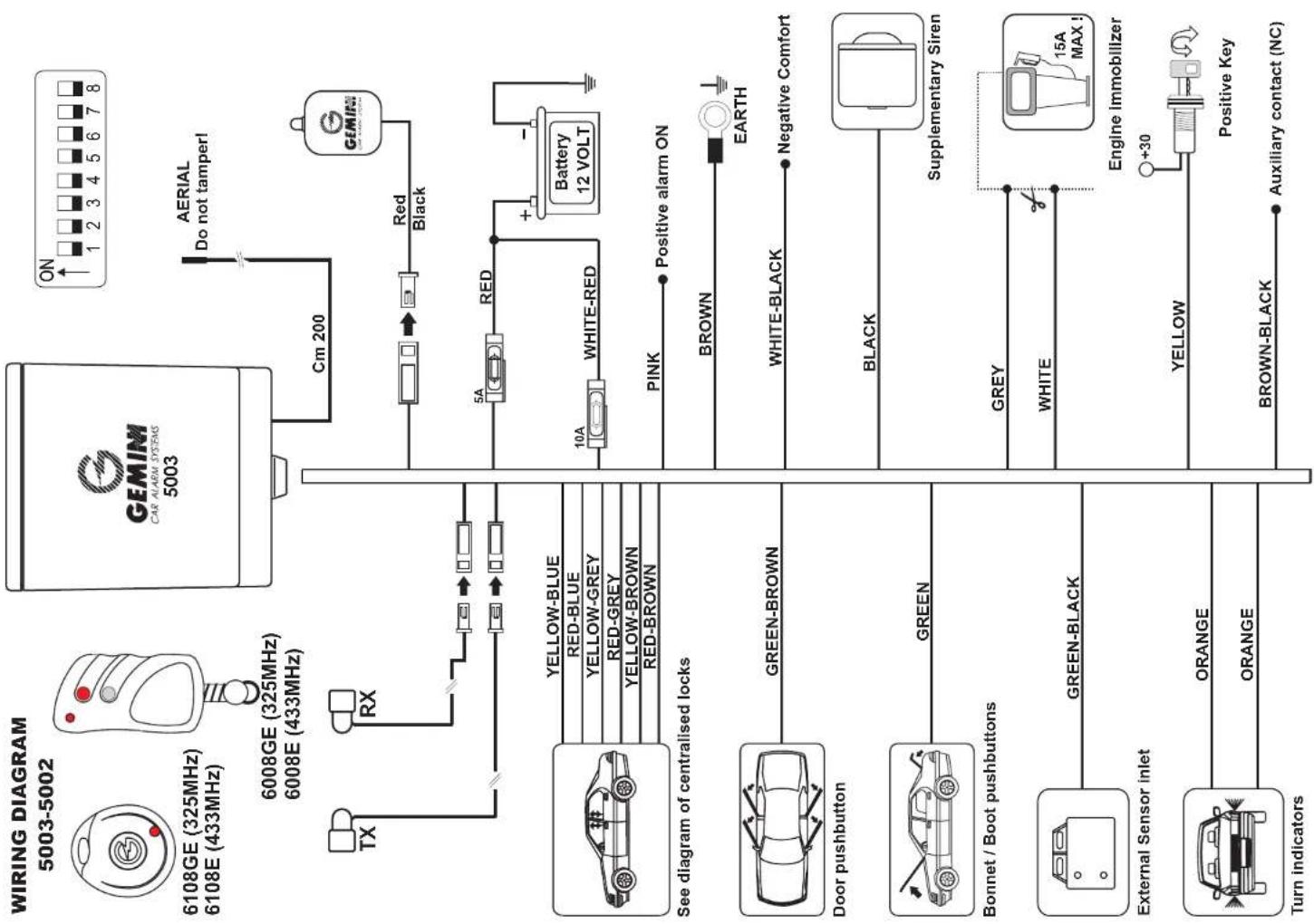
Disconnect terminals of the battery and only reconnect after the installation is complete, giving consideration to the vehicle characteristics. Set the alarm switches as required in Table C_1 . The compact unit must be mounted under the bonnet, away from areas of intense heat and direct water spray. It must be installed using supplied bracket. The harness installation is illustrated in the diagram.
WIRING INSTRUCTIONS REF. DIAGRAM No. 1.
| CABLE COLOURS | FUNCTION OF THE CONNECTION | CONNECTIONS TO CARRY OUT | |
| 1 | RED | Positive alarm feed | If the voltage sensing isactivatedthe RED wire must be connected to the interior light circuit in the main fuse box. If the voltage sensing isde-activatedthe RED wire can be connected to the main feed in the fuse box or directly to the battery positive terminal. The positive supply is protected by a 5 Amp fuse as supplied. |
| 2 | BROWN | Negative alarm feed | Connect theBROWNwire to a stable body earth using an existing body earth point or battery negative terminal. |
| 3 | RED-WHITE | Hazard Circuit Power Feed | The RED-WHITEwire must be connected to the main fuse feed or directly to the battery positive terminal, using the 10 Amp. fuse as supplied. |
| 4 | YELLOW | Ignition Live | Connect theYELLOWwire to an ignition positive feed. This wireMUSTremain "live" whilst starting the engine. (It is most important to connect this wire as it will prevent the alarm from being operated with the ignition "on" or the engine running). |
| 5 | ORANGE | Hazard Lights | Locate the left and right hand-side indicator wires. Connect oneORANGE wire on to each wire. |
| 6 | GREY and WHITE | Engine immobilisation | This function is obtained by locating the engine starter crank wire at the rear of the ignition key switch. (refer to: Vehicle Workshop Manual). Cut this wire and connect one side to theGREYwire and the other side to theWHITEwire. Remember to connect the alarmYELLOWwire (see point 4). |
| 7 | GREEN | Boot Bonnet/Tailgate Pin Switches | If there are no original pin switches in the vehicle, use the switches supplied in the kit. The connections for the pin switches are made onto theGREENwire, suitably mounted to avoid water channel and areas of direct water spray. |
| 8 | GREEN-BROWN | Door Pin Switches | Connect the GREEN-BROWN wire on to the courtesy light pin switch circuit. (If you connect on the door pin switches, it may be necessary to connect all the pin switches together). |
| 9 | BLACK | Supplementary Siren | Connect the supplementary sirens RED wire to the battery positive terminal. Connect the alarm's BLACK wire to the supplementary siren's BLACK wire. If you are not using a supplementary siren leave the BLACK wire disconnected and insulate. |
| 10 | PINK | Positive Outlet When the Alarm is Armed. | The PINK wire is a positive outlet when the alarm is armed for use with Gemini interface units (i.e. Gemini 2244). |
| 11 | BROWN-BLACK | Accessory Loop (optional) | Connect the BROWN-BLACK wire to a radio or fog lights negative.If this function is not to be used connect this wire to a stable body earth (see table C). |
| 12 | BLACK | Aerial Leads | The BLACK aerial lead must be located in a non-metallic area for best reception. It must not be coiled or connected at the body earth, as this would effect the system's performance. |
- Sensing connection. Connect the volumetric, vibration and anti-lighting sensors, colour to colour (i.e. GREEN-BLACK to GREEN-BLACK) on to the main alarm harness. This trigger circuit will not operate more than 3 times (see Table A).
- Ultrasonic heads These should be mounted with brackets provided at the top of each windscreen pillar facing the opposite corner of the vehicle. They must be connected correctly (i.e. RED sensor lead to RED socket, WHITE sensor lead to WHITE socket) and the leads must no be tightly coiled, cut or lengthened.
- Status LED. Connect L.E.D. to harness as shown in diagram. The unit will give an intermittent feed to the LED with a reduced current draw. (Refer to Table B for sequence).
- At this point you must check to see which type of central locking is fitted to the car. An easy way to do this is to try and lock all doors from the passenger's door lock. If it locks the driver's door, there is an actuator fitted. If it does not then there is no activator in the driver's door (refer to: Diagram 3, 4, 5, 6 as required).
For cars already equipped with electrical central locking with an actuator in the driver's door, and for vehicles with Gemini 2249/50 central door locking kit fitted, (i.e. BMW, Ford).
Ref.: Diagram No. 2
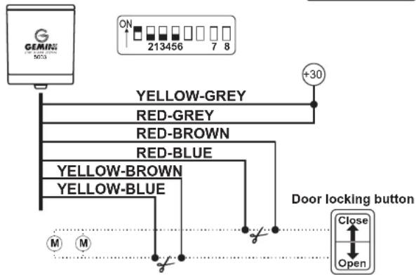
Ref.: Diagram No. 3
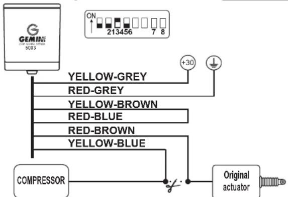
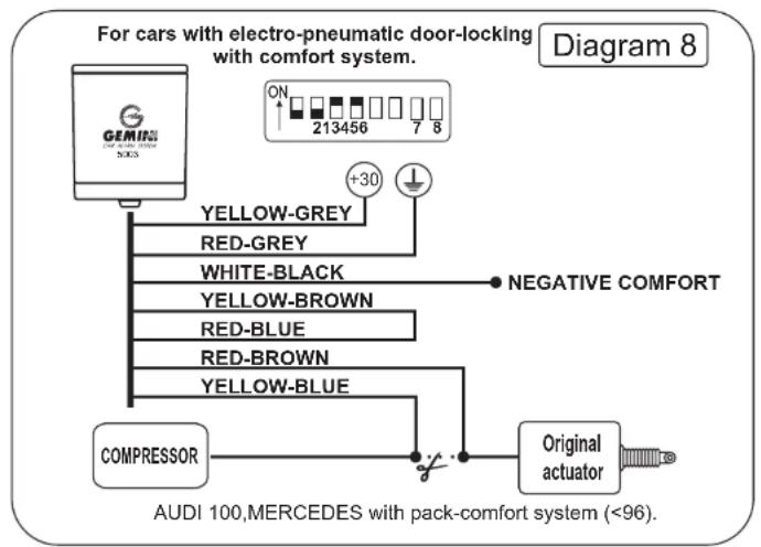
For cars already equipped with electro-pneumatic central locking with an actuator in the driver's door (i.e. Mercedes, Audi).
Ref.: Diagram No. 4
For cars already equipped with electrical central locking with an actuator in the driver's door and where the central locking is controlled only through an existing switch installed inside the passenger's compartment.
Ref.: Diagram No. 5
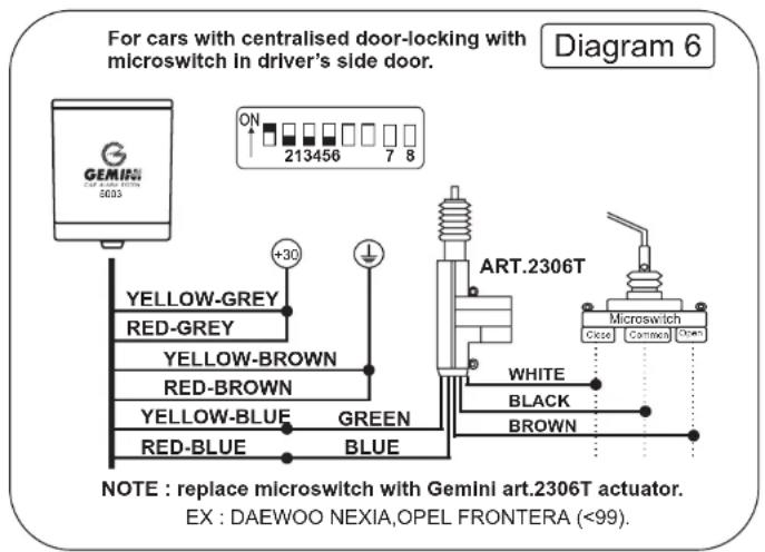
For cars already equipped with central locking without an actuator in the driver's door a Gemini 2305 must be used, (i.e. Nissan).
Ref.: Diagram No. 6
For cars already equipped with central locking with a micro switch and not an actuator in the driver's door, (i.e. Volkswagen, Saab) remove the existing micro switch and fit a Gemini 2306 in its place.
FOR CARS WITH TOTAL CLOSE FACILITY
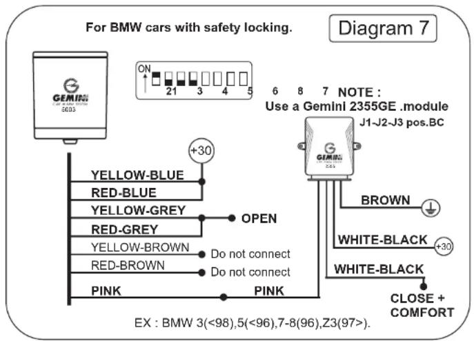
Ref.: Diagram N. 7
For BMW Series 5, 7 and 8 after 1988, where it is possible to close central locking electric windows and sunroof and dead locking off the driver's door key.
Ref.: Diagram No. 8
For Mercedes and Audi, where it is possible to close the windows and sunroof off the driver's door key.
Ref.: Diagram No. 9
For Vauxall (Cavalier, Carlton Calibra), Jaguar, Audi 100 with original alarm and Porsche 928 GT 1991 onwards where it is possible to close windows and sunroof off driver's door key (sunroof on Porsche 928 GT and Audi 100 with O.E. alarm is possible).
Ref.: Diagram No. 10
A. Specific for Mercedes SE, SEL and SEC (W140, C140 and R129 Series), Volvo 480 ES 1992.
B. Specific for Volkswagen all models except Polo, Passat electric sunroof.
For these connections an additional relay (Gemini 2352) must be used with a diode on pins 85 - positive 86 - earth.
ULTRASONIC ADJUSTMENT AND TEST PROCEDURE
a. Lower one of the front windows approximately 20 cm.
b. Adjust the sensitivity fully anti-clockwise.
c. Plug L.E.D. into the back of the unit.
d. Arm the alarm and push your arm through the window. The L.E.D. will give a one second flash when movement has been detected. If L.E.D. does not flash, turn the sensitivity clockwise, until L.E.D. does pick up movement.
e. Finally close all windows and gently go round the vehicle tapping the windscreen and window. If the alarm goes off you MUST reduce the sensitivity.
f. Reconnect L.E.D. into harness and fix fairlead onto siren with screws provided (fig. D).
g. Reconnect battery to terminal. Turn the external key switch to the "ON" position. The alarm acknowledges this operation as a disconnection and reconnection of the vehicles battery and for this reason will arm itself, after an exit delay time of 5 seconds. On the 5003 with the external key in "ON" position the battery back up circuits are operated, therefore, if the battery is to be disconnected for any reason (i.e. servicing) the external key switch must be turned anti-clockwise to the "OFF" position.
DO NOT OVERTIGHTEN HARNESS GAITER SECURING SCREWS.
PLEASE NOTE: STEAM CLEANING THIS ALARM SYSTEM WILL CAUSE IRREPARABLE DAMAGE AND VOID ANY WARRANTY CLAIM.
TABLE A
This table illustrates the respective arming period of each entry/sensor and the number of alarm cycles that each entry can generate.
| Exit Delay Time | Entry Sensors No. of Alarm | Cycles |
| 40 seconds | Door pin switches | 3 |
| 40 seconds | Bonnet/boot/tailgate switches | 3 |
| 5 seconds | Ignition live | Unlimited |
| 40 seconds | Volumetric, vibration and anti-lifting sensors | 6 |
| 40 seconds | Voltage drop sensor | Unlimited |
| 5 seconds | Battery back-up sensor | 5 |
| 5 seconds | Accessory Loop | 3 |
TECHNICAL DATA GEMINI 5002/3
| Power supply 12 VDC | |
| Current Draw | 12 mA |
| Working Temperature | -30^ + 85^ C |
| Engine Immobilisation Relay Contacts | 30 A |
| Visual Signalling Relay Contacts | 20 A |
| Audible Tone Relay Contacts | 2 A |
| Central Locking Relay Contacts | 10 A |
| Immunity | 50 V/m |
| Alarm Period | 25 < > 30 sec. |
| Sound Level at 1 metre | 122 dB |
| Minimum Power Absorption to Trigger | 5 W |
The manufacturer declines every responsibility for any possible defect or failure to the device and to the car's electric system due to a bad installation or to the overcome of the indicated technical features. The alarm has exclusively a dissuasive function against possible thefts.
flowchart
graph TD
    A["WIRING DIAGRAM 5003-5002"] --> B["6108GE (325MHz) 6108E (433MHz)"]
    B --> C["6008GE (325MHz) 6008E (433MHz)"]
    C --> D["TX"]
    C --> E["RX"]
    D --> F["See diagram of centralised locks"]
    E --> F
    F --> G["YELLOW-BLUE"]
    F --> H["RED-BLUE"]
    F --> I["YELLOW-GREY"]
    F --> J["RED-GREY"]
    F --> K["YELLOW-BROWN"]
    F --> L["RED-BROWN"]
    G --> M["Door pushbutton"]
    H --> N["Green-BROWN"]
    I --> O["Bonnet / Boot pushbuttons"]
    J --> P["GREEN"]
    K --> Q["Turn indicators"]
    L --> R["External Sensor inlet"]
    M --> S["Green-BLACK"]
    N --> T["ORANGE"]
    O --> U["ORANGE"]
    P --> V["ORANGE"]
    Q --> W["ORANGE"]
    R --> X["ORANGE"]
    S --> Y["ORANGE"]
    T --> Z["ORANGE"]
    U --> AA["ORANGE"]
    V --> AB["BROWN-BLACK"]
    W --> AC["BROWN"]
    X --> AD["BLENT"]
    Y --> AE["BLENT"]
    Z --> AF["AERIAL Do not tamper!"]
    AA --> AG["AUXiliary contact (NC)"]
    AB --> AH["ON 1 2 3 4 5 6 7 8"]
    AC --> AI["Red Black"]
    AD --> AJ["5A RED"]
    AE --> AK["10A WHITE-RED"]
    AF --> AL["+ Battery 12 VOLT"]
    AG --> AM["PINK Positive alarm ON"]
    AH --> AN["BROWN EARTH"]
    AI --> AO["WHITE-BLACK Negative Comfort"]
    AJ --> AP["BLENT Supplementary Siren"]
    AK --> AQ["BLENT Supplementary Siren"]
    AL --> AR["BLENT Supplementary Siren"]
    AM --> AS["BLENT Supplementary Siren"]
    AN --> AT["BLENT Supplementary Siren"]
    AO --> AU["BLENT Supplementary Siren"]
    AP --> AV["BLENT Supplementary Siren"]
    AQ --> AW["BLENT Supplementary Siren"]
    AR --> AX["BLENT Supplementary Siren"]
    AS --> AY["BLENT Supplementary Siren"]
    AT --> AZ["BLENT Supplementary Siren"]
    AU --> BA["BLENT Supplementary Siren"]
    AV --> BB["BLENT Supplementary Siren"]
    AW --> BC["BLENT Supplementary Siren"]
    AX --> BD["BLENT Supplementary Siren"]
    AY --> BE["BLENT Supplementary Siren"]
For cars with electrical centralised door-loocking with negative or positive control.
Diagram 2
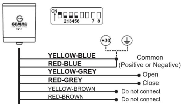
EX : ALFA, FIAT, FORD, LANCIA, SAAB, SUZUKI IGNIS (02), JIMMY (02)
For cars with electric centralised door-locking controlled only by door-locking button.
Diagram 4
flowchart
graph TD
    A["ON"] --> B["213456 7 8"]
    B --> C["+30"]
    D["YELLOW-GREY"] --> E["Red-GREY"]
    F["RED-BROWN"] --> G["Red-BLUE"]
    H["YELLOW-BROWN"] --> I["YELLOW-BLUE"]
    J["Door locking button"] --> K["Close"]
    L["Open"] --> M["M M"]
EX : RENAULT TWINGO (<2000)
For cars with electro-pneumatic centralised door-locking
Diagram 3
flowchart
graph TD
    A["GENMING 5003"] --> B["YELLOW-GREY"]
    A --> C["RED-GREY"]
    A --> D["YELLOW-BROWN"]
    A --> E["RED-BLUE"]
    A --> F["RED-BROWN"]
    A --> G["YELLOW-BLUE"]
    B --> H["+30"]
    C --> H
    D --> H
    E --> H
    F --> H
    G --> H
    H --> I["Original actuator"]
    J["COMPRESSOR"] --> I
EX : AUDI 80, MERCEDES 190.
For car with centralised door-locking without actuator in driver's side door.
Diagram 5
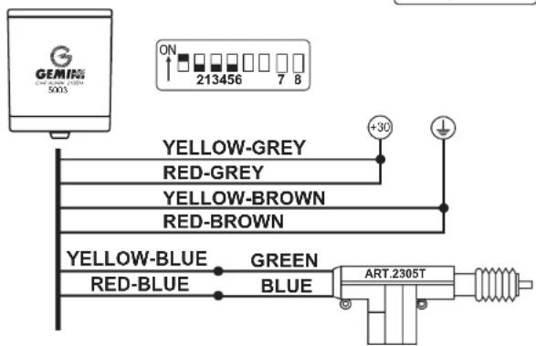
EX : HONDA CIVIC 5p(96), HYUNDAI ACCENT (96), GALLOPER (98)
flowchart
graph TD
    A["For cars with electro-pneumatic door-locking with comfort system."] --> B["COMPRESSOR"]
    B --> C["Original actuator"]
    C --> D["RED-BROWN"]
    D --> E["RED-BLUE"]
    E --> F["WHITE-BLACK"]
    F --> G["RED-GREY"]
    G --> H["YELLOW-GREY"]
    H --> I["+30"]
    I --> J["ON 213456 7 8"]
    J --> K["Negative COMFORT"]
    K --> L["Original actuator"]
    style A fill:#f9f,stroke:#333
    style B fill:#ccf,stroke:#333
    style C fill:#cfc,stroke:#333
    style D fill:#fcc,stroke:#333
    style E fill:#cff,stroke:#333
    style F fill:#ffc,stroke:#333
    style G fill:#cfc,stroke:#333
    style H fill:#fcc,stroke:#333
    style I fill:#ffc,stroke:#333
    style J fill:#cfc,stroke:#333
    style K fill:#fcc,stroke:#333
    style L fill:#cfc,stroke:#333
flowchart
graph TD
    A["For BMW cars with safety locking. Diagram 7"] --> B["Yellow-BLUE"]
    A --> C["RED-BLUE"]
    A --> D["YELLOW-GREY"]
    A --> E["RED-GREY"]
    A --> F["YELLOW-BROWN"]
    A --> G["RED-BROWN"]
    A --> H["PINK"]
    A --> I["PINK"]
    J["Use a Gemini 2355GE .module J1-J2-J3 pos.BC"] --> K["BROWN"]
    J --> L["WHITE-BLACK"]
    J --> M["WHITE-BLACK"]
    J --> N["CLOSE + COMFORT"]
    O["EX : BMW 3(<98),5(<96),7-8(96),Z3(97>)."] --> P["OPEN"]
    Q["+30"] --> R["OPEN"]
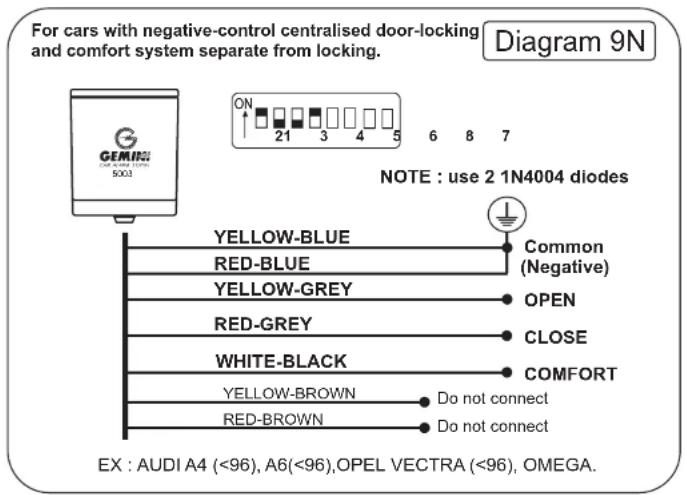
For cars with centralised door-locking and comfort system controlled by locking function.
Diagram 10
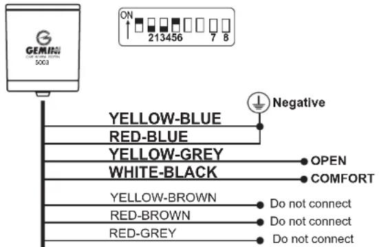
EX : AUDI A3, A4 (97>), A6 (97>), BMW 3 (98), 5 (96>), OPEL, VW
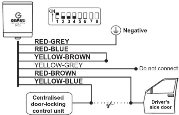
For cars with electrical centralised door-locking with negative control only on closing.
Diagram 23
flowchart
graph TD
    A["GEMIN 5003"] --> B["RED-GREY"]
    A --> C["RED-BLUE"]
    A --> D["YELLOW-BROWN"]
    A --> E["YELLOW-GREY"]
    A --> F["RED-BROWN"]
    A --> G["YELLOW-BLUE"]
    H["Driver's side door"] --> I["Centralised door-locking control unit"]
    I --> J["Do not connect"]
    J --> K["Negative"]
    K --> L["ON 1 2 3 4 5 6 7 8"]
EX : CITROEN XSARA, FIAT ULISSE (98), LANCIA Z (98), PEUGEOT 306
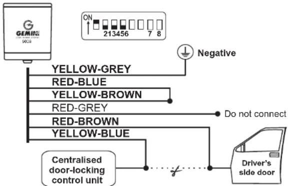
For cars with electrical centralised door-locking with negative control only on opening.
Diagram 22
flowchart
graph TD
    A["503GEMIR Device"] --> B["Yellow-GREY"]
    A --> C["RED-BLUE"]
    A --> D["YELLOW-BROWN"]
    A --> E["RED-GREY"]
    A --> F["RED-BROWN"]
    A --> G["YELLOW-BLUE"]
    B --> H["Do not connect"]
    C --> H
    D --> H
    E --> H
    F --> H
    G --> H
    H --> I["Centralised door-locking control unit"]
    I --> J["Driver's side door"]
    K["ON 213456 7 8"] --> L["Negative"]
EX : NISSAN MICRA(>97), SUZUKI IGNIS (00), JIMMY (99)
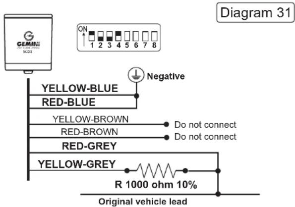
EX : SKODA FABIA, VW POLO (02>)
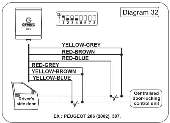
flowchart
graph TD
    A["Driver's side door"] --> B["Yellow-Grey"]
    A --> C["Red-Brown"]
    A --> D["Red-BLUE"]
    A --> E["Yellow-Brown"]
    A --> F["Yellow-BLUE"]
    B --> G["Centralised door-locking control unit"]
    C --> G
    D --> G
    E --> G
    F --> G
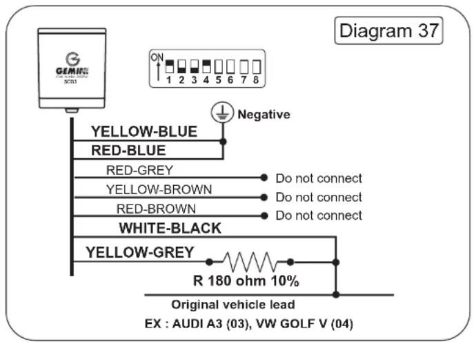
- 5002/3 INSTALLATION INSTRUCTIONS
- The alarms offer the following protections:
- The alarms also have the following abilities:
- PRE-INSTALLATION CHECKS
- Ref.: Diagram No. 2
- Ref.: Diagram No. 3
- Ref.: Diagram No. 4
- Ref.: Diagram No. 5
- Ref.: Diagram No. 6
- FOR CARS WITH TOTAL CLOSE FACILITY
- Ref.: Diagram N. 7
- Ref.: Diagram No. 8
- Ref.: Diagram No. 9
- Ref.: Diagram No. 10
- ULTRASONIC ADJUSTMENT AND TEST PROCEDURE
Brand : GEMINI
Model : 5002
Category : Car alarm