MSD-701 - Monitor AMX - Free user manual and instructions
Find the device manual for free MSD-701 AMX in PDF.


| Product Type | Monitor |
| Brand | AMX |
| Model | MSD-701 |
| Display Size | 17 inches |
| Resolution | 1920 x 1080 (Full HD) |
| Panel Type | LED-backlit LCD |
| Aspect Ratio | 16:9 |
| Brightness | 250 cd/m² |
| Contrast Ratio | 1000:1 |
| Response Time | 5 ms |
| Viewing Angles | 178° horizontal / 178° vertical |
| Connectivity | VGA, HDMI, DVI-D, USB |
| Power Consumption | 30 W (typical) |
| Power Supply | AC 100-240V, 50/60Hz |
| Dimensions (W x H x D) | 16.1 x 12.6 x 2.0 inches (409 x 320 x 51 mm) |
| Weight | 8.8 lbs (4.0 kg) |
| VESA Mount | 100 x 100 mm |
| Built-in Speakers | Yes, 2 x 2W |
| Cleaning Instructions | Wipe with a soft, dry cloth. Do not use liquid cleaners. |
| Safety Features | Overvoltage protection, Kensington lock slot |
| Spare Parts | Power adapter, VGA cable, user manual |
Frequently Asked Questions - MSD-701 AMX
User questions about MSD-701 AMX
0 question about this device. Answer the ones you know or ask your own.
Ask a new question about this device
Download the instructions for your Monitor in PDF format for free! Find your manual MSD-701 - AMX and take your electronic device back in hand. On this page are published all the documents necessary for the use of your device. MSD-701 by AMX.
USER MANUAL MSD-701 AMX
The Modero S Series ^® is a beautiful touch panel family sophisticated enough for room control yet priced right for the most cost sensitive installations including small huddle spaces and dedicated room scheduling. The MSD-701-L 7" Wall/Flush Mount Touch Panel (FG2265-02) features brilliant 24-bit color depth, PoE connectivity, and streaming video.
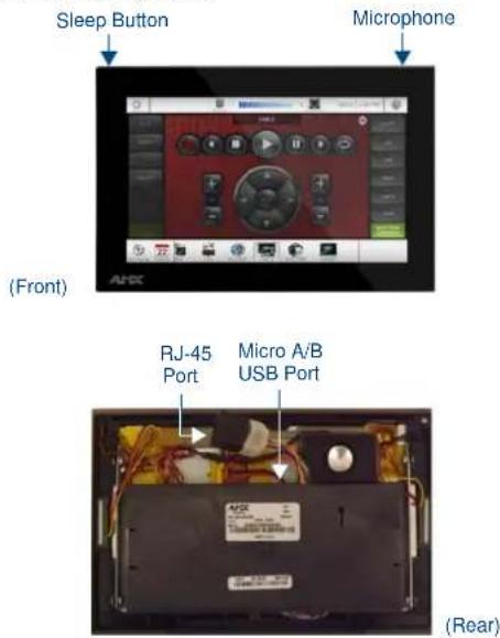
FIG. 1 MSD-701-L
Product Specifications
| MSD-701-L Specifications | |
| Power: PoE (Power over | Ethernet), 802.3af, class 0 |
| Power Consumption: • Maximum: 11W• Standby: 4.5W• Shutdown: 1W• Startup Inrush Current: Not Applicable due to PoE standard | |
| Operating Environment: | • Operating Temperature: 32°F to 104°F (0°C to 40°C)• Storage Temperature: 4°F to 140°F (-20°C to 60°C)• Humidity Operating: 20% to 85% RH• Humidity Storage: 5% to 85% RH• Power ("Heat") Dissipation: 37.5 BTU/hr, Standby: 15.4 BTU/hr |
| Dimensions (HWD): | With Back Box: 4.88" x 7.40" x 2.30"(123.95 mm x 187.96 mm x 58.42 mm) |
| Weight: | • Without Back Box: 0.80 lbs (0.22 Kg)• With Back Box: 1.05 lbs (0.36 Kg) |
| Certifications: • UL | • FCC Part 15 Class B• C-Tick CISPR 22 Class B• CE EN 55022 Class B and EN 55024• CE EN 60950-1• IC CISPR 22 Class B• VCCI CISPR 22 Class B• RoHS/WEEE compliant |
| Included Accessories: | • MSD-701-L Wall Mounting Template (68-2265-02) |
Note: Optimal performance requires use of one of the following AMX PoE power supplies (not included):
• PS-POE-AF-TC, PoE Injector, 802.3AF Compliant (FG423-83)
• NXA-ENET8-2POE, Gigabit PoE Ethernet Switch (FG2178-63)
Note: AMX does not support the use of non-AMX power supplies.
Note: For more information on installation and configuration, as well as complete specifications on this device, please refer to the MSD/T-701
Operation/Reference Guide, available at www.amx.com.
Panel Connectors and Wiring
FIG. 1 shows the connectors located on the back of the MSD-701-L.
Power for the MSD-701-L via Power Over Ethernet
Power for the MSD-701-L is supplied via Power Over Ethernet (PoE), utilizing an AMX-certified PoE injector such as the PS-POE-AF-TC PoE Injector (FG423-83) or other approved AMX PoE power source. The incoming Ethernet cable should be connected to the RJ-45 port on the MSD-701-L.
Note: The Micro A/B USB port is used only for firmware uploads, as it is inaccessible when the device is installed within its back box.
Installing the MSD-701-L
The MSD-701-L can be installed either directly into a solid surface environment, using either solid surface screws or the included locking tabs for different mounting options. For more information, please refer to the MSD/T-701 Operation/Reference Guide, available at www.amx.com.
Installing the MSD-701-L into a wall
The MSD-701-L is contained within a clear outer housing known as the back box. The back box (FIG. 2) is designed to attach the panel to most standard wall and solid surface materials. This back box has two locking tabs (one on the top and one at the bottom) to help lock the back box to the wall. These locking tabs are only extended AFTER the back box is inserted into the wall. Using the locking tabs is highly recommended for standard mounting surfaces such as walls. For thin walls and solid surfaces, use #4 mounting screws (not included).
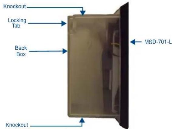
FIG. 2 MSD-701-L Back Box (Side View)
WARNING: When installing the back box, make sure that the assembly is in the correct position and in the correct place. Once the locking tabs are extended and locked into place, removing the back box may be difficult without having access to the back of the wall or causing damage to the wall.
Note: In order to guarantee a stable installation of the MSD-701-L, the thickness of the wall material must be a minimum of .50 inches (1.27cm) and a maximum of .875 inches (2.22cm). The surface should also be smooth and flat.
WARNING: The maximum recommended torque to screw in the locking tabs on the plastic back box is 5 IN-LB [56 N-CM]. Applying excessive torque while tightening the tab screws, such as with powered screwdrivers, can strip out the locking tabs or damage the plastic back box.
- After ensuring proper placement, cut out the mounting surface. Use the included mounting template (68-2265-02) or refer to the dimensions in the MSD/T-701 Operation/Reference Guide, available from www.amx.com, for more information.
CAUTION: Making sure the actual cutout opening is slightly smaller than the provided dimensions is highly recommended. This action provides the installer with a margin for error if the opening needs to be expanded. Too little wall material removed is always better than too much.
-
Remove either the top or the bottom knockout from the back box, depending upon the required installation. Thread the incoming wiring through the hole in the rear of the back box.
-
Thread the incoming Ethernet wiring from their terminal locations through the surface opening and through the access slot.
-
Push the back box flat into the mounting surface and secure with either the locking tabs or #4 mounting screws (not included). In order to prevent damage to the touch panel, make sure that any screws used are flush with the back box, and the back box goes freely into the opening.
- Insert each connector into its corresponding location along the back of the MSD-701-L.
- Test the incoming wiring by attaching the panel connections to their terminal locations and applying power. Verify that the panel is receiving power and functioning properly to prevent repetition of the installation.
Note: Do not disconnect the connectors from the touch panel. The unit must be installed with the attached connectors before being inserted into the drywall.
- Latch the panel onto the top hooks on the back box and rotate it down. Press gently but firmly and evenly on the surface of the glass until the top panel snap "clicks" to lock it down.
WARNING: if you see a gap between the panel and the back box, or feel any binding while locking down the panel, stop immediately and verify that no cables or other items are in the way. Do not force the panel into position, as this can cause damage to the touch screen or the panel electronics.
8. Reconnect the terminal Ethernet to its respective locations on either the Ethernet port or NetLinx Master.
Uninstalling the MSD-701-L
In order to access the back of the MSD-701-L, such as to install a USB connection for firmware upgrades, the device may need to be uninstalled from the back box. To uninstall the MSD-701-L:
- From the bottom, pull gently outward from the back box. Gently rock the panel back and forth to free the bottom from the back box.
- Rotate it up to release the top latch hooks, and carefully pull the device free from the back box. Take care not to damage or pull the connections on the back of the device.
Configuring the MSD-701-L
The MSD-701-L is equipped with Settings Pages that allow you to set and configure various features on the panel. For more information on connecting and configuring the MSD-701-L to a network, please refer to the Modero S Series Programming Guide, available at www.amx.com.
Accessing the Settings Pages
To access the Settings Pages on the MSD-701-L, press and hold the Sleep Button (FIG. 1) on the top of the panel for 3 seconds. The user will be prompted to release the button to enter the Settings page (FIG. 3).
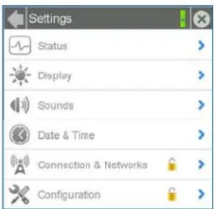
FIG. 3 Settings page
Accessing the Configuration Page
- From the Settings Page, select Configuration. If the Configuration page is password protected, this opens a password keypad.
- Enter the panel password into the keypad (the default is 1988) and select OK to access the page.
Setting the Panel's Device Number and Device Name
In the Configuration page:
- Press Panel to open the Panel Configuration page.
- Ensure that the Synchronize Device Names button is not selected, and click it to deselect it if it is.
- Press Device Number to open the Device Number keypad.
- Enter a unique Device Number assignment for the panel and press OK.
- Press the Device Name field to open the Device Name keypad.
- Enter a unique Device Name assignment for the panel and press OK.
Accessing the Connection & Networks Page
- From the Settings Page, select Connection & Networks. If the page is password protected, this opens a password keypad.
- Enter the panel password into the keypad (the default is 1988) and select OK to access the page.
Connecting to a Master
The panel requires that you establish the type of connection you want to make between it and your Master.
In the Connection & Networks page:
- Select Master Connection to open the Master Connection page (FIG. 4).
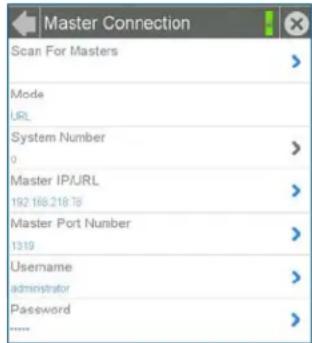
FIG. 4 Master Connection page
- Press Mode to toggle through the available connection modes:
| Connection Modes | ||
| Mode | Description Procedures | |
| Auto Th | The device connects to the first master that responds.This setting requires that you set the System Number. | Setting the System Number:1. Select Master System Number to open the keypad.2. Set your Master System Number and select OK. |
| URL Th | The device connects to the specific IP of a master via a TCP connection.This setting requires that you set the Master's IP. | Setting the Master IP:1. Select the Master IP number to the keyboard.2. Set your Master IP and select OK. |
| Listen Th | The device "listens" for the Master to initiate contact.This setting requires you provide the master with the device's IP. | Confirm device IP is on the Master URL list. You can set the Host Name on the device and use it to locate the device on the master. Host Name is particularly useful in the DHCP scenario where the IP address can change. |
- If you have enabled password security on your Master, you need to set the username and password within the device.
a. Select Username to open the Master User keyboard.
b. Set your Username and select OK.
c. Select the Password to open the Master Password keyboard.
d. Set your Master Password and select OK.
e. Press the Back button twice to return to the Settings page.
Configuring the Panel to a Network
The first step is to configure the panel's communication parameters. This only configures the panel to communicate with a network, and it is still necessary to tell the panel with which Master it should be communicating.
Network Communication With a DHCP Address
In the Connection & Networks page:
- Select Network Connection to open the Network Connection page.
- Toggle the DHCP/Static field until the choice cycles to DHCP. This action causes all fields on the page (other than Host Name) to be greyed-out.
- Select Host Name to open the Host Name keyboard. Enter the new host name and click OK.
- Panel Connectors and Wiring
- Power for the MSD-701-L via Power Over Ethernet
- Installing the MSD-701-L
- Uninstalling the MSD-701-L
- Configuring the MSD-701-L
- Accessing the Settings Pages
- Accessing the Configuration Page
- Setting the Panel's Device Number and Device Name
- Accessing the Connection & Networks Page
- Connecting to a Master
- Configuring the Panel to a Network
- Network Communication With a DHCP Address
Brand : AMX
Model : MSD-701
Category : Monitor