CAMERA-CTL-2 - Uncategorized DVDO - Free user manual and instructions
Find the device manual for free CAMERA-CTL-2 DVDO in PDF.


| Product Type | Camera Controller |
| Brand | DVDO |
| Model | CAMERA-CTL-2 |
| Dimensions (W x H x D) | 120 mm x 80 mm x 30 mm |
| Weight | 200 g |
| Power Supply | 5V DC via USB-C |
| Power Consumption | 2.5 W |
| Connection Interface | Bluetooth 5.0, USB-C |
| Range | Up to 30 m (line of sight) |
| Compatible Devices | DVDO cameras and selected third-party cameras |
| Primary Functions | Pan, tilt, zoom control; preset recall; record start/stop |
| Joystick Type | 3-axis proportional joystick |
| Display | 2.4-inch color LCD |
| Button Count | 12 programmable buttons |
| Battery Type | Built-in rechargeable Li-ion |
| Battery Capacity | 3000 mAh |
| Operating Time | Approximately 8 hours |
| Charging Time | 2 hours |
| Operating Temperature | 0°C to 40°C |
| Maintenance | Clean with a soft, dry cloth; avoid liquids |
| Safety Precautions | Do not expose to moisture or extreme temperatures |
| Spare Parts Availability | Battery, USB cable, joystick cap available from DVDO |
| Repairability | Modular design; user replaceable battery and joystick |
| Additional Features | Backlit buttons, vibration feedback, tripod mount |
Frequently Asked Questions - CAMERA-CTL-2 DVDO
User questions about CAMERA-CTL-2 DVDO
0 question about this device. Answer the ones you know or ask your own.
Ask a new question about this device
Download the instructions for your Uncategorized in PDF format for free! Find your manual CAMERA-CTL-2 - DVDO and take your electronic device back in hand. On this page are published all the documents necessary for the use of your device. CAMERA-CTL-2 by DVDO.
USER MANUAL CAMERA-CTL-2 DVDO
natural_image
3D rendering of a black industrial control panel with control buttons and a cylindrical actuator (no visible text or symbols)DVDO-Camera-Ctl-2
IP PTZ Camera Controller with Joystick
User Manual
Version v1.0
Thank you for purchasing DVDO-Camera-Ctl-2
For optimum performance and safety, please read these instructions carefully before connecting, operating or adjusting this product. Please keep this manual for future reference. reference.
Surge protection device recommended
This product contains sensitive electrical components that may be damaged by electrical spikes, surges, electric shock, lighting strikes, etc. Use of surge protection systems is highly recommended in order to protect and extend the life of your equipment.
1. Product Overview
1.1 Description
DVDO-Camera-Ctl-2 is a PTZ camera controller with a joystick, an LCD screen as well as multiple knobs and backlit buttons. It can control up to 255 PTZ cameras over IP and/or serial (hybrid). Controls include Pan, Tilt, Zoom, PTZ speed, Focus, Iris, White Balance and R/B color correction. The web-based GUI allows easy set up and configuration of the cameras. DVDO-Camera-Ctl-2 can be powered either by its external power supply or over ethernet (PoE).
1.2 Features
- Controls up to 255 PTZ cameras over IP and/or serial (RS232/RS422/RS485 within the same network
- Supports NDI, ONVIF, VISCA & Pelco protocols and auto-discovery
- 4D joystick (up/down, left/right, zoom in/out, confirm) with variable speed for Pan, Tilt and Zoom controls
- Additional circular knob for zoom adjustment
- 7 buttons for direct camera selections
- Other controls include PTZ speed, Focus, Iris, White Balance and R/B color correction
- Web-based GUI for easy setup and configuration
- Tally control function
- Two power options: PoE or external 12V power supply
2. Product Interface Description
2.1 Interface Description
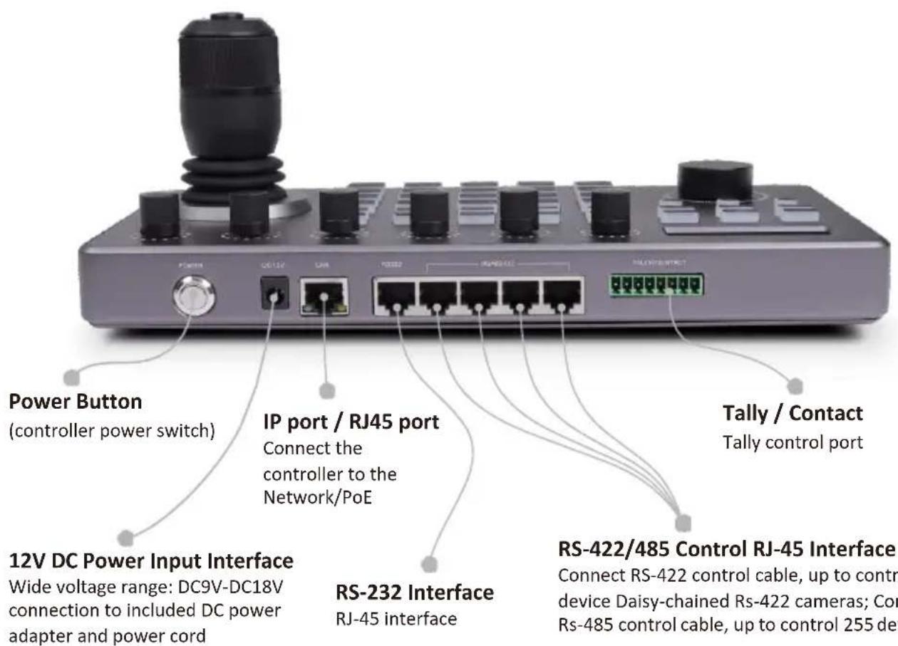
- Button Function Description
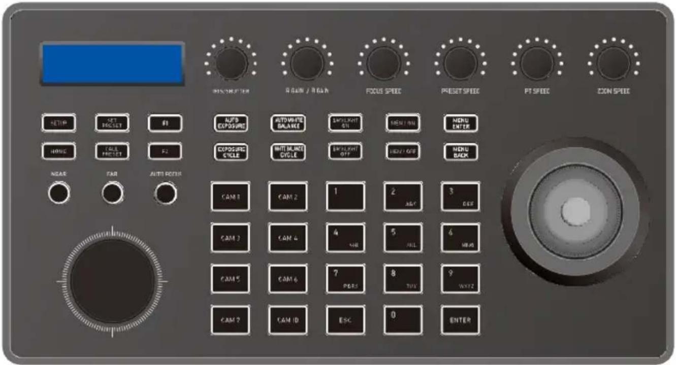
3.1 Functional Button Desciption
Camera Function Section
| HOME: | Home | MENU ON: | Menu On |
| AUTO EXPOSURE: | Auto Exposure | MENU OFF: | Menu Off |
| EXPOSURE CYCLE: | Exposure adjust Auto | MENU ENTER: | Menu Confirm |
| AUTO WHITE BALANCE: | white balance White | MENU BACK: | Menu Back |
| WHITE BALANCE CYCLE: | balance adjust | NEAR: | Focus + |
| BACKLIGHT ON: | Backlight on | FAR: | Focus - |
| BACKLIGHT OFF: | Backlight off | AUTOFOCUS: | Auto focus |
Knob Function Section Controller Functional Button
| IRIS/SHUTTER: | Aperture/Shutter adjust | SETUP: | Set controller native settings |
| R GAIN: | Red gain + - | CALL PRESET: | Call preset |
| B GAIN: | Blue gain + - | CAM ID: | Camera address |
| FOCUSSPEED: | Focus speed adjust | ESC: | Exit |
| PRESETSPEED: | Preset speed adjust PT | ENTER: | Confirm |
| ZOOM SPEED: | speed adjust Zoom speed | NUMBER0-9 | Number Key, IP, Preset, etc |
| JOG KNOB: | adjust Zoom + - |
Shortcut Function Section
CAM1-7: 1-7 Cameras Switch Button
F1-F2: Custom hexadecimal command buttons
| Keyboard Setup | Description | |
| 1. Add IP Device | Can add: Onvif, Visca over IP (TCP / UDP) | |
| 2. Add Analog Device | Can add: Visca, Pelco (D / P) | |
| 3. Switch Controller Mode | Controller enter into Network mode / Analog mode | |
| 4. Device List | Display the added camera information | |
| 5. Type: Static / Dynamic | Network Type | Switch the joystick left and right, [Enter] confirm |
| DHCP | Dynamic allocation according to the switch | |
| Static | Need to set in IP, gateway, subnet mask | |
| 6. System Language: EN/CH | Switch the joystick left and right, [Enter] button to confirm | |
| 7. Button Touch-tone | Switch the joystick left and right, [Enter] button to confirm | |
| 8. Reset | Press [Enter] twice to enter recovery, [Esc] to cancel | |
| 9. System Infomation | Display version number, local network parameters | |
| 10. VISCA Return code Enable / Disable | Switch the joystick left and right, [Enter] button to confirm | |
3.2 Description of Rotary Joystick
| Operate | Output | Operate | Output | Operate | Output |
 | Up | 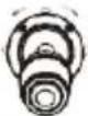 | Down |  | Left |
| Operate | Output | Operate | Output | Operate | Output |
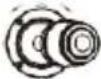 | Right | 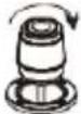 | Zoom + | 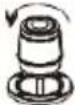 | Zoom - |
Joystick [Up, Down, Left, Right]: Control the PTZ to turn up, down, left and tight.
Joystick [rotate left and right]: Rotate the joystick to zoom function, rotate right to zoom +, zoom
4. Controller Connection & Control Device
255 Cameras respectively adopt RS485 Pelco protocol
7 Cameras respectively provided by Visca via RS422 group
255 Cameras adopt Visca Over IP protocol respectively
A total of 255 cameras are controlled by cross-protocol mixing
> Add Network Camera
(1) Press the enter button to enter the cameras ID
(2) Set to select IP Visca (Onvif, Sony Visca) protocol
(3) Press [Enter] button to save (After input enter)
(4) Enter the IP address of the camera
(5) Enter port number
(6) Enter camera username, password
(7) IP Visca (Sony Visca) protocol does not need to input camera username, password
Port: IP control port
Sony Visca defaults to 52381
IP Visca defaults to 1259
ONVIF default to 2000 or 80
If you have multiple Visca Over IP
cameras different manufactures,
you may have to set different
> Network mode connection diagram
The controller and PTZ camera are connected in the same LAN, and the IP addresses are in the same network segment, such as: 192.168.1.123 and 192.168.1.111.
Belong to the same network segment; If not in the same LAN, you need to modify the IP address of the controller or camera at first, the default IP acquisition method of the controller is get it dynamically.
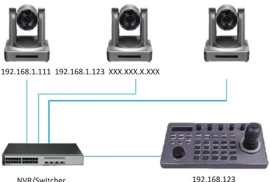
flowchart
graph TD
    A["192.168.1.111"] --> D["NVR/Switcher"]
    B["192.168.1.123"] --> D
    C["XXX.XXX.X.XXX"] --> D
    D --> E["192.168.123"]
(Applicable protocol: ONVIF/IPVISCA/NDI)
> Add Analog Camera
(1) Press the confirm button to enter the camera ID, set to select the Visca (Pelco D/P) protocol, press the [Enter] button to save
(2) Enter the camera address code, press [Enter] button to save
(3) Input camera baud rate, press [Enter] button to save
(4) Input serial port ID, press [Enter] button to save
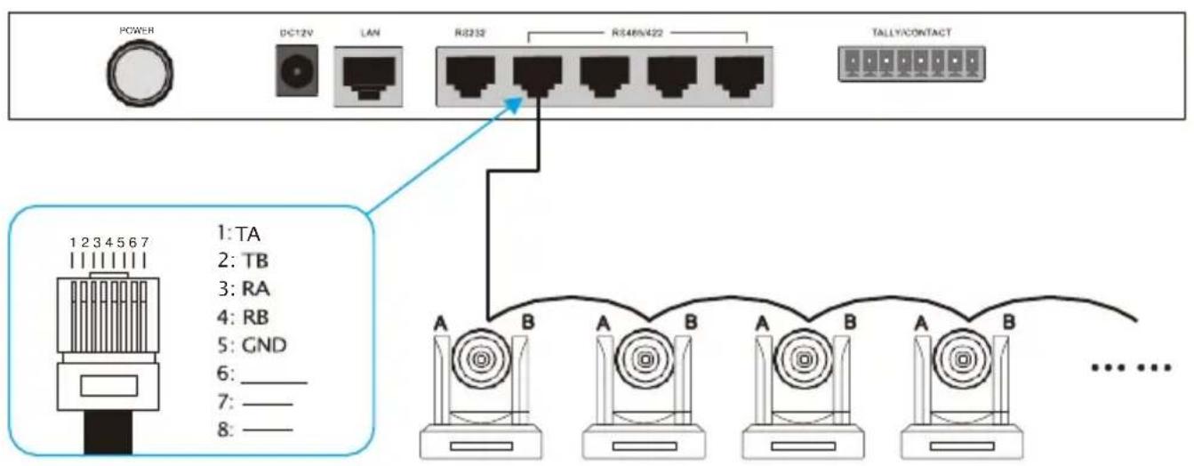
>Analog Mode Connection Diagram
(1) Analog Mode RS232
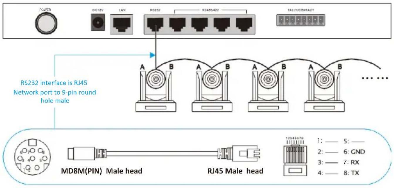
(2) Analog Mode RS485/RS422
5. Network Configuration
5.1 First connection and login
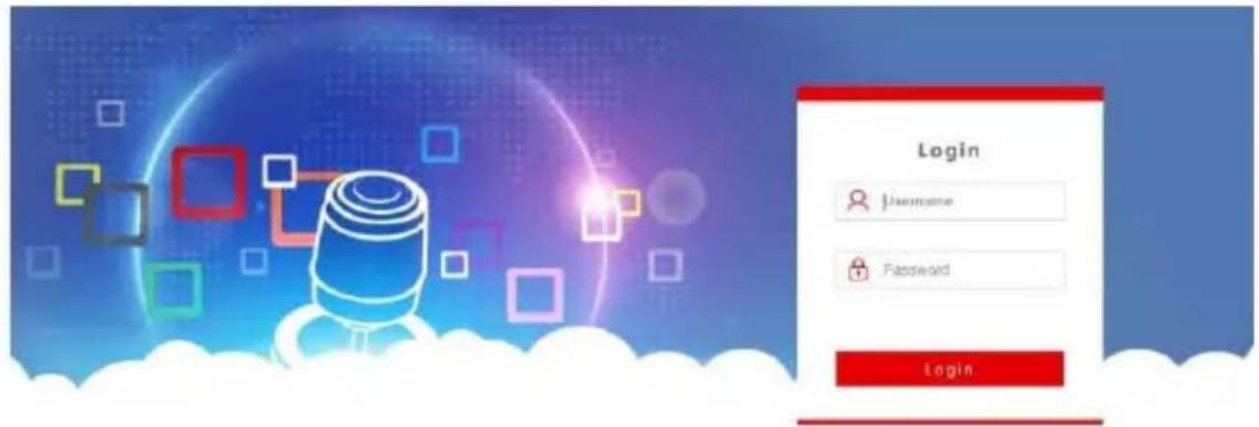
The controller and PTZ camera are connected in the same LAN, and the IP addresses are in the same network segment, such as: 192.168.1.123 and 192.168.1.111. Belong to the same network segment; If not in the same LAN, you need to modify the IP address of the controller or camera at first, the default IP acquisition method of the controller is get it dynamically.
(2) After entering the device web UI, the page is displayed as shown below.
| Device Management Settings | ||||||||
| Search Device Add Manufy | ||||||||
| Channel | IP | Port | Protocol(network) | Baudrate | Address | Protocol(analog) | Operate | |
| 1 | 192.168.1.102 | 1259 | VECA(UDP) | 5600 | 1 | PELCO-D | ✓ | |
| 2 | 192.198.1.102 | 00 | CNVIF | 5600 | 2 | PELCO-D | ✓ | |
| 3 | 192.198.5.170 | RR | CNVIF | 5600 | 3 | PELCO-D | ✓ | |
| 4 | 192.198.5.170 | 00 | CNVIF | 5600 | 4 | PELCO-D | ✓ | |
| 5 | 192.198.5.170 | 00 | CNVIF | 5600 | 5 | PELCO-D | ✓ | |
(3) After entering the homepage of the device, you can view the details of the device parameters and change them.
(4) Click the [ / ] button to add and modify device parameters in the LAN, the page is displayed as follows.
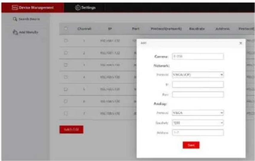
(Enter device number, corresponding IP address, port number and username click save.)
Notice:
When entering the controller web and add device successfully is synchronized with controller, in the web page adds the device successfully then click the controller corresponding to the number to control the dome camera.
5.2 Web UI Network Setting
The LAN settings can modify the IP acquisition method and port parameters of the device, as shown in the picture below:
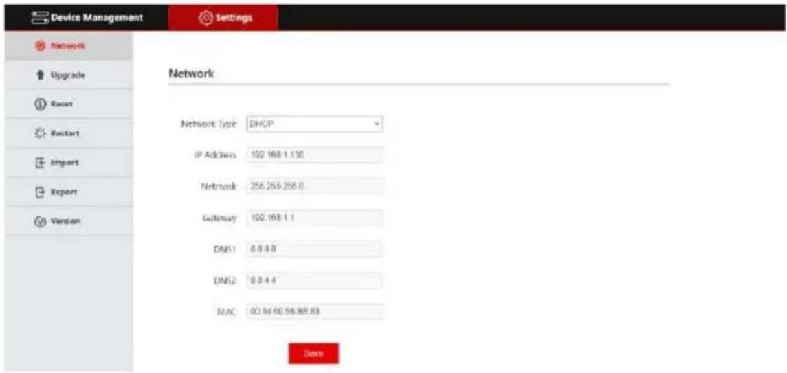
Static address (Static): When the user needs to set network segment by himself, change the network type to a static address, and fill in the network segment information to be modified.
Dynamic address (DHCP) (default acquisition method): The controller will automatically request an IP address from the router. After the request is successful, it will be displayed on the display screen of the controller. The displayed format is "Local IP: XXX,XXX,XXX,XXX".
5.3 System Upgrade
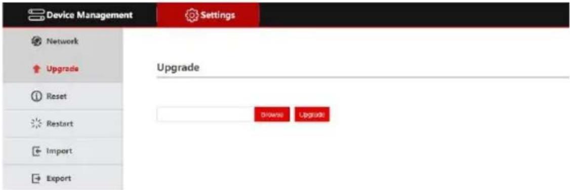
The upgrade function is used as a maintenance and update controller function. After entering the upgrade page, select the correct upgrade file and click [Start]. Note: Do not perform any operations on the device the upgrade process, and do not cut off the power or network!
5.4 System Reset
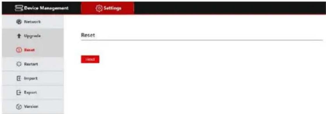
When clicking Device Reset, the controller will delete the configuration information and clear the added devices.
5.5 Restart
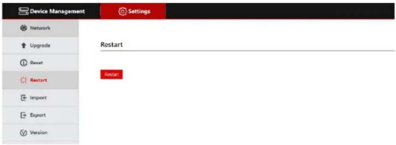
When the device has been running for a long time and needs to be restarted for maintenance, click Restart to achieve the purpose of restarting maintenance.
5.6 Import Configuration
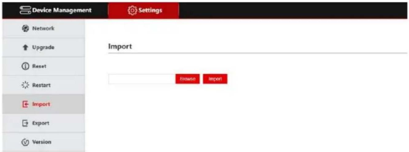
Import the device information of the previous controller (for example, when adding multiple devices to the previous controller, export the file type, and use it as an import to another device when adding a new controller).
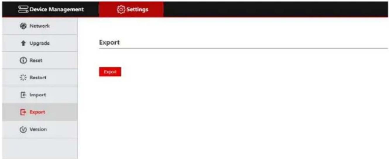
5.7 Export information
Export information about adding multiple devices to the current controller, which can be exported to other controller devices for use.
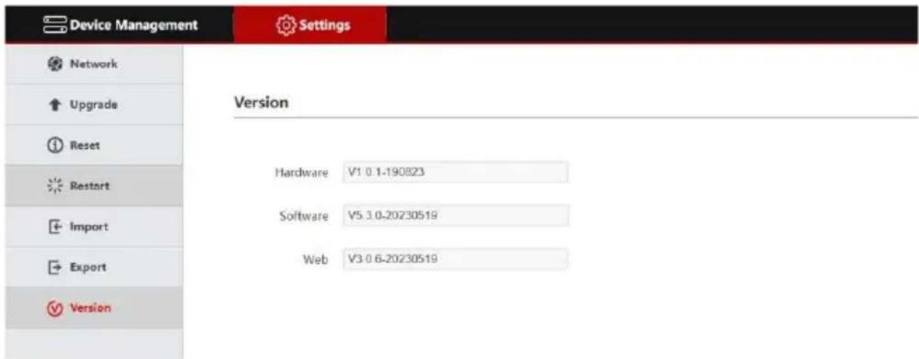
5.8 Version Information
Display the hardware and software information of the current controller.
6. FAQs
- When the screen displays "Connection Failed", please check whether the device corresponding to this IP is connected normally in the LAN.
- When the screen displays "Username password error", please check whether the username and password of the added device are correct.
- When adding another brand of equipment using the ONVIF protocol fails, check whether the camera has enabled the ONVIF protocol of the device.
NOTE: 1. Adding devices is manual.
- Enter the correct port number and device connection protocol in Add Device.
DVDO
Follow us


- DVDO-Camera-Ctl-2
- User Manual
- Thank you for purchasing DVDO-Camera-Ctl-2
- Surge protection device recommended
- Product Overview
- Description
- Features
- Product Interface Description
- Functional Button Desciption
- Description of Rotary Joystick
- Controller Connection & Control Device
- > Add Network Camera
- > Network mode connection diagram
- > Add Analog Camera
- >Analog Mode Connection Diagram
- Network Configuration
- First connection and login
- Notice:
- Web UI Network Setting
- System Upgrade
- System Reset
- Restart
- Import Configuration
- Export information
- Version Information
- FAQs
- DVDO
Brand : DVDO
Model : CAMERA-CTL-2
Category : Uncategorized